
Instruction manual
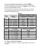
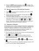
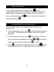
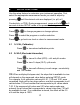
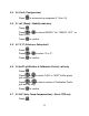
Table Of Contents
- 1. INTRODUCTION
- 2. GETTING STARTED
- 3. CONDUCTIVITY ELECTRODE
- 4. PH AND MV CALIBRATION
- 5. CONDUCTIVITY AND TDS CALIBRATION
- 6. CONDUCTIVITY AND TDS MEASUREMENT
- 7. HOLD FUNCTION
- 8. STORING AND RECALLING DATA
- 9. SETUP FUNCTIONS
- 9.1 1.0 CAL (Calibration)
- 9.2 2.0 ELE (Electrode Information)
- 9.3 3.0 ConF (Configuration)
- 9.4 3.1 rdY (Ready / Stability Indicator)
- 9.5 3.2 ºC ºF (Celsius or Fahrenheit)
- 9.6 3.3 buFF (pH Buffers & Calibration Points)—pH only
- 9.7 3.3 AtC (Auto Temp Compensation)—Con & TDS only
- 9.8 3.4 tdS (TDS factor)—Con & TDS only
- 9.9 3.5 t.CO (Temperature Coefficient)—Con & TDS only
- 9.10 3.6 t.nr (Normalization Temperature in ºC)—Con & TDS only
- 9.11 3.7 ACAL (Auto Conductivity Calibration)—Con & TDS only
- 9.12 3.8 SPC (Single Point Calibration)—Con & TDS only
- 9.13 3.8 CELL (Nominal Cell Constant)—Con & TDS only
- 9.14 4.0 rSt (Reset)
- 9.15 5.0 CLr (Clear Memory)
- 10. CALCULATING TDS CONVERSION FACTOR
- 11. CALCULATING TEMPERATURE COEFFICIENTS
- 12. REPLACEMENTS AND ACCESSORIES
- 13. TROUBLESHOOTING GUIDE
- 14. SPECIFICATIONS
- 15. WARRANTY
- 16. RETURN OF ITEMS
- info@4oakton.comwww.4oakton.com

8
his
ual calibration so that it is applied to one range
ration, perform a calibration in each
est results.
on point per range can be
calibration and between samples
y which will retain all calibration
factory default value.
e unstable and
are very temperature dependent. As a result, reproducible calibration
to 20.0
ration Procedure
Use Multi-Point Calibration for individual calibration in each range. T
w
ill restrict an individ
only. When using multi-point calib
range that you expect to use for b
The factory default is Single-Point Calibration. See Section 9.12 to
change this setting.
5.3 General Calibration Tips
F
or best results, periodic calibration with known accurate standards is
recommended. A maximum of one calibrati
performed. If multiple calibration points are used in the same range,
the most recent one will replace the previous one.
When the electrode is replaced, it is best to clear the calibration to the
factory default values (see Section 9.14).
Rinse or immerse the probe before
with clean water (deionized water is ideal).
The PC 700 has non-volatile memor
values, as well as meter settings and memory values upon meter shut
down or unexpected power loss.
To protect from erroneous calibrations, the allowable tolerance is ±40%
of the
Low conductivity standard solutions (less than 20 µS) ar
results are challenging in lowest measurement range #1 (0.00
µS).
5.4 Automatic Conductivity Calib
1) Press
as needed to select conductivity (μS or mS).
2) Dip the electrode into th . e conductivity standard and press
Provide stirring for best results.
3) The primary display will show the factory default value, while the
secondary display will lock on the appropriate automatic standard
value from TABLE 1.