Instruction Manual CyberScan PC 5500/ 5000 Bench pH, Ion & Conductivity Meter/ Bench pH & Conductivity Meter (Also Applicable for CyberScan PCD 5500) Technology Made Easy ... 68X292329 Rev.
PREFACE Thank you for selecting a Eutech Instruments CyberScan Series 5000 bench meter. This meter measures pH, conductivity and ion (PCD5500 & PC5500 only). The instruction manual serves to explain the use of the CyberScan Series 5000 bench meters as a step-by-step operational guide to help you familiarize with the meter’s features and functions. It is structured sequentially with illustration of diagrams that explains the various functions and setup menus available.
TABLE OF CONTENTS 1 INTRODUCTION 2 UNPACKING THE METER 2 3 GETTING STARTED 3 1.1 3.1 3.2 3.3 4 Access pH setup Set Sample ID# Select Buffer Group Set pH Custom Buffer Group Select Buffer Recognition Select Auto Read Mode Set pH Stability Criteria Set Default Temperature Set Isopotential Point Set Alarm Limits Set Print Criteria Set Print Interval Set Data Storage Criteria Set Display Resolution Set Display Configuration View Stored Data mV SETUP 7.1 7.
9 CONDUCTIVITY SETUP 9.1 9.2 9.3 9.4 9.5 9.6 Access the Conductivity Setup Select Cell Constant Select Reference Temperature Set Temperature Coefficient Perform Replatinization Set Significant Digits 10 pH OPERATION 10.1 10.2 Standardizing pH Measurements 11 mV OPERATION 11.1 mV Measurement 12 ION OPERATION 12.1 12.2 12.3 12.4 12.5 12.6 Direct Reading Methods Incremental Methods Known Addition Method Known Subtraction Method Analate addition Analate Subtraction 13 CONDUCTIVITY OPERATION 13.1 13.
Instruction Manual CyberScan PC5500/ 5000 1 INTRODUCTION 1.1 Introducing the CyberScan Series Thank you for selecting a Eutech Instruments CyberScan Bench meter. This manual describes the operation of the CyberScan Series 5000 bench meter. The state-of-art meter that you have purchased is easy to operate and will guide you through the various functions by displaying easy to understand prompts.
Instruction Manual CyberScan PC5500/ 5000 2 UNPACKING THE METER The following is a listing of what you should have received with your new CyberScan meter. Meter package includes Meter Power adapter (120 VAC/ 12VDC) OR (220 VAC/ 12 VDC) depending on order code. Electrode arm support bracket Electrode arm ATC probe Instruction Manual If any of these items are missing, please contact your nearest Authorized Distributor.
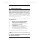
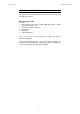
Instruction Manual CyberScan PC5500/ 5000 3 GETTING STARTED 3.1 Connectors (PCD 5500 only) 1. Review the layout and arrangement of the rear connector panel.
Instruction Manual CyberScan PC5500/ 5000 Back Panel of PC 5500/ 5000 4
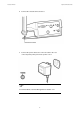
Instruction Manual CyberScan PC5500/ 5000 2. Connect the electrode arm to the base. 3. Connect the power cable to the connector cable to the rear connector panel power jack and to a power source. To connect RS232, see Data Management on Section 17.2.
Instruction Manual CyberScan PC5500/ 5000 3.2 pH Electrodes & Ion Specific Electrodes (PCD5500 & PC5500 only This meter allows you to use two types of pH electrodes: the conventional glass pH electrode and the field effect transistor (FET) pH electrode. If both types of pH electrodes are connected, the meter will read the FET electrode. 1. Carefully remove the protective cover from the end of the electrode.
Instruction Manual CyberScan PC5500/ 5000 3. Rinse and blot-dry (don’t wipe) electrodes between each measurement. Rinse electrodes with distilled or deionized water, or a portion of the next solution to be measured. 4. Between measurements, store conventional pH electrodes storage solution, pH 4 buffer, or KCI solution. Always leave the filling hole of liquid filled combination electrodes open. Refill when the level of solution gets below the manufacturer’s recommended level.
Instruction Manual CyberScan PC5500/ 5000 3.3 Conductivity Probes This meter allows you to use two types of conductivity cells: the 2-cell conductivity cell with dual pin connector and the 4-cell conductivity cell with DIN connector. If both a 2-cell and a 4-cell conductivity probe are connected, the meter will read the 4-cell conductivity probe. 1. Carefully remove the protective cover from the end of the conductivity cell.
Instruction Manual CyberScan PC5500/ 5000 3. Rinse and blot-dry (don’t wipe) probe between each measurement. Rinse probe with distilled or deionized water, or a portion of the next solution to be measured. 4. Between measurements, conductivity probes dry.
Instruction Manual CyberScan PC5500/ 5000 4 USING THE METER EUTECH INSTRUMENTS 11:11 am Touch anywhere to resume 10
Instruction Manual CyberScan PC5500/ 5000 4.1 Touch screen Operation This new CyberScan research benchtop meter operates with a state of art touch screen. The touch screen makes this the easiest meter on the market to operate and care for. When this meter is first plugged in, the STANDBY screen will appear. Touch anywhere on this screen to access the functions of the meter. The buttons on the right side of the screen control all of the functions of the meter.
Instruction Manual CyberScan PC5500/ 5000 4.2 Choosing a channel (for PCD5500 & PC5500 only) Main Screen Channel Screen EUTECH EUTECH pH INSTRUMENTS CyberScan PC 5500 CyberScan PC 5500 mV Select from the options to the right Select from the options to the right Cond setup January 15, 2002 11:11 am Measure pH channel 1 1 9.295 2 ID# 00000 auto buffer ON ATC 25.0°C slope 000.0% mV 0000.0 Buffers Last std: Jan 15 @ 11:11 am January 15, 2002 11:11 am µS/cm channel 1 0.
Instruction Manual CyberScan PC5500/ 5000 The CyberScan PCD5500/ PC5500 are multi-channel meters. With this meter you can switch from channel 1 to channel 2. You can also view both channels at the same time by accessing the dual channel mode. If you set the meter to view both channels, you cannot change the parameters without choosing the screen that you want to modify. The setup parameters for each screen independently of one another. Choosing a channel 1. Touch anywhere on the standby screen.
Instruction Manual CyberScan PC5500/ 5000 4.3 Button Functions The touch screen of your CyberScan bench meter has “buttons” along the right side of the screen that are common to many of the screens. The following indicates the function of these common buttons. This is the standby button and it allows you to access the standby mode. When in standby, the meter will not take measurements. It is in a state of rest.
Instruction Manual CyberScan PC5500/ 5000 std This button accesses the standardization screen from the various measurement modes and initiates standardization of the meter once the standardization screen is accessed. meas This button is the measure button and directs the meter to measure your sample when in the Auto Read function of the pH mode. setup print This button will access the setup screens for the measuring mode that you are currently using.
Instruction Manual CyberScan PC5500/ 5000 5 SYSTEM SETUP System Setup SYSTEM SETUP OPTIONS S - Select Language T - Set Date - Set Time - Set Beeper Status - Set Print Configuration - Set Operator - Set Display Contrast - Display Meter Information - Reset to Factory Defaults 16 edit
Instruction Manual CyberScan PC5500/ 5000 5.
Instruction Manual CyberScan PC5500/ 5000 The system setup function allows you to customise the meter display options to meet your personal preference. Once set, these will rarely need to be changed. To access System Setup 1. Touch anywhere on the standby screen 2. Touch setup on the main screen 3. Touch system on the setup screen The system setup options are now displayed on the screen. To access a System Setup option 1.
Instruction Manual CyberScan PC5500/ 5000 5.
Instruction Manual CyberScan PC5500/ 5000 This option allows you to choose the language in which all prompts and directions will appear on the touch screen. To Select Language 1. Access the select language screen from the system setup screen. The current language is displayed on the screen. 2. Use the arrow keys to highlight the desired language 3. Touch enter to accept the language and return to the system setup screen. OR Touch exit to return to the system setup screen, without making any changes.
Instruction Manual CyberScan PC5500/ 5000 5.
Instruction Manual CyberScan PC5500/ 5000 This screen can be used to set the present date which will be displayed on the measure screens. This date will also be printed on demand and stored in the data storage center of the meter when data is saved. There are two format options for the date: month/ day/ year (M/ D/ Y) or the European format of day/ month/ year (D/ M/ Y) To Set Date 1. Access the Set Date screen from the System Setup screen. The current date and numeric keypad are displayed on the screen.
Instruction Manual CyberScan PC5500/ 5000 5.
Instruction Manual CyberScan PC5500/ 5000 This screen can be used to set the present time which will be displayed on the measure screens. This time will also be printed on demand and stored in the data storage center of the meter when data is saved. There are two formats options for the time. The clock can be set as either a 12 hour clock or a 24 hour clock. To Set Time 1. Access the set time screen from the System Setup screen. The current time and numeric keypad are displayed on the screen. 2.
Instruction Manual CyberScan PC5500/ 5000 5.
Instruction Manual CyberScan PC5500/ 5000 This screen allows you to turn on or off the beeper. You may choose to have an audible signal when the meter recognises that the current measurement is stable, each time a function button is touched and/ or when the set limits of a measurement mode have been exceeded. After stable reading When active, the meter delivers an audible tone each time the meter recognises the current measurement as stable.
Instruction Manual CyberScan PC5500/ 5000 5.6 Select procedural level Select Procedural Level enter 1 Current LEVEL LEVEL 1 - Basic Level 1 LEVEL 2 - Advanced Level 2 Procedural Level 1 January 15, 2002 Temperature 11:11am 25.0°C Electrode Performance 100% Procedural Level 2 January 15, 2002 ID# 00000 ATC auto buffer ON slope mV 27 11:11am 25.0°C 100% 0000.
Instruction Manual CyberScan PC5500/ 5000 This selection screen allows you to choose the amount of information that you want to have displayed on the screen. There are two levels to choose from. Both of the levels provide identical results. The amount of information appearing on the measure screens and the number of setup parameters you can manipulate will vary from Basic to Advanced procedural levels.
Instruction Manual CyberScan PC5500/ 5000 5.
Instruction Manual CyberScan PC5500/ 5000 You can adjust the print configuration of this meter from this screen. The configuration of the following screens must match the configuration of the printer or computer to which the data will be sent. To Set Print Configuration 1. Access the Print Configuration screen from the System Setup screen. The current Print Configuration is displayed on the screen. 2. Use the arrow keys to highlight the configuration option to be modified. 3.
Instruction Manual CyberScan PC5500/ 5000 5.8 Set Baud Rate This configuration option will control the speed at which the data will be transmitted by the printer. This parameter needs to match the baud rate designated by the printer or computer. To Set Baud Rate 1. Access the Set Baud Rate screen from the Set Print Configuration screen. The current baud rate is displayed on the screen. 2. Use the arrow keys to highlight the baud rate option that matches the baud rate of your printer or computer. 3.
Instruction Manual CyberScan PC5500/ 5000 5.9 Set Number of Bits To Set Number of Bits 1. Access the Set number of Bits screen from the Set Print Configuration screen. The current number of bits is displayed on the screen. 2. Touch 7 or 8 to select the number of bits. 3. Touch enter to accept the bit value and return to the Set print Configuration screen. OR Touch exit to return to the Set Point Configuration screen, without making any changes.
Instruction Manual CyberScan PC5500/ 5000 5.10 Set Stop Bits To Set Stop Bits 1. Access the Set Stop Bits screen from the Set Print Configuration screen. The current number of bits is displayed on the screen. 2. Touch 1 or 2 to set the desired number of stop bits. 3. Touch enter to accept the stop bit value and return to the Set Print Configuration screen. OR Touch exit to return to the Set Print Configuration screen, without making any changes.
Instruction Manual CyberScan PC5500/ 5000 5.11 Set Parity To Set Parity 1. Access the Set Parity screen from the Set Print Configuration screen. The current Parity is displayed on the screen. 2. Touch ODD or EVEN or NONE to set the desired parity. 3. Touch enter to accept the parity setting and return to the Set Print Configuration screen. OR Touch exit to return to the Set Print Configuration screen, without making any changes.
Instruction Manual CyberScan PC5500/ 5000 5.12 Set Operator Set Operator enter Current Operator A B C 1 D E F 2 G H I 3 J K L 4 M N O 5 P Q R 6 S T U 7 V W X 8 Y Z - 9 BS / .
Instruction Manual CyberScan PC5500/ 5000 This option allows you to identify the user of the meter. This information can be saved in the meter’s memory. It can also be printed out with measurement data on demand. The operator identification can be up to 9 characters in length. To Set Operator 1. Access the Set Operator screen from the System Setup screen. The current operator identification is displayed on the screen. 2. Touch clear to remove the current operator identification. 3.
Instruction Manual CyberScan PC5500/ 5000 5.
Instruction Manual CyberScan PC5500/ 5000 This option allows you to change the contrast on the screen to improve the readability of the information presented on the screen. The numbering system that appears on the screen is from 0 to 25. The darkest setting is 0 and the lightest setting is 25. To Set Display Contrast 1. Access the Set Display Contrast screen from the System Setup screen. The current display contrast value is displayed on the screen. 2.
Instruction Manual CyberScan PC5500/ 5000 5.14 Display Meter Information This screen displays the model number, serial number and current software revision of your meter. EUTECH INSTRUMENTS 11:11 am Unit Serial Number: Software Revision: XX999XXX 1.
Instruction Manual CyberScan PC5500/ 5000 5.15 Reset to Factory Defaults This screen allows you to reset all functions and setup parameters of the meter of the settings originally programmed at the factory. To Reset to Factory Defaults 1. Access the Reset to Factory Defaults screen from the System Setup screen. 2. Touch Yes to reset all parameters to the original factory default settings. OR Touch NO to return to the System Setup screen, without making any changes.
Instruction Manual CyberScan PC5500/ 5000 6 pH SETUP pH Setup pH SETUP OPTIONS S - Set Sample ID# T - Select Buffer Group - Select Buffer Recognition - Select Auto Read Mode - Set pH Stability Criteria - Set Default Temperature edit - Set Isopotential Point - Set Alarm Limits - Set Print Criteria - Set Print Interval - Set Data Storage Criteria - Set Display Resolution - Set Display Configuration - View Stored Data The operating parameters of the pH mode can be set and controlled from the pH setu
Instruction Manual CyberScan PC5500/ 5000 6.1 Access pH setup EUTECH INSTRUMENTS CyberScan PC 5000 Setup pH pH mV mV Ion Ion Select from the options to the right Select from the options to the right Cond Cond setup system Last std: Jan 15 @ 11:11 am pH Setup There are two ways to access the pH Setup screen. S pH SETUP OPTIONS From the setup screen - Set Sample ID# - Select Buffer Group - Select Buffer Recognition T 1. Touch setup on the main screen.
Instruction Manual CyberScan PC5500/ 5000 EUTECH INSTRUMENTS CyberScan PC 5000 Measure pH channel 1 pH 7.00 mV std meas 7 Ion Select from the options to the right BUFFERS Last std: Jan 15 @ 11:11 am Cond Touch meas to measure sample or Touch std to access standardize setup January 15, 2002 00000 ID# auto buffer ON Last std: Jan 15 @ 11:11 am 11:11am ATC 25.0°C Slope mV NA 0000.0 pH Setup From the pH measure screen S pH SETUP OPTIONS 1.
Instruction Manual CyberScan PC5500/ 5000 6.2 Set Sample ID# Set pH Sample ID# enter Manual ID# A B C 1 D E F 2 G H I 3 J K L 4 M N O 5 P Q R 6 S T U 7 V W X 8 Y Z - 9 BS / .
Instruction Manual CyberScan PC5500/ 5000 When this option is active, each time you touch print on the Measure screen the pH value along with the date/ time/ channel and the sample ID# will be sent to data storage. (for additional information on saved parameters). You can manually enter an alphanumeric identification number of up to 9 characters for any sample or you can have the meter sequentially number your samples beginning at the number of your choice. You may choose to deactivate the sample ID#.
Instruction Manual CyberScan PC5500/ 5000 Set pH Sample ID# enter Sequential ID# 1 2 3 4 5 6 24hr clear 7 8 9 BS 0 .
Instruction Manual CyberScan PC5500/ 5000 Sequential ID# Assignment 1. Access the Set Sample ID# screen from the pH (mV, Ion, Conductivity) Setup screen. 2. Touch seq for sequential ID# assignment. The current ID# is displayed on the screen. 3. Touch clear to delete the current ID#. 4. Use the alphanumeric keypad on the screen to enter the number that you would like your sequential ID# assignment to begin with. Every time you touch print on the measure screen, the ID# will increase by 1.
Instruction Manual CyberScan PC5500/ 5000 6.
Instruction Manual CyberScan PC5500/ 5000 This setup option allows you to select from 3 different buffer groups each containing 5 buffers, for auto buffer recognition. Or you can create a custom group of buffers for auto buffer recognition by touching custom. The 3 existing buffer groups are: USA buffers: European buffers: NIST buffers: 2,4,7,10 and 12 1,3,6, 8 and 10 1.68, 4.01. 6.86. 9.18 and 12.45 To Select Buffer Group 1. Access the select pH buffer group screen from the pH Setup screen.
Instruction Manual CyberScan PC5500/ 5000 6.4 Set pH Custom Buffer Group View pH Custom Buffer Group View pH Custom Buffer Group enter Current BUFFER GROUP Current BUFFER GROUP CUSTOM W CUSTOM X edit edit enter Use keys to display desired buffer group and then touch enter to accept Use keys to display desired buffer group and then touch enter to accept View pH Custom Buffer Group Current BUFFER GROUP enter CUSTOM 1.78 3.
Instruction Manual CyberScan PC5500/ 5000 To Set pH Custom Buffer Group This option allows you to create a custom buffer group of up to 5 buffers to be used for auto buffer recognition. To obtain optimal results, it is important to maintain at least 2 pH units between selected buffers in the custom group. 1. Touch custom on the Set pH Buffer Group screen. The current buffer box will show the current custom buffer group. 2. Touch edit to alter the present group or create a new custom buffer group.
Instruction Manual CyberScan PC5500/ 5000 6.5 Select Buffer Recognition This option allows you to select automatic buffer recognition or manual buffer recognition when standardizing. With the Automatic buffer recognition activated, the meter will automatically recognise the buffers from the chosen buffer group and accept them when the meter recognises the reading as stable. When in the manual buffer recognition mode, you must enter the buffer value during the standardization procedure.
Instruction Manual CyberScan PC5500/ 5000 6.6 Select Auto Read Mode You can use this meter when the Auto Read Mode function is active or when it is inactive. When the Auto Read function is active, the meter will lock onto a reading when the meter recognises it as stable. The meter will not deviate from this reading until meas is touched.
Instruction Manual CyberScan PC5500/ 5000 6.
Instruction Manual CyberScan PC5500/ 5000 This setup screen allows you to determine how quickly the meter will respond to electrode drift. There are 3 speed settings: fast, medium and slow. To set pH Stability Criteria 1. Access the Set pH Stability Criteria screen from the pH (Ion) Setup screen. The current stability criteria are displayed on the screen. 2. Use the arrow keys to highlight the desired stability criteria. 3.
Instruction Manual CyberScan PC5500/ 5000 6.8 Set Default Temperature Set pH Default Temperature enter Current DEFAULT 25.0°C 1 2 3 4 5 6 7 8 9 clear BS 0 .
Instruction Manual CyberScan PC5500/ 5000 It is a well known fact that pH is a temperature dependent measurement. The factory default setting is 25. if you are taking the pH of a solution that is not 25 and you are not using an Automatic Temperature Compensation (ATC)( probe, then you should meter the temperature value of that solution in order to get the correct pH value. The current default temperature setting will be displayed when the Set Default Temperature screen is displayed.
Instruction Manual CyberScan PC5500/ 5000 6.9 Set Isopotential Point Set pH Isopotential Point enter Current ISO POINT 0.0 mV 1 2 3 4 5 6 7 8 9 BS 0 .
Instruction Manual CyberScan PC5500/ 5000 The Isopotential point is the millivolts reading for an electrode at which temperature has no effect on the measurement. pH electrodes are constructed so that the isopotential point is theoretically zero millivolts. This is very close to a pH of 7. Most pH electrodes do not achieve this value precisely. However, they are close enough so that it is not usually necessary to use an isopotential point other than zero.
Instruction Manual CyberScan PC5500/ 5000 6.10 Set Alarm Limits Set pH Limits S Current LIMITS pH Alarm OFF pH Minimum T 0.00 pH Maximum 14.00 edit Set Ion Limits Set mV Limits Current LIMITS Current LIMITS mV Alarm OFF Ion Alarm OFF mV Minimum -1800.0 Ion Minimum mV Maximum 1800.0 Ion Maximum Set Cond Limits Current LIMITS Conductivity Alarm Conductivity Minimum Conductivity Maximum 60 OFF 0.00 1.00E6 0.00 1.
Instruction Manual CyberScan PC5500/ 5000 This option allows you to set alarm limits for the pH measuring mode. If the pH value of the measurement is outside the boundaries set by the minimum and maximum limits, an audible alarm and/ or a visual warning will appear to let you know that your sample measurement was outside of the set limits. To Set Alarm Limits 1. Access the Set Alarm Limits screen from the pH (mV, Ion, Conductivity) Setup screen. The current alarm limits are displayed on the screen. 2.
Instruction Manual CyberScan PC5500/ 5000 6.
Instruction Manual CyberScan PC5500/ 5000 This screen allows you to select which criteria are printed with the measurement when you print the data or send it to the computer. The status of the current print criteria is displayed on the screen. The criteria option is active if “ON” appears to the right of the option. It is inactive if “OFF” appears to the right of the option. Any active criteria will be printed on demand. To Set Print Criteria 1.
Instruction Manual CyberScan PC5500/ 5000 6.12 Set Print Interval Set pH Print Interval enter Current INTERVAL manual 1 2 3 4 5 6 7 8 9 timed BS 0 . You have three options for setting the print interval: manual printing, stable reading printing, and timed interval printing. For manual printing of data In this mode, data is printed only when you touch print on the pH (mV, Ion, Conductivity) Measure screen. 1.
Instruction Manual CyberScan PC5500/ 5000 For stable reading printed In this mode, data is printed every time the meter recognises the current pH (mV, Ion, Conductivity) measurement as stable. 1. Access the Set Print Interval screen from the pH (mV, Ion, Conductivity) Setup screen. The current print interval is displayed on the screen. 2. Touch stable to set the meter for stable reading printing. 3. Touch enter to accept the print interval mode and return to the pH (mV, Ion, Conductivity) Setup screen.
Instruction Manual CyberScan PC5500/ 5000 6.
Instruction Manual CyberScan PC5500/ 5000 This screen allows you to select what criteria are stored in the meter’s memory with the measurement when you save the data. Data is stored only if a Sample ID# has been assigned. The status of the current data storage criteria is displayed on the screen. The criteria option is active if “ON” appears to the right on the screen. It is inactive if “OFF” appears to the right of the option.
Instruction Manual CyberScan PC5500/ 5000 6.14 Set Display Resolution Set pH Display Resolution enter Current RESOLUTION X.XX X.X X.XX Select desired display resolution and then touch enter to accept 68 X.
Instruction Manual CyberScan PC5500/ 5000 This mode allows you to set the display resolution that you desire on the screen. You have the choice of one, two or three decimal places. To Set Display Resolution 1. Access the set display resolution screen from the pH Setup screen. The current Display Resolution is displayed on the screen. 2. Touch X.X, X.XX, X.XXX to select the desired resolution of the display. This will be the format in which your measurement will be displayed. 3.
Instruction Manual CyberScan PC5500/ 5000 6.
Instruction Manual CyberScan PC5500/ 5000 This function will allow you to choose what information you would like to be displayed on the pH Measure screen, particularly the information contained in the data box at the bottom of that screen. To Set Display Configuration 1. Access the Set Display Configuration screen from the pH (mV, Ion, Conductivity) Setup screen. The current display configuration is displayed on the screen. 2.
Instruction Manual CyberScan PC5500/ 5000 6.
Instruction Manual CyberScan PC5500/ 5000 This meter has memory capacity of up to 250 data points (1000 data points for PCD5500). The View Stored Data screen allows you to sort and look at specific data points. The stored data can be sorted by sample identification number, date or operator identification number. To View Stored Data 1. Access the view stored data screen from the pH (mV, Ion, Conductivity) setup screen.
Instruction Manual CyberScan PC5500/ 5000 To sort by Date 1. Access the Date sort option from the View Stored Data screen. 2. Touch clear to delete the current date. 3. Use the numeric keypad to enter the date on which the data points you want to view were saved. Be sure to use/ to separate the month, the day and the year. 4. Touch enter. All data will be sorted by the meter and the first data point displayed on the screen will be the most recent data point saved under the selected Date. 5.
Instruction Manual CyberScan PC5500/ 5000 If an operator ID is entered and no data points are stored with that operator ID, you will see a message indicating the operator ID was not found. Touch OK to return to the operator ID keypad and enter a new operator ID. Even if you do not know the appropriate information to access a specific data point, you can access the stored data through any of the sort options. Highlight the sort option of interest and touch enter to access the sort screen.
Instruction Manual CyberScan PC5500/ 5000 7 mV SETUP mV Setup (channel 1) mV SETUP OPTIONS S - Set Sample ID# T - Set Alarm Limits - Set Print Criteria - Set Print Interval - Set Data Storage Criteria - Set Display Resolution edit - Set Display Configuration - View Stored Data 76
Instruction Manual CyberScan PC5500/ 5000 7.1 Access mV Setup Setup EUTECH INSTRUMENTS pH pH CyberScan PC 5500 mV mV Ion Ion Select from the options to the right Select from the options to the right Cond Cond setup system Last std: Jan 15 @ 11:11 am mV Setup (channel 1) mV SETUP OPTIONS There are two ways to access the mV Setup screen. S From the setup screen - Se t Sample ID# - Set Alarm Limits - Set Print Criteria T 1. Touch setup on the main screen.
Instruction Manual CyberScan PC5500/ 5000 Measure EUTECH INSTRUMENTS pH CyberScan PC 5000 mV channel 1 abs mV 0.0 REL meas Ion Touch meas to measure sample Select from the options to the right or Touch REL for Relative mV reading setup January 15, 2002 ID# 00000 11:11am ATC 25.0°C Last std: Jan 15 @ 11:11 am From the Setup screen mV Setup (channel 1) 1. Touch setup on the mV Measure screen. The mV Setup screen is now displayed. Touch mV on the main screen to access the millivolts mode.
Instruction Manual CyberScan PC5500/ 5000 To Set Sample ID# When this option is active, each time you touch print on the Measure screen the mV value along with the date/time/channel and the sample ID# will be sent to data storage. You can manually enter an alphanumeric identification number of up to 9 characters for any sample, or you can have the meter sequentially number your samples beginning at the number of your choice. You may also choose to deactivate the sample ID#.
Instruction Manual CyberScan PC5500/ 5000 To Set Print Interval You have three options for setting the print interval: manual printing, stable reading printing and timed interval printing. The mV Print Interval is set the same way as previously described in pH setup. See page 64 for instructions. To Set Data Storage Criteria This screen allows you to select what criteria are stored in the meter’s memory with the measurement when you save the data.
Instruction Manual CyberScan PC5500/ 5000 7.2 Set Display Resolution Set mV Display Resolution enter Current RESOLUTION X.XX X.X X.
Instruction Manual CyberScan PC5500/ 5000 To Set Display Resolution This mode allows you to set the display resolution that you desire on the screen. You have the choice of zero or one decimal place. 1. Access the set display resolution screen from the mV setup screen. The current display resolution is displayed on the screen. 2. Touch X or X.X to select the resolution of the display that you desire. This will be the format in which your measurement will be displayed. 3.
Instruction Manual CyberScan PC5500/ 5000 8 ION SETUP Ion Setup (channel 1) ISE SETUP OPTIONS S - Set Sample ID# T - Select Ion Method - Select Measurement Units - Select Auto Read Mode - Set Ion Stability Criteria - Set Default Temperature edit - Set Isopotential Point - Set Alarm Limits - Set Print Criteria - Set Print Interval - Set Data Storage Criteria - Set Significant Digits - Set Display Configuration - View Stored Data The operating parameters of the ion mode can be set and controlled fr
Instruction Manual CyberScan PC5500/ 5000 8.1 Access Ion Setup EUTECH INSTRUMENTS Setup pH pH mV mV Ion Ion Select from the options to the right Select from the options to the right Ion Setup (channel 1) ISE SETUP OPTIONS Cond Cond setup system There are two ways to access the Ion Setup screen S From the Setup screen - Set Sample ID - Select Ion Method - Select Measurement Units T 1. Touch setup on the main screen. Then touch Ion on the Ion Setup screen.
Instruction Manual CyberScan PC5500/ 5000 Measure EUTECH INSTRUMENTS pH CyberScan PC 5000 channel 1 ppm 0.0 mV std meas STANDARDS Last std: Jan 15 @ 11:11 am Ion Select from the options to the right setup Touch std to access standardize mode Cond setup January 15, 2002 ID# 00000 Nh3 11:11am ATC Last std: Jan 15 @ 11:11 am mV From the Ion Measure screen 25.0°C Slope NA 0000.0 Ion Setup S ISE SETUP OPTIONS 4. Touch Ion on the main screen to access the Ion mode.
Instruction Manual CyberScan PC5500/ 5000 8.2 Select Ion Method To Set Sample ID# When this option is active, each time you touch print on the Measure screen the ion concentration value along with date/ time/ channel and the sample ID# will be sent to data storage. You can manually enter an alphanumeric identification number of up to 9 characters for any sample or you can have the meter sequentially number your samples beginning at the number of your choice.
Instruction Manual CyberScan PC5500/ 5000 Direct Reading with Standards The direct reading method is the most common method of ion measurement. When using this method, you will use standards of known values to standardize the meter with ion standards. An ionic strength adjuster (ISA) is added to both the standards and the sample. 2 to 5 standards are used to standardize the meter. The standards should bracket the expected value of the sample.
Instruction Manual CyberScan PC5500/ 5000 Analate Subtraction The analate subtraction method is particularly useful in the event that there is no ion specific electrode available to directly measure the concentration of the ion of interest. This method employs the addition of a sample of the ion of interest to a standard containing a different ion of known concentration.
Instruction Manual CyberScan PC5500/ 5000 To Select Auto Read Mode You can use this meter when the Auto Read Mode function is active or when it is inactive. When the Auto Read function is active, the meter will lock onto a reading when the meter recognises it as stable. The meter will not deviate from this reading until meas is touched. If the auto Read function is inactive, then the meter will continuously monitor the concentration of the ion of interest.
Instruction Manual CyberScan PC5500/ 5000 8.4 Select Electrode Type This screen allows you to select the type of electrode that is specific for your ion of interest. Your choice of electrode informs the meter which default slope to use in the calculations made for the electrode efficiency and sample concentration. Once you have selected an electrode, you will not be required to enter the default slope numerically.
Instruction Manual CyberScan PC5500/ 5000 To Set Isopotential point The Isopotential point is the millivolts reading for an electrode at which temperature has no effect on the measurement. Ion selective electrodes, unlike pH electrodes, are not designed to achieve any particular isopotential point. If samples and standards are at different temperatures when performing ISE experiments, it will be necessary to experimentally determine the isopotential point of your own Ion Specific Electrode.
Instruction Manual CyberScan PC5500/ 5000 8.
Instruction Manual CyberScan PC5500/ 5000 This option allows you to select the number of significant figures that will be used when reporting your ion measurement. You have the choice of one, two or three significant digits. To Set Significant Digits 1. Access the Set Significant Digits screen from the Ion Setup screen. The current Significant Digits is displayed on the screen. 2. Touch 1, 2 or 3 to select the desired significant digits. 3.
Instruction Manual CyberScan PC5500/ 5000 9 CONDUCTIVITY SETUP The operating parameters of the conductivity mode can be set and controlled from the Conductivity Setup screen. The following sections will guide you through the various options available for the conductivity setup mode.
Instruction Manual CyberScan PC5500/ 5000 9.1 Access the Conductivity Setup EUTECH INSTRUMENTS CyberScan PC 5000 Setup pH pH mV mV Ion Ion Select from the options to the right Select from the options to the right Cond Cond setup system Last std: Jan 15 @ 11:11 am Conductivity Setup (channel 1) CONDUCTIVITY SETUP OPTIONS There are two ways to access the Conductivity Setup screen. S - Set Sample ID - Select Conductivity Units - Select Cell Constant From the Setup screen T 1.
Instruction Manual CyberScan PC5500/ 5000 EUTECH INSTRUMENTS Measure - Conductivity pH channel 1 µS/cm 0.010 mV STANDARD std meas Last std: Jan 15 @ 11:11 am Ion setup Touch meas to measure sample or Select from the options to the right Cond Touch std to access standardize mode setup January 15, 2002 ID# From the Conductivity Measure screen 00000 11:11am ATC 25.0°C Ref 25°C Co 0.00%/°C Conductivity Setup (channel 1) CONDUCTIVITY SETUP OPTIONS S - Set Sample ID 1.
Instruction Manual CyberScan PC5500/ 5000 To Set Sample ID# When this option is active, each time you touch print on the Measure screen the mV value along with the date/time/channel and the sample ID# will be sent to data storage. You can manually enter an alphanumeric identification number of up to 9 characters for any sample, or you can have the meter sequentially number your samples beginning at the number of your choice. You may also choose to deactivate the sample ID#.
Instruction Manual CyberScan PC5500/ 5000 Select Conductivity Units Current UNIT ppm Conductivity µS/cm Salinity ppt Total Dissolved Solids Resistivity S ppm ohm .
Instruction Manual CyberScan PC5500/ 5000 9.2 Select Cell Constant Select Cond Cell Constant Current CONSTANT 10.0/cm S 0.10/cm 1.00/ cm T 10.
Instruction Manual CyberScan PC5500/ 5000 This screen allows you to select the appropriate cell constant of the conductivity cell that you are using. There are three cell constants to choose from. Each is used for a different range of conductivity. The following indicates the optimal conductivity range for the conductivity cells. Optimal Conductivity Range Cell Constant 2-cell 4-cell 0.1 0.5 to 200 µS/ cm Not Available 1.0 0.01 to 2 mS/ cm 0.01 to 20 mS/ cm 10.
Instruction Manual CyberScan PC5500/ 5000 9.
Instruction Manual CyberScan PC5500/ 5000 To Select Reference Temperature This screen allows you to select the reference temperature to be used in the determination of the conductivity of your sample. 1. Access the Select Reference Temperature screen from the Conductivity Setup screen. The current Reference Temperature is displayed. 2. Touch C or F to select the desired Temperature units for the reference temperature. 3. Use the arrow keys to highlight the desired reference temperature 4.
Instruction Manual CyberScan PC5500/ 5000 9.4 Set Temperature Coefficient Set Cond Temperature Coeff enter Current COEFF 0.00%/°C 1 2 3 4 5 6 7 8 9 clear BS 0 .
Instruction Manual CyberScan PC5500/ 5000 The temperature coefficient is a value that reflects the degree to which the sample’s conductivity is effected by temperature changes. The meter will use the set temperature coefficient along with the measured temperature provided by the ATC probe to calculate what the conductivity would be at the selected reference temperature. If no ATC probe is being used, the meter will use the set default temperature in the calculation. To Set Temperature Coefficient 1.
Instruction Manual CyberScan PC5500/ 5000 9.5 Perform Replatinization Replatinize 5 min Current TIME 1 2 3 4 5 6 7 8 9 BS 0 . Replatinize Replatinize Electrode You are about to replatinize an electrode 5:00 Place the electrode in replarinizing solution and then touch START to begin. Touch EXIT to cancel now.
Instruction Manual CyberScan PC5500/ 5000 Replatinization is the process of replacing the platinum on the surfaces of the 2-cell conductivity probes that may flake or wear off over time. The platinum on the surface of the probe is used to increase the surface area of the measuring surface resulting in decreased polarization error. Replatinization is a relatively quick procedure to perform, taking no more than 5 minutes in most cases.
Instruction Manual CyberScan PC5500/ 5000 To Set Alarm Limits This option allows you to set alarm limits for the Conductivity measuring mode. If the Conductivity value of the measurement is outside of the boundaries set by the upper and lower limits, an audible alarm and/ or a visual warning will appear to let you know that your sample measurement was outside of the set limits. The Conductivity alarm limits are set the same way as previously described in pH setup. See page 60 for instructions.
Instruction Manual CyberScan PC5500/ 5000 To Set Data Storage Criteria This screen allows you to select what criteria are stored in the meter’s memory with the measurement when you save the data. The status of the current data storage criteria is displayed on the screen. The criteria option is active if “ON” appears to the right of the option. It is inactive if “OFF” appears to the right of the option. All storage criteria will be stored in the meter’s memory with the measurement.
Instruction Manual CyberScan PC5500/ 5000 9.
Instruction Manual CyberScan PC5500/ 5000 This option allows you to select the number of significant figures that will be used when reporting you conductivity measurement. You have the choice of one, two or three significant digits. To set Significant Digits 1. Access the Set Significant Digits screen from the conductivity Setup screen. The current Significant Digits are displayed on the screen. 2. Touch 1, 2 or 3 to select the desired significant digits. 3.
Instruction Manual CyberScan PC5500/ 5000 10 pH OPERATION Measure pH channel 1 7.00 4 7 10 Buffers Last std: Jan 15 @ 11:11 am Touch meas to measure sample or Touch std to standardize January 15, 2002 ID# auto buffer 00000 ON 11:11am ATC 25.0°C slope mV 100% 0000.
Instruction Manual CyberScan PC5500/ 5000 In this mode, you will able to measure the pH of a wide variety of samples. Before measuring pH, you will need to standardize the meter using buffers with known pH values. It is good practice to standardize the meter frequently using a minimum of two buffers. Using two buffers allows the meter to calculate and display an actual slope for the electrode, and therefore produce more accurate measurements.
Instruction Manual CyberScan PC5500/ 5000 10.1 Standardizing Measure pH channel 1 7.00 std meas STABLE 4 7 Buffers Last std: Jan 15 @ 11:11 am Touch meas to measure sample or Touch std to standardize January 15, 2002 00000 ID# auto buffer ON 11:11am ATC 25.0°C slope 100% mV 0000.0 Standardize pH channel 1 7.
Instruction Manual CyberScan PC5500/ 5000 To Standardize the meter with Auto Buffer Recognition 1. Touch STD on the pH measure screen to access the standardized screen 2. Touch clear to delete a previous standardization. All pH standardization values will be cleared. The meter will remain on the standardization screen at this point. OR If the screen says “Not standardized” proceed to step 3. 3.
Instruction Manual CyberScan PC5500/ 5000 Standardize pH std channel 1 7.00 4 7 meas 10 Buffers Last std: Jan 15 @ 11:11 am USA Current BUFFER GROUP Touch clear to delete previous buffers Insert electrode into buffer and stir Touch std to standardize new buffer January 15, 2002 00000 ID# auto buffer ON 11:11am ATC 25.0°C slope 100% mV 0000.0 Standardize std pH channel 1 Enter pH meas STABLE 1 STND 2 3 4 5 6 7 8 9 Not Standardized Touch meas to measure sample or - 0 .
Instruction Manual CyberScan PC5500/ 5000 To standardize the meter with Manual Buffer Recognition 1. Touch std on the pH measure screen to access the standardize screen 2. Touch clear to delete a previous standardization. All pH standardization values will be cleared. The meter will remain on the standardization screen at this point. OR If the screen says “Not Standardization” proceed to step 3. 3. Immerse your rinsed electrode(s) in a buffer solution and stir gently. 4.
Instruction Manual CyberScan PC5500/ 5000 10.2 pH Measurements Measure pH channel 1 7.00 4 7 10 Buffers Last std: Jan 15 @ 11:11 am Touch meas to measure sample or Touch std to standardize January 15, 2002 ID# auto buffer 00000 ON 11:11am ATC 25.0°C slope 100% mV 0000.
Instruction Manual CyberScan PC5500/ 5000 The measure screen provides readout of the current sample measurement. You can use this meter when the auto read function is active or when it is inactive. When the auto read function is active, the meter will lock onto a reading when the meter recognises it as stable. The meter will not deviate from this reading until meas is touched.
Instruction Manual CyberScan PC5500/ 5000 11 mV OPERATION This mode is used to measure oxidation/ reduction potential (ORP/redox), perform titration and to verify the function of the meter. The mV measure function allows you to continuously monitor the mV potential of the electrodes in use. This can be done in either absolute or relative mV. In the millivolts mode, the current millivolts output from the electrodes being used is monitored and displayed on the screen.
Instruction Manual CyberScan PC5500/ 5000 11.1 mV Measurement In the mV mode, you will be able to make measurements in either absolute or relative millivolts, access the mV Setup screens and print your results to a printer or a computer. Connect the electrodes you will be using to the meter. See page 3 for details. Absolute mV measurements 1. Access the mV measure screen from the main screen 2. Touch ABS to access the Absolute mV screen. 3. Immerse your rinsed electrode(s) in the sample and stir gently.
Instruction Manual CyberScan PC5500/ 5000 12 ION OPERATION Measure - Ion std ppm channel 1 17 10.0 100 STNDS Last std: Jan 15 @ 11:11 am Touch meas to measure sample or Touch std to access standardize mode or measure blank January 15, 2002 ID# Nh3 00000 11:11am ATC 25.0°C slope 102.2% mV 0.
Instruction Manual CyberScan PC5500/ 5000 This CyberScan meter offers you unparalled versatility with respect to ion analysis. You can choose one of the 6 methods of analysis, the specific electrode you will be working with and also the units that you would like the meter to use when reporting the ion concentration. The Ion Measure screen displays the direct readout of sample concentration in the desired units, as well as the time and date of the last calibration.
Instruction Manual CyberScan PC5500/ 5000 12.1 Direct Reading Methods Standardize - Ion ppm Standardize - Ion channel 1 --10.
Instruction Manual CyberScan PC5500/ 5000 There are two direct reading methods. Direct Reading with standards and Direct Reading with Blank Offset. These types of measurements allow you to directly read the concentration of your sample after standardizing the meter with ion standards of known values or blank values. Direct Reading Standards This is the most common method of ion measurement.
Instruction Manual CyberScan PC5500/ 5000 Measuring ion concentration in the Direct Reading with Standards Mode With Auto Read on 1. Add Ionic strength adjuster to the sample. 2. Immerse the ion selective electrode in the stirring sample. 3. Touch meas to begin measuring your sample. The meter will accept the reading and display STABLE when the measurement meets the selected stability criteria. The measure screen will fix onto this measurement and will not deviate until meas is touched. 4.
Instruction Manual CyberScan PC5500/ 5000 Standardize - Ion Standardize - Ion ppm channel 1 --- std std ppm ISE Standardize meas meas You have selected Direct Reading with Blank offset operation. STND Is this reading a STANDARD or BLANK? setup STND setup Not Standardized clear Touch meas toSTND measure sample Insert electrode into standard and stir ID# Touch std to access standardize mode 11:11am 00000 Nh3 BLK ATC 25.0°C slope NA mV 0.
Instruction Manual CyberScan PC5500/ 5000 Direct Reading with Blank Offset This method presents you with the ability to measure samples with low level concentrations of the ion of interest. It eliminates background interference by subtracting the value of a blank concentration from the value for the sample. See ISE theory on page 160. To Standardize the Meter You will need to standardize the meter with one blank and a minimum of two standards. 1.
Instruction Manual CyberScan PC5500/ 5000 If you touched STND 8. Use the keypad to enter the value of the standard. 9. Touch enter to accept the value. The meter will accept the standard value when it recognises the reading as stable. 10. Repeat steps 4-7 with additional standards or steps 4-7 and 11 with a blank sample. If you touched BLANK 11. The meter will return to the Ion measure screen and a beaker icon labeled blank will be displayed.
Instruction Manual CyberScan PC5500/ 5000 12.2 Incremental Methods Standardize - Ion ppm Standardize - Ion channel 1 --10.
Instruction Manual CyberScan PC5500/ 5000 The incremental methods which include known addition, known subtraction, analate addition and analate subtraction and are particularly useful with samples containing complex ionic backgrounds which cannot be matched in standards. They are also useful with occasional samples whose temperatures vary. More information on these methods is available in the ISE Theory Section, page 160.
Instruction Manual CyberScan PC5500/ 5000 12.3 Known Addition Method Measure - Ion Measure - Ion mV std channel 1 0.0 1.00 10.0 mV std channel 1 0.0 KA KA 100 setup setup STND STND Last std: Jan 15 @ 11:11am Not standardized Insert electrode into standard and stir Touch std to access standardize mode January 15, 2002 ID# 00000 NH3 KA Touch std to standardize new standard or measure blank January 15, 2002 11:11am ATC 25.0°C slope 102.2% mV 00000 ID# NH3 KA 11:11am ATC 25.
Instruction Manual CyberScan PC5500/ 5000 Standardize - Ion Standardize - Ion std mV std mV channel 1 channel 1 Concentration ISA Volume meas STABLE 1 STND 2 3 4 5 6 7 8 9 - exit 3 4 5 6 7 8 9 . - or 0 . Touch std to access standardize mode enter BS Known Addition Result 12.2 Calculated Slope: Reading 1: Reading 2: Sample Volume: Standard Volume: ISA Volume: Standard Concentration: ppm 58 mV 222.7 mV 200.
Instruction Manual CyberScan PC5500/ 5000 Measuring Ion Concentration in Samples Using the Incremental Methods When performing known addition, you will add an aliquot of standard solution containing the ionic species of interest to a known volume of your sample. The mV readings of the sample can then be calculated based upon the difference in the mV readings. The use of the incremental methods requires that certain parameters be identified.
Instruction Manual CyberScan PC5500/ 5000 To take a measurement 1. Immerse the ion selective electrode in a known volume of the sample solution. 2. Stir the sample. 3. Touch KA to take the first mV reading of sample. Wait for the reading to stabilize (STABLE will appear). OR Touch KA to accept the current reading. 4. Add a known volume of standard solution to the sample. 5. Touch KA to take the second mV reading of sample. Wait for the reading to stabilize (STABLE will appear).
Instruction Manual CyberScan PC5500/ 5000 12.4 Known Subtraction Method The procedure for known subtraction is very similar to that for known addition method. An aliquot of standard is added to a known volume of the sample. The difference is that the standard does not contain the same ionic species that you are trying to measure in the sample. Instead, it contains an ion that will complex or precipitate the ion of interest, removing it from the sample.
Instruction Manual CyberScan PC5500/ 5000 10. Use the keypad to enter the concentration of the standard solution added to the sample. 11. Touch enter to accept the value. 12. Use the keypad to enter the concentration of the standard solution added to the sample 13. Touch enter to accept the value. Your Known Subtraction result is now displayed. 14. Touch print to send the data to memory if sample ID# has been assigned or to print the data on the screen.
Instruction Manual CyberScan PC5500/ 5000 12.5 Analate addition The analate addition method is useful when your sample is at an elevated temperature and you want to negate the effect that temperature will have on the concentration calculation. This method is also useful if you have only a small amount of sample available. The analate addition method differs only slightly from the known addition method.
Instruction Manual CyberScan PC5500/ 5000 10. Use the keypad to enter the concentration of the standard solution added to the sample. 11. Touch enter to accept the value. 12. Use the keypad to enter the concentration of the standard solution added to the sample 13. Touch enter to accept the value. Your Analate Addition result is now displayed. 14. Touch print to send the data to memory if sample ID# has been assigned or to print the data on the screen.
Instruction Manual CyberScan PC5500/ 5000 12.6 Analate Subtraction The analate subtraction method is useful when no ion specific electrode is available to measure the ion of interest directly. Like known subtraction the sample and the standard contain different ionic species. However, the ion being measured is in the standard and not in the sample. The reduction of free ions in the standard solution is proportional to the concentration of the ion of interest in the sample. See ISE theory page 160.
Instruction Manual CyberScan PC5500/ 5000 10. Use the keypad to enter the concentration of the standard solution added to the sample. 11. Touch enter to accept the value. 12. Use the keypad to enter the concentration of the standard solution added to the sample 13. Touch enter to accept the value. Your Analate Addition result is now displayed. 14. Touch print to send the data to memory if sample ID# has been assigned or to print the data on the screen.
Instruction Manual CyberScan PC5500/ 5000 13 CONDUCTIVITY OPERATION Measure - Conductivity std µS/cm channel 1 0.010 STND Last std: Jan 15 @ 11:11 am Touch std to access standardize mode January 15, 2002 ID# 00000 11:11am ATC 25.0°C Ref 25.0°C Co 5.00%/°C The meter will automatically convert conductivity values to salinity, total dissolved solids (TDS), or resistivity.
Instruction Manual CyberScan PC5500/ 5000 This mode allows you to measure the conductivity of solutions. Conductance is a value associated with the ability of primarily aqueous solutions to carry an electrical current. The presence of ions in an aqueous solution increases the solution’s ability to carry an electrical current. Impurities in the solution, such as metals, dissolved soil, etc. increases the ion content of the solution.
Instruction Manual CyberScan PC5500/ 5000 13.1 Conductivity Standardization Standardize - Conductivity µS/cm Standardize - Conductivity std channel 1 0.010 µS/cm channel 1 0.010 meas std meas 10.
Instruction Manual CyberScan PC5500/ 5000 To “standardize” your conductivity probe in the Advanced Level of Operation 1. Access the conductivity Setup screen and verify the values for the nominal cell constant of the probe, the reference temperature and the temperature coefficient. Also, verify that the meter is set for the uS/cm units. 2. Touch std on the Conductivity Measure screen to access the Conductivity Standardization screen. 3.
Instruction Manual CyberScan PC5500/ 5000 To “standardize” your Conductivity Probe in the Basic Level of Operation At the Basic Procedural level the only setup options that you can access are the Cell Constant, the Print Interval and the number of Significant Digits. If you need to change any other parameter such as reference temperature or temperature coefficient you will need to set the Procedural Level to Advanced in the System setup screen.
Instruction Manual CyberScan PC5500/ 5000 13.2 Measurement Measure - Conductivity std µS/cm channel 1 0.010 STND Last std: Jan 15 @ 11:11 am Touch std to access standardize mode January 15, 2002 ID# 00000 11:11am ATC 25.0°C Ref 25.0°C Co 5.
Instruction Manual CyberScan PC5500/ 5000 Once an exact cell constant has been established, the meter is ready for sample measurements. 1. Immerse the conductivity cell and ATC probe into the sample solution. The immersion depth should be enough to cover the vent holes on the electrode. 2. Stir the solution with the electrode briefly and then let the electrode sit still in the solution. 3. Observe and record the measurement value when it appears to be stable (STABLE will appear).
Instruction Manual CyberScan PC5500/ 5000 14 CLEANING The touch screen should be kept as clean as possible to preserve optical properties. Attempt to keep the screen free of dirt, dust fingerprints, etc. long term contact with abrasive materials will scratch the surface, and impair image quality. To clean, use a damp nonabrasive cloth towel and any commercially available window cleaner. The cleaning solution should be applied to the towel rather than the surface of the touch screen.
Instruction Manual CyberScan PC5500/ 5000 15 TROUBLE SHOOTING Your CyberScan meter contains many error messages to provide aid should trouble occur with a measurement or meter operation (touch pad and input errors). The messages are accompanied by a brief description of the error, and in some cases advice on how to correct it. An example of an error message is: Bad Electrode Slope The electrode you have standardized has a slope which is out of the normally acceptable range of 90% to 102%.
Instruction Manual CyberScan PC5500/ 5000 16 COMPLIANCE Notice of compliance Warning: this meter generates uses and can radiate radio frequency energy. If not installed and used properly, that is in strict accordance with the manufacturer’s instructions, it may cause interference to radio communications.
Instruction Manual CyberScan PC5500/ 5000 17 APPENDIX 17.1 Determining Isopotential Points Experimentally The isopotential point of an electrode system is the point at which electrode potential is unaffected by a change in temperature. The coordinates of this point would be coincident with the system’s Zero Potential Point (pXiso, Eo). In practical systems, however, this coincidence rarely occurs, and for some systems, there is no true Isopotential Point but a general Isopotential area.
Instruction Manual CyberScan PC5500/ 5000 17.2 Data Management Your CyberScan meter is equipped with an RS-232 output port for sending measurement readings to a printer or computer. To use the meter with a printer or a computer, the printer or computer must have an RS-232 part, also. It should be capable of receiving data within the following guidelines.
Instruction Manual CyberScan PC5500/ 5000 17.3 Factory Default Settings The following is the list of factory default settings for this CyberScan meter. You can reset your meter to the factory default settings by accessing the Reset to Factory Defaults from the System Setup screen.
Instruction Manual CyberScan PC5500/ 5000 Mode Screen Default Setting ISE Display configuration Print configuration Data configuration Sample ID# Isopotential Point Print interval Display resolution Auto Read Mode Temperature Units Default Temperature Stability Criteria Default Slope ISE method Units Electrode alarm limits alarm limit low alarm limit high All parameters ON All parameters ON All parameters ON None 0 mV manual 2 significant digits OFF Celsius 25.0°C Medium 59.
Instruction Manual CyberScan PC5500/ 5000 17.4 pH Theory Since its introduction by the Danish Chemist Sorensen in 1909, pH measurement has become one of the most commonly used and important measurements in both laboratory and industry settings. pH measurement and control is vital to a wide array of endeavors including municipal and industrial wastewater treatment, and textile, pharmaceutical, food and pH. Most organisms can exit only within a narrow pH range.
Instruction Manual CyberScan PC5500/ 5000 At 25 °C in pure water, the concentration of hydronium ions is extremely small, 1 X 10⁻⁷ Moles/liter, and balanced by an equal concentration of hydroxyl ions.
Instruction Manual CyberScan PC5500/ 5000 pH Measurement The pH value of a sample can be determined in several ways. These include the use of organic dyes which change colour in certain pH ranges. The dyes can be added directly to the solution or impregnated onto paper which may be dipped into the solution. At best, these “colorimetric” methods yield approximate pH values, often with an accuracy of plus or minus 0.5 pH units.
Instruction Manual CyberScan PC5500/ 5000 Temperature 4.01 6.86 9.18 0 10 20 25 30 40 50 4.003 3.998 4.002 4.008 4.015 4.035 4.060 6.984 6.923 6.881 6.865 6.853 6.838 6.833 9.464 9.332 9.225 9.180 9.139 9.068 9.011 pH Electrodes The electrode system consists of two half cells; a pH indicating electrode, which is primarily responsive to the acidity (the hydronium ion concentration) of a solution, and a reference electrode, which provides a constant voltage and completes the electrical circuit.
Instruction Manual CyberScan PC5500/ 5000 Reference electrodes typically consist of three elements: an internal reference electrode, a filling solution, and a reference junction through which the filling solution can “flow”, and provide electrical contact with the sample and the internal reference electrode. The most convenient internal reference electrodes are made from a metal (such as silver or mercury) and its sparingly soluble salt (silver chloride or mercurous chloride).
Instruction Manual CyberScan PC5500/ 5000 17.5 ISE Theory Ion selective electrodes (ISE) respond to ionic activity or concentration in a liquid because of the characteristics of the electrode’s sensing membrane. Ideally, the ISE develops an electrical potential which is proportional to the activity or concentration of the ion which the membrane is selective. For example, the fluoride electrode can be used to directly sense fluoride ion in drinking water.
Instruction Manual CyberScan PC5500/ 5000 This form of the Nernst equation states that the electrode potential varies directly with the log of the concentration in straight line manner, and results are then expressed in the preferred concentration units. The slope of the line is equal to the value of: Slope = S = 2.3RT/ nF The table below gives theoretical slope values at 25°C Species Slope (mV/ decade) Monovalent cation Monovalent anion Species +59.16 -59.
Instruction Manual CyberScan PC5500/ 5000 Known addition and Known Subtraction With the Known Addition and Known Subtraction methods, the initial millivolts output of the electrode in the sample solution is measured. Then an aliquot of standard solution is added, and a final millivolts potential is measured. The concentration of the sample can then be computed from the observed change in the millivolts readings before and after the addition.
Instruction Manual CyberScan PC5500/ 5000 Analate Addition and Analate Subtraction In the Analate methods, the initial millivolt reading is taken with the electrode immersed in the standard; then an aliquot of sample is added, and the final millivolt reading is taken. Sample concentration is calculated from the change in the millivolt readings.
Instruction Manual CyberScan PC5500/ 5000 17.6 Conductivity Theory Conductance is a quantity associated with the ability o primarily aqueous solutions to carry an electrical current, I, between two metallic electrodes when a voltage E is connected to them. Though water itself is a rather poor conductor of electricity, the presence of ions in the water increases its conductance considerably, the current bring carried by the migration of the dissolved ions.
Instruction Manual CyberScan PC5500/ 5000 Thus comes the term specific conductance or conductivity. The relationship between conductance and specific conductivity is: Specific Conductivity, S.C.
Instruction Manual CyberScan PC5500/ 5000 Conductivity Measurement Conductivity electrodes consist of glass or epoxy bodies in which platinum or platinised sensing elements and are designated two-cell electrode has two such sensing elements and are designated two-cell electrodes. The previous discussion has focused on this type of electrode. Four cell electrodes are also available, and the theory and application of these are in a separate section.
Instruction Manual CyberScan PC5500/ 5000 The four-cell electrode Traditionally, conductivity measurements were made with a “two cell” electrode. This electrode used two metallic sensors, an anode and a cathode to which ions migrated. Under the influence of DC current the electrodes quickly became polarized. In this situation, molecules formed at the electrode surfaces and ions migrating to the area collect around the respective anode or cathode and actually screen it from other ions.
Instruction Manual CyberScan PC5500/ 5000 Since temperature effects the conductivity measurement so profoundly, the usual practice is to reference the conductivity to some standard temperature. This is typically 25°C but the PC 5000 also permits the choice at 15°C and 20°C in the Select Temperature Coefficient.
Instruction Manual CyberScan PC5500/ 5000 18 METER SPECIFICATIONS Model Display Screen size Measurement display height Temp/etc.
Instruction Manual CyberScan PC5500/ 5000 Model Details PCD 5500 PC 5500 PC 5000 0 – 60 ~ ~ 0 - 600 ~ ~ 0.1 + 1 lsd ~ ~ 0.1 + 1 lsd ~ ~ Resolution, mg/L 0.01 ~ ~ Resolution, % saturation 0.1 Auto lock Yes FET Yes Conductivity Mode Cell constants range 0.1, 1.0, 10 Conductivity 0 to 3X10⁵ µs/cm Resistivity 30 ohm.cm to 100 megohm.cm Salinity Accuracy 2 to 42 ppt 0.
Instruction Manual CyberScan PC5500/ 5000 19 ACCESSORIES Consult your Authorized Distributors for these items and other range of specialized pH electrodes or Ion Selective Electrodes. 19.1 Replacement Meters and Adapters CODE NO. DESCRIPTION EC-PC5000/13S CyberScan PC 5000 Bench pH/ mV / RS232 Meter (Touch screen) with integral electrode stand, 2-cell COND. Electrode K=0.1 (EC-620-155), and 110VAC power adapter, 2-flat pin US type (center negative).
Instruction Manual CyberScan PC5500/ 5000 19.2 General Purpose pH / ORP Electrodes SP CODE NO.
Instruction Manual CyberScan PC5500/ 5000 19.3 Specialty pH Electrode NP CODE NO.
Instruction Manual CyberScan PC5500/ 5000 19.4 pH Buffer Solutions & Single Use Sachets SP CODE NO. DESCRIPTION EC-BU-1BT pH 1.68 Buffer Solution (480 ml) EC-BU-4BT pH 4.01 Buffer Solution (480 ml) EC-BU-7BT pH 7.00 Buffer Solution (480 ml) EC-BU-9BT pH 9.00 Buffer Solution (480 ml) EC-BU-10BT pH 10.01 Buffer Solution (480 ml) EC-BU-12BT pH 12.
Instruction Manual CyberScan PC5500/ 5000 20 WARRANTY Eutech Instruments supplies the bench meters with a 3-year warranty and 6-month warranty for probes against manufacturing defects from the date of purchase. If repair or adjustment is necessary and has not been the result of abuse or misuse within the warranty period, please return, freight prepaid, and correction will be made without charge. Out of warranty items will be repaired on a charge basis.
NOTES
For more information on Eutech Instruments products, contact your nearest Eutech Instruments distributor or visit our website listed below: Manufactured by: Eutech Instruments Pte Ltd Blk 55, Ayer Rajah Crescent, #04-16/24 Singapore 139949 Tel: (65) 6778 6876 Fax: (65) 6773 0836 E-mail: marketing@eutechinst.com Web-site: www.eutechinst.