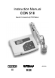
Instruction Manual CON 510 Bench Conductivity/TDS Meter 68X090820 Rev 2 01/04 Technology Made Easy ...
Preface This manual serves to explain the use of the CON 510 bench meter. It functions in two ways, firstly as a step by step guide to help you to operate the meter. Secondly, it serves as a handy reference guide. It is written to cover as many anticipated applications of the meter as possible. If there are doubts in the use of the meter, please do not hesitate to contact the nearest Authorized Distributor.
TABLE OF CONTENTS 1 INTRODUCTION 2 DISPLAY AND KEYPAD FUNCTIONS 1 2.1 2.2 Display Keypad 1 2 3 PREPARATION 3 3.1 3.2 3.3 3.4 Conductivity Electrode Information Connecting the probe to the meter Connecting the AC/DC Adapter Connecting the Electrode Holder 3 3 3 4 4 CALIBRATION 5 4.1 4.2 4.3 4.4 4.5 4.6 4.7 4.
Instruction Manual 1 CON 510 INTRODUCTION Thank you for selecting the CON510 bench meter. This meter is a microprocessor-based instrument that is designed to offer advanced yet user-friendly features for discerning users - ideal for laboratory and plant applications. It measures Conductivity, Total Dissolved Solids (TDS) and temperature (oC/oF). It incorporates large memory capacity of up to 50 data sets and user-customisable functions – all are accessible through the membrane tactile keypad.
Instruction Manual 2.2 CON 510 Keypad The splash-proof membrane tactile keypad allows easy key entry. Each button, when pressed, has a corresponding graphic icon or indicator displayed on LCD. Some buttons have several functions depending on its mode of operation. Key Function ON/OFF Powers on and shuts off the meter. When you switch on the meter, the meter starts up in the mode that you last switched off from.
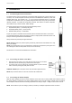
Instruction Manual 3 3.1 CON 510 PREPARATION Conductivity Electrode Information The CON510 bench meter is supplied with a Conductivity/TDS electrode (with a sturdy locking 6-pin connector). This Conductivity/TDS electrode (Code No: ECCONSEN91W/ 35608-50) comes with Stainless Steel rings, cell constant of K = 1.0, and a built-in temperature sensor for Automatic Temperature Compensation (ATC). Its specially designed Ultem-body housing has good chemicalresistant properties.
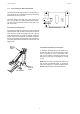
Instruction Manual 3.4 CON 510 Connecting the Electrode Holder The integral electrode holder serves as a handy holder for a few electrodes or a separate temperature probe during measurement or when not in use. This bench meter’s base plate has a side metal bar to which you can attach an integral swivel electrode holder. You can mount the electrode holder on either right or left side of the meter. To position the electrode arm: Use a Phillips screwdriver to remove the screw holding the electrode holder.
Instruction Manual 4 CON 510 CALIBRATION 4.1 Important Information on Meter Calibration The CON 510 bench meter allows you to perform automatic calibration (only for Conductivity mode) or manual calibration (applicable to both Conductivity/TDS mode). The meter can calibrate either single point or multi-point up to 5 calibration points (manual mode) with a maximum of 1 point in each measurement range.
Instruction Manual CON 510 Normalization Temperature: The factory default value for normalization temperature is 25 °C. If you need to normalize to a value other than 25 °C, see SETUP sub-menu P4.2. 4.2 Preparing the Meter for Calibration Before starting calibration, make sure you are in the correct measurement mode. Otherwise press MODE key to toggle between measurement modes. When you switch on the meter, it starts up in the last unit of measure when you last shut off the meter.
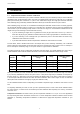
Instruction Manual 4.6 CON 510 Automatic Calibration (Only for Conductivity) In the automatic calibration mode, the CON 510 bench meter is capable of accepting either single-point or up to 4 points for multi-point calibration with maximum of 1 point per specific measurement range using known calibration standards values which include: 84 µS/cm (0 – 200.0 µS/cm), 1413 µS/cm (0 – 2000 µS/cm), 12.88 mS/cm (0 – 20.00 mS/cm) and 111.8 mS/cm (0 – 200.0 mS/cm). NOTE: You need to set your desired option i.e.
Instruction Manual 4.7 CON 510 Manual Calibration (Conductivity/TDS) The meter accepts either single point or multi-point (up to 5 points) manual calibration with maximum of 1 point per measurement range. Freshly prepare your standards solution before calibration. Refer to the table in Section 4.1 for more details of the recommended standards calibration range. MODE MEAS READY uS . You can offset or manually adjust the Conductivity or TDS reading up to ±40% from its default setting.
Instruction Manual 4.8 CON 510 Temperature Calibration The Conductivity electrode (EC-CONSEN91W/ 35608-50) has a built-in temperature sensor for ATC. The temperature sensor is factory calibrated to the meter. Calibrate your sensor only if you suspect temperature errors that may have occurred over a long period of time or if you have a replacement probe. Temperature Calibration 1. Make sure the electrode is attached to the 6-pin connector. 2. Power the meter on.
Instruction Manual 5 CON 510 MEASUREMENT The CON 510 bench meter measures up to 5 different measurement ranges with auto-ranging capability which automatically detects and promptly switches to the appropriate range. The meter also allows measurements to be taken with automatic or manual temperature compensation. The factory default is ATC on. ATC basically compensates for any temperature variances of measured sample solution temperature automatically from the normalization temperature set.
Instruction Manual 5.2 CON 510 Manual Temperature Compensation NOTE: For manual temperature compensation, you must deactivate the ATC mode to ‘nO’ as shown in SETUP submenu P3.3. 5.2.1 Setting a manual temperature compensation value To set manual temperature compensation value, you need to determine and enter the desired temperature value into the meter. This value is based on which reading will be manually temperature compensated. You may select any temperature between 0 and 100 °C (32 to 212 °F).
Instruction Manual 5.4 CON 510 Using Manual Ranging Function Although the CON 510 bench meter has an automatic ranging capability, you may also manually select any specific measurement range you wish to work on by pressing RANGE each time for every range. ENTER RANGE MEAS READY Range Indicator Conductivity Range uS TDS Range (if TDS factor is 0.5) r1 0 – 20.00 µS/cm 0 – 10.00 ppm r2 0 – 200.0 µS/cm 0 – 100.0 ppm r3 0 – 2000 µS/cm 0 – 1000 ppm r4 0 – 20.00 mS/cm 0 – 10.
Instruction Manual 6 6.1 CON 510 MEMORY AND DATA INPUT FUNCTIONS Memory Input The meter’s non-volatile memory can store and recall up to 50 data sets which include Conductivity and temperature or TDS and temperature. Data sets are retained even if the power is shut off unless these stored data sets are being overwritten by new ones. MEAS READY uS . To store a reading: 1. During any measurement mode press MI/▲ key to input any data into the memory. 2.
Instruction Manual 7 CON 510 SETUP FUNCTIONS The setup mode allows you to customize the meter’s setting to your individual preferences. The CON510 meter features different main program menus and sub-menus which organize individual parameters like a matrix-format. Details of each main program menu: 1. P1.0: Viewing previous calibration data - all calibrated solutions for each range 2. P2.0: Viewing electrode diagnosis - effective cell constants for each range 3. P3.
Instruction Manual CON 510 SETUP . P5.0: Mode of Calibration Selection of Automatic or Manual Calibration (only in Conductivity mode) Selection of Single or Multi-point Calibration P6.0: Selecting cell constant Selecting cell constant K: 0.1, 1.0, 10.0 SETUP . P7.0: Reset to factory defaults Reset meter to factory defaults SETUP . 7.2 SETUP P1.0: Viewing Calibration Data CAL This mode lets you recall previous calibration data of Conductivity/TDS.
Instruction Manual 7.3 CON 510 P2.0: Viewing Electrode Diagnosis Main program 2.0 shows the effective cell constant for each range being calibrated. The cell constant is adjusted according to your calibration options that let you check the probe’s parameters for diagnostic purposes. 1. 2. 3. 4. From measurement mode, press SETUP key to enter into setup [SETUP] mode. Use MI/▲ or MR/▼ key to scroll through sub-menus until you view main-menu ELE P2.0 on the display.
Instruction Manual CON 510 P3.2 Selecting °C or °F You can select between °C and °F as unit of measure for temperature readings. Meter default is °C. ENTER RANGE SETUP 1. 2. 3. 4. From measurement mode, press SETUP key to enter into Setup [SETUP] mode. Use MI/▲ or MR/▼ key to scroll through the SETUP main-menu P3.0 and press ENTER until you can view sub-menu P3.2 on the display. Use MI/▲ or MR/▼ key to toggle between °C and °F.
Instruction Manual CON 510 P3.4 Setting the TDS factor (In TDS Mode) The concentration of salts dissolved in solution increases the conductivity of that solution. This relationship varies from salt to salt and is roughly linear over a given range for a given salt. The TDS conversion factor is the number used by the meter to convert from conductivity to TDS.
Instruction Manual CON 510 P4.2 Adjusting the Normalization Temperature Your meter will normalize its conductivity measurements to a standard temperature that you can select. You can adjust the normalization temperature from 15 to 30 °C (59 to 86 °F). Meter default is 25.0 °C (77 °F). 1. 2. 3. 4. 5. From measurement mode, press SETUP to enter into setup [SETUP] mode. Use MI/▲ or MR/▼ key to scroll through the SETUP main-menu P4.0 and press ENTER thrice repeatedly until you can view the sub-menu P4.
Instruction Manual 7.6 CON 510 P5.0 Mode of calibration The CON 510 bench meter allows you to perform automatic (only for Conductivity mode) or manual calibration (applicable to both Conductivity/TDS mode). Similarly you may choose to perform either single-point or multi-point calibration (up to 4 preset calibration standards in automatic calibration mode). Refer to the Section 4 for details on calibration. 1. 2. 3. 4. 5. 6. From measurement mode, press SETUP to enter into setup [SETUP] mode.
Instruction Manual 7.7 CON 510 P6.0 Selecting the cell constant This program allows you to select the appropriate cell constant of K = 0.1, 1.0 or 10.0 which is suitable for measurement range being used. Use a cell of K = 1.0 for mid-range measurements Use a cell of K = 10 for high range measurements (above 20 mS or 10 ppt). Use a cell of K = 0.1 for low range measurements (below 20 µS or 10 ppm). The cell included with your meter has a cell constant of K = 1.0. 1. 2. 3. 4.
Instruction Manual 7.8 CON 510 P7.0: Resetting to factory default settings ENTER RANGE Program 7.0 allows you to reset all parameters to factory default settings. This clears all calibration data, memory, and any other setup functions you might have changed. IMPORTANT: Once activated the meter’s settings and calibration data will be erased and always exercise caution as meter reset is not reversible. 1. 2. 3. 4. From measurement mode, press SETUP key to enter into setup [SETUP] mode.
Instruction Manual 8 CON 510 PROBE CARE AND MAINTENANCE Keep the Conductivity/TDS probe clean. Rinse the probe twice, and gently swirl it while you take readings. For best accuracy, soak a dry probe for at least 5 to 10 minutes or longer before calibration. Rinse probe with deionized or tap water before storing. Never scratch the bands with a hard substance. Do not strike the probe against any hard surface. Do not immerse the probe in oily solutions.
Instruction Manual 9 CON 510 TROUBLE SHOOTING GUIDE Problem No display Unstable readings “Or” on upper display Not able to calibrate Possible Cause Solution A. AC outlet not switched on. A. Switch on power supply. B. AC adapter socket not inserted properly B. Re-insert AC adapter socket. A. Air bubbles in probe A. Tap probe to dislodge air bubbles. B. Dirty probe B. Clean probe and recalibrate. C. External noise pickup C. Move away from noise. D. Broken probe D. Replace probe. A.
Instruction Manual CON 510 11 SPECIFICATIONS SPECIFICATIONS Conductivity Range CON510 0 to 20.00, 200.0, 2000 µS/cm; 0 to 20.00, 200.0 mS/cm TDS Range 0 to 10.00, 100.0, 1000 ppm; 0 to 10.00, 100.0, 100 ppt (max. 200 ppt depending on factor setting) Resolution 0.05 % Full Scale Accuracy ±1% Full Scale 0.0 to 100.0 °C; 32.0 to 212 °F Temperature Range Temperature Resolution / Accuracy 0.1 ° / ± 0.5°C or ± 0.9°F Cell Constant 0.1, 1.0, 10.
Instruction Manual CON 510 12 ACCESSORIES Replacement Meter and Accessories Item Description Eutech Instruments Oakton Instruments Order Code No. Order Code No. CON 510 Bench Conductivity/TDS meter complete with conductivity/TDS electrode (EC-CONSEN91W/ 35608-50) and integral electrode stand EC-CON510/03S 35611-00 2-ring Stainless Steel, Ultem body Conductivity/TDS Electrode with built-in temperature sensor (for ATC), cell constant k = 1.
Instruction Manual CON 510 13 NOTE: CONDUCTIVITY AND TDS SOLUTIONS HAVE ±1 % ACCURACY AT 25°C ADDENDUM 1: CALIBRATION TIPS You only need one calibration for measurement throughout the entire range of the meter. If a range was not calibrated, the meter automatically detects the closest range calibrated and uses that calibration information. However, only the ranges that were calibrated have maximum accuracy.
Instruction Manual CON 510 15 ADDENDUM 3: CALCULATING TEMPERATURE COEFFICIENTS To determine the temperature coefficient of your sample solution use this formula: Where: tc = Temperature coefficient CT1 = Conductivity at Temp 1 T1 = Temp 1 25 = 25 °C CT2 = Conductivity at Temp 2 T2 = Temp 2 NOTE: A controlled temperature water bath is ideal for this procedure. 1. 2. 3.
Instruction Manual CON 510 16 ADDENDUM 4: METER FACTORY DEFAULT SETTINGS Type Default Remarks –– No calibration data for first range P1.2 –– No calibration data for second range P1.3 –– No calibration data for third range P1.4 –– No calibration data for fourth range P1.5 –– No calibration data for fifth range 1.000 No offset for effective cell constant (first range) P2.2 1.000 No offset for effective cell constant (second range) P2.3 1.
Instruction Manual CON 510 17 WARRANTY The CON 510 bench meter is supplied with a 3-year warranty from manufacturing defects and electrodes for 6 months from the date of purchase. If repair or adjustment is necessary and has not been the result of abuse or misuse within the designated period, please return – freight pre-paid – and correction will be made without charge. Eutech Instruments/ Oakton Instruments will determine if the product problem is due to deviations or customer misuse.
For more information on Eutech Instruments/ Oakton Instruments’ products, contact your nearest distributor or visit our website listed below: Oakton Instruments P.O Box 5136, Vernon Hills, IL60061, USA Tel: (1) 888-462-5866 Fax: (1) 847-247-2984 E-mail: info@4oakton.com Web-site: www.4oakton.com Eutech Instruments Pte Ltd Blk 55, Ayer Rajah Crescent, #04-16/24 Singapore 139949 Tel: (65) 6778 6876 Fax: (65) 6773 0836 E-mail: marketing@eutechinst.com Web-site: www.eutechinst.