Instruction Manual DO 100 Hand-held Dissolved Oxygen Meter 68X235201 Technology Made Easy ...
Preface This manual serves to explain the use of the DO 100 hand-held meter. It functions as a step by step guide to help you to operate the meter and as a handy reference guide. It is written to cover as many anticipated applications of the DO 100 meter as possible. If there are doubts in the use of this meter, please do not hesitate to contact the nearest Eutech Instruments/Oakton Instruments Authorised Distributor.
TABLE OF CONTENTS 1 INTRODUCTION 2 DISPLAY AND KEYPAD FUNCTIONS 2.1 2.2 3 3.1 3.2 3.3 4 4.1 4.2 4.3 5 5.1 Display Keypad Inserting the Batteries Connecting the Probe Connecting the AC Adapter Temperature Calibration DO Calibration in Air (with ATC) –% Saturation Mode DO Calibration in mg/L Mode Taking Measurement MEMORY FUNCTION 9 9.1 9.2 9.3 9.4 9.5 8 9 11 13 MEASUREMENT 7 8.1 8.2 5 5 6 7 CALIBRATION HOLD FUNCTION 8 2 2 3 PREPARATION 6 7.1 7.
Instruction Manual 1 DO 100 INTR ODUCTION Thank you for selecting the DO 100 portable meter. The DO 100 portable meter is a microprocessor-based instrument that is designed to be practical and user-friendly. It is capable of measuring Dissolved Oxygen (DO) in mg/L or ppm units, % saturation and temperature. This meter has many user-friendly features – all of which are completely accessible through the water-resistant membrane keypad.
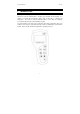
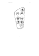
Instruction Manual 2 2.1 DO 100 D ISPLAY AND K EYPAD FU NCTION S Display The LCD has a primary and secondary display. • The primary display shows the measured DO value either in mg/L, ppm or %, depending on units of measurement selected. • The secondary display shows the temperature in °C. The display also shows error messages, keypad functions and program functions. See Figure 1.
Instruction Manual 2.2 DO 100 Keypad The large membrane keypad makes the instrument easy to use. Each button, when pressed, has a corresponding graphic indicator on the LCD. See Figure 2. Some buttons have several functions depending on its mode of operation. Key Function ON/OFF Powers on and shuts off the meter. When you switch on the meter, the meter starts up in the mode that you last switched off from.
Instruction Manual DO 100 Figure 2: Keypad 4
Instruction Manual 3 3.1 DO 100 PR EPARATION Inserting the Batteries The DO 100 is packaged with 4 “AAA” alkaline batteries required for operation. To insert the batteries into the meter, follow the procedure outlined below. 1. To open the battery compartment, press down the catch of the battery cover. See Figure 3a below. 2. Note the polarity and insert the batteries into the battery compartment correctly (Figure 3b). 3.
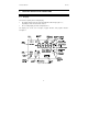
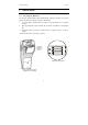
Instruction Manual 3.2 DO 100 Connecting the Probe The DO 100 uses a special notched 6-pin connector to attach the probe to the meter. NOTE: Do not substitute other probes or electrodes. For replacement probe, see the Section 14 “Accessories” on page 52. NOTE: Keep connector dry and clean. Do not touch connector with soiled hands. To connect the Dissolved Oxygen probe: 1. Line up the notch and 6 pins on the meter with the holes in the 6 pin connector.
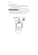
Instruction Manual 3.3 DO 100 Connecting the AC Adapter The AC adapter is not included with your meter; see the Section 14 “Accessories” on page 52. Ensure that the input mains voltage (110 or 220 V at 200 mA) matches your adapter requirements. 1. 2. Insert the AC jack as shown in Figure 5 below. Switch off the meter before plugging the adapter into the power source. This safety precaution protects the software in your meter. 3. Press the ON/OFF button to switch meter on.
Instruction Manual 4 DO 100 CA LIBRATION The amount of oxygen dissolved in water will depend on its temperature, atmospheric pressure and its salinity. While the pressure and salinity values are manually entered into the instrument, the temperature is being measured by the probe. It is therefore very important that the temperature is calibrated if necessary prior to the DO calibration. The measurements of % Saturation of DO will linearly affect the measurement for DO in mg/L.
Instruction Manual 4.1 DO 100 Temperature Calibration DO in mg/L is dependent on temperature, so it is first necessary to calibrate or verify the temperature reading. Temperature calibration is accessible from the mg/L or ppm measurement mode. This is illustrated in the flow diagram in Figure 7. The temperature sensor is part of the DO probe and the “ATC” annunciator will light up on the LCD screen once the probe is connected correctly to the meter. 1.
Instruction Manual DO 100 Figure 7: Flow Diagram for Temperature and mg/L (ppm) Calibration 10
Instruction Manual 4.2 DO 100 DO Calibration in Air (with ATC) –% Saturation Mode You can calibrate this meter quickly and easily in air. The exact calibration value depends on barometric pressure. The meter is set to a factory default of 760 mm Hg, which results in a calibration value of 100% saturation in air. NOTE: If the barometric pressure setting has been changed from 760 mm Hg, the calibration value in air will automatically adjust to a value other than 100%.
Instruction Manual DO 100 To calibrate 0% Saturation: SETUP MEAS READY SET % °C ATC OFF MEM Figure 9: Calibration for 0.0% Saturation 1. ENTER Power on the unit and immerse the DO probe in SETUP 0% solution. Ensure that the tip of the probe is completely immersed. Stir gently to create a homogenous solution. Wait for the reading to stabilise. It should be less than 10%. 2. Press SET key once to go to SETUP mode. The SETUP indicator will appear above the primary ENTER display. 3.
Instruction Manual 4.3 DO 100 DO Calibration in mg/L Mode As mentioned in the beginning of this section, the amount of oxygen dissolved in a liquid will depend on its temperature, pressure and salinity. It is therefore very important to set these parameters correctly before attempting to do a calibration. Temperature is measured by the meter automatically. Therefore it is important to do a Temperature Calibration (as described in Section 4.1) before attempting DO calibration.
Instruction Manual 5 DO 100 M EA SUR EM EN T During measurement, care must be taken not to allow the membrane of the DO probe touch any surface. It is always advisable to insert the probe guard (refer to Figure 33 and 34 on pages 40 and 41). The probe can either be fully or partially immersed in the solution. The READY indicator appears on the display when the readings stabilise. It will turn off if the readings start to fluctuate.
Instruction Manual 6 DO 100 HOLD FUNCTION This feature lets you freeze the value of the DO reading for a delayed observation. HOLD can be used any time when in MEAS mode. 1. To hold a measurement, press the HOLD key while in measurement mode. “HOLD” will appear on the display. See Figure 12. 2. To release the held value, press HOLD again. Continue to take measurements. NOTE: This meter shuts off automatically after 20 minutes of last key press.
Instruction Manual 7 DO 100 MEMORY FUNC TION The DO 100 can store up to 16 sets of data. Each data stored can either be in % Saturation, mg/L or ppm together with its respective temperature reading taken at that moment. Stored data can be easily recalled based on LIFO (Last-InFirst-Out) system. 7.1 Data Input To clear all data from memory, refer to Sections 8.1.1 (page 23) or 8.2.1 (page 31) on the procedure. 1. Switch on the meter by pressing ON/OFF key. 2.
Instruction Manual DO 100 Data No. MEM Symbol Data No. MEM Symbol 1 1 9 9 2 2 10 A 3 3 11 b 4 4 12 C 5 5 13 d 6 6 14 E 7 7 15 F 8 8 16 0 Since the memory management is based on LIFO, once memory is full, the first value that was stored in the memory will be erased to create space for the new value to be input. NOTE: Data input will remain even after the meter is switched off.
Instruction Manual 7.2 DO 100 Memory Recall Based on LIFO memory management, the last data input into memory will be recalled first. The data recalled will depend on which measurement mode (mg/L or % Saturation) the meter is presently in. For example, if the meter is in % Saturation measurement mode, pressing MR/ key will recall data recorded in that measurement mode only. NOTE: For the following illustration, please note data recorded Section 7.1, Data Input. 1. Ensure the meter is in MEAS mode.
Instruction Manual DO 100 To recall data input in the next measurement mode note the following procedure: 6. Press CAL/MEAS key to exit memory mode. 7. Press MODE key to toggle to the other measurement mode. 8. Press MR/ to recall data recorded in that measurement mode. 9. Press MR/ key again for next recorded data. See Figure 15. NOTE: To exit Memory mode, press CAL/MEAS key. The meter toggles back to measurement mode and is ready for measurement again.
Instruction Manual 8 DO 100 SET FUNCTION There are two setup parameters for each of the two measurement modes (% Saturation and mg/L or ppm). This is due to the different properties associated with each unit of measurement. The SETUP function is a powerful feature that allows you to customise the meter to your needs.
Instruction Manual 8.1 DO 100 SET Function in % Saturation Measurement Mode This part of the SETUP function allows display of values and the changing of parameters unique to the % Saturation measurement mode. Figure 16 on the following page shows the flow diagram of the SETUP menu. To access SETUP menu: 1. 2. Switch on the meter. Ensure that the measurement mode is in % Saturation. If not, press MODE key to change from mg/L or ppm measurement mode to % Saturation. 3. 4.
Instruction Manual 5. DO 100 Press ENTER and MI/ or MR/ key to enter the menu to change parameter or simply to view the value. At any level, press CAL/MEAS to exit setup function and go back to the measurement mode. Figure 16: Flow Diagram in SETUP Menu (% Saturation mode.
Instruction Manual 8.1.1 DO 100 P 1.0: Clr This clears all memory data input keyed during measurement. Default setting is OFF. 1. Press SET key to enter the first level in its setup menu. 2. 3. Press MI/ or MR/ key to switch to “ON”. Press ENTER key to confirm deleting all memory data. 4. The meter will pause briefly and move on to the next menu. See Figure 17.
Instruction Manual 8.1.2 DO 100 P 2.0: OFS This is a useful feature that allows you to offset meter’s value when cross referenced with another DO meter. That way, it can be standardised without you having to perform manual calculation. 1. Once you come to the setup menu shown in Figure 18, press ENTER. 2. 3. Dip the DO probe in a sample solution. Check the reading of another DO meter being used as a reference.
Instruction Manual 8.1.3 DO 100 P 2.2: bAr This menu allows you to do two things: • Select the appropriate unit of measurement of pressure --- either mm Hg or kPA. • Keying of actual atmospheric pressure value based on the altitude of the location. This is an important feature as DO is dependent on pressure (refer Section 12.1 on page 48).The DO 100 will use this input to compensate for the measured value automatically without having to refer to tables. 1.
Instruction Manual DO 100 Figure 19: Selecting Unit of Pressure & Adjusting its Value 26
Instruction Manual DO 100 REMARKS: The following 3 menus display the condition of the DO probe from the last calibration performed. Refer Figure 20 on the following page for flow diagram. 8.1.4 P 3.0: EL 1 This menu displays the slope of probe as a ratio of the ideal to the measured value. 1. Once you come to the [EL 1, P 3.0] menu shown in Figure 20, press ENTER. 2. The LCD will show the ratio value. Factor of 1 is the ideal value. 3. Press ENTER or HOLD key to go into the next menu. 8.1.5 P 3.
Instruction Manual DO 100 Figure 20: Checking Electrode Status in EL Menu 28
Instruction Manual 8.1.7 DO 100 P 4.1: rdY You can activate or deactivate the stabilising feature in the meter in this menu. 1. Once you come to the setup menu shown in Figure 21, press ENTER. 2. Press MI/ or MR/ key to toggle between ON or OFF. 3. Press ENTER or MODE key to go into the next menu. Figure 21: READY 8.1.8 P 4.2: A.oFF The meter has a Power Auto-off feature that switches off the unit 20 minutes after the last key press.
Instruction Manual 8.1.9 DO 100 P 5.0: r.Set This allows you to clear all parameters programmed above and re-set it to factory default values. 1. Once the [r.Set P 5.0] menu is reached (see Figure 23), press MI/ or MR/ key to turn reset feature ON (or OFF). 2. Press ENTER key to confirm selection. 3. The meter will clear all values and go back to measurement mode.
Instruction Manual 8.2 DO 100 SET Function in mg/L or ppm Measurement Mode This part of the SETUP function allows display of values and the changing of parameters unique to the mg/L measurement mode. Figure 25 on the following page shows the flow diagram of the SETUP menu. To access SETUP menu: 1. Switch on the meter. 2. Press MODE key to select mg/L. 3. Press SET key to enter the first level in its setup menu. 4.
Instruction Manual DO 100 Figure 25: Flow Diagram in SETUP Menu (mg/L or ppm) 32
Instruction Manual 8.2.2 DO 100 P 2.1: SAL This is a useful feature that allows you to key in the salinity value of the sample solution to be measured. 1. Once you come to the [SAL, P 2.1] menu shown in Figure 26, press ENTER. 2. Use MI/ or MR/ key to set the Salinity value in ppt of the liquid where DO is being measured. Salinity correction values from 0.0 to 50.0 ppt can be entered. 3. 4. Press ENTER key to confirm the value. The meter will accept the value and move on to the next menu.
Instruction Manual DO 100 NOTE: Press HOLD key to skip any part of the operation and move on to the next menu, or press CAL/MEAS key to exit setup menu to go back to measurement mode.
Instruction Manual DO 100 REMARKS: The following 2 menus display the condition of the DO probe from the last calibration performed. Refer Figure 28 for flow diagram. 8.2.4 P 3.0: EL 1 This menu displays the slope of probe as a ratio of ideal to its measured value. 1. Once you come to the [EL 1, P 3.0] menu shown in Figure 28, press ENTER. 2. The LCD will show the ratio value. Factor of 1 is its ideal value. 3. Press ENTER or HOLD key to go into the next menu. 8.2.5 P 3.
Instruction Manual 8.2.6 DO 100 P 4.0: do This menu allows you to choose between mg/L or ppm as unit of measurement. 1. 2. Press ENTER. Press MI/ or MR/ key to select “mg/L” or “ppm” as unit of measurement. 3. Press ENTER key to go into the next level. See Figure 29. Figure 29: Selecting mg/L or ppm as units of measure 8.2.7 P 4.1: rdY You can activate or deactivate the READY (rdY) stabilising feature in the meter in this menu. 1. Once you come to the [rdY, P 4.
Instruction Manual 8.2.8 DO 100 P 4.2: A.oFF The meter has a Power Auto-off feature that switches off the unit 20 minutes after the last key press. In situation where longer period of time is needed to take measurement, the power Autooff feature can be switched off in this menu. 1. Once the [A.oFF P 4.2] menu is reached (see Figure 31), press MI/ or MR/ key to turn Auto-off feature ON (or OFF). 2. Press ENTER key to confirm selection. 3. The meter will accept and move on to the next menu.
Instruction Manual 9 DO 100 DISSOLVED OXYG EN PROBE 9.1 Dissolved Oxygen Principle The probe is a galvanic measuring element which produces an output proportional to the oxygen present in the medium in which it is placed. The galvanic probe design lets you take measurements immediately – without the typical 15 minute wait of other dissolved oxygen probes. The probe consists of two parts: • An upper part consisting of an anode, a cathode, and cable.
Instruction Manual 9.2 DO 100 Probe Care Under typical operating conditions, the probe should last for several years. Proper care and maintenance will help you receive the maximum probe life and ensure more accurate readings. Since any deposits on the membrane surface act as a barrier to oxygen diffusing through the membrane, the membrane must be cleaned at regular intervals to assure maximum reliability.
Instruction Manual 9.3 DO 100 Membrane Housing Replacement Replacement of the membrane cap housing/ membrane is required only when you cannot calibrate the probe, or if the membrane is damaged. Typical membrane damages are punctures or wrinkles caused during measurements or cleaning. For more information see trouble-shooting guides in sections 9.6 and 10. Your new DO probe comes with a replacement membrane housing. To order more replacement membrane housing, see the “Accessories” section on page 52. 9.
Instruction Manual 9.4 DO 100 Membrane/O-ring Replacement (Optional Procedure) It is recommended only experienced service personnel can perform this procedure. This procedure is OPTIONAL, and should only be performed if you have new membrane and O-ring. You are also required to have a membrane installation tool. These items are available as optional accessories in the “Accessories” section. 1. Pull off the probe guard. See Figure 34. 2. Unscrew the membrane cap from the probe. 3.
Instruction Manual DO 100 10. Using the installation tool, screw the membrane lock back into the cap. Tighten the lock firmly over the membrane and O-ring, but do not over tighten. 11. Inspect the membrane for wrinkles. If wrinkles Installation tool Close Open exist, remove the membrane and repeat steps 8 – 11. 12. Fill the membrane cap with water and inspect the bottom for leaks.
Instruction Manual 9.5 DO 100 Electrolyte Solution The electrolyte solution in your probe’s cap will deplete on usage and will need to be replaced periodically. Your new DO probe comes with accessories of one 50-ml replacement electrolyte solution and a spare membrane cap. The replacement electrolyte comes premixed and ready to use. To order more electrolyte solution, see “Accessories” section.
Instruction Manual 9.6 DO 100 DO Probe Troubleshooting Table When experiencing difficulties with the equipment, keep in mind of the following: 1. Check for the obvious, such as physical condition of the probe, any signs of damage to the cable, power and signal connections etc. 2. Determine whether it is the probe, meter or the surrounding environment that is causing the problem. The following troubleshooting table identifies most of the problems likely to occur: Problem 1.
Instruction Manual Problem 3. It is not possible to calibrate the probe in air – the display will not read high enough after fully adjusting the offset. DO 100 Probable Causes Probe has dried out – no electrolyte inside. Probe is overdue for servicing – excessive build-up of anode oxide. A deposit has built-up on the silver cathode, which is inhibiting the reduction of oxygen at its surface. Solution Service probe and change membrane. Use a stiff nylon brush to remove the oxide built-up from the anode.
Instruction Manual DO 100 10 TR OUBLESHOOTING Problem No display when turned on Cause Solution Batteries not in place Check that batteries are in place and making good contact. Batteries not in correct polarity (+ and -). Reinsert batteries with correct polarity. Weak batteries Replace batteries or attach optional AC adapter. Insufficient reference electrolyte in probe. Fill probe with reference electrolyte. Broken probe. Replace the probe.
Instruction Manual DO 100 11 ERROR MESSAGES LCD Display Indicates Cause Solution Err 1 (in primary display) Memory write error. Instrument too old (> 10 years). Hardware failure. Turn meter on and off again. If message persists, return unit*. Err. 2 (in primary display) Memory checksum error. Hardware failure. Turn meter on and off again. If message persists, return unit*. Err. 3 (in primary display) A/D converter error. Hardware error. Turn meter on and off again.
Instruction Manual DO 100 12 ADD ITIONAL IN FORMAT ION 12.1 12.1.1 Dissolved Oxygen General Information Dissolved Oxygen (DO) refers to the volume of oxygen that is contained in water. There are two main sources of DO in water: from atmosphere and photosynthesis. Waves and tumbling water mix air into the water where oxygen readily dissolves until saturation occurs. Oxygen is also produced by aquatic plants and algae as a by-product of photosynthesis.
Instruction Manual 12.1.2 DO 100 Measurement Units One measure of DO in water is parts per million (ppm) which is the number of oxygen molecules (O2) per million total molecules in a sample. Calculating the % Saturation is another way to analyze DO levels. % Saturation is the measured DO level divided by the greatest amount of oxygen that the water could hold under various temperature and atmospheric pressure conditions multiplied by 100. 12.1.
Instruction Manual 12.1.4 DO 100 Air Calibration Understanding the principle of air calibration is easy, once you know that it is partial pressure that the probe is responding to. When the probe is in air, it is measuring the partial pressure of oxygen in air. If water is air saturated, then the partial pressure of oxygen in the water will be the same as it is in air. Therefore, all you need to know is the temperature of the air in which the probe is placed.
Instruction Manual DO 100 1 3 S P E C I F ICAT ION S Dissolved Oxygen Range Resolution Relative accuracy % Saturation of Oxygen Range Resolution Relative accuracy Temperature Range Resolution Relative accuracy Salinity Correction Range Resolution Method Barometric Pressure Correction (mm Hg) Range Resolution Method Probe Response Time No.
Instruction Manual DO 100 14 ACCESSORIES Replacements and accessories Eutech Instruments Item Eutech Instruments Ordering Code DO 100 Hand-held Dissolved Oxygen Meter complete with one Submersible Dissolved Oxygen probe with 3-meter (10-ft) cable (EC-DOHANDYNEW), one assembled membrane cap housing (15X241402) and one 50ml electrolyte (01X211226). EC-DO100/01 Submersible Dissolved Oxygen probe with 3-meter (10-ft) cable.
Instruction Manual DO 100 Oakton Instruments Item Oakton Instruments Ordering Code DO 100 Hand-held Dissolved Oxygen Meter complete with one Submersible Dissolved Oxygen probe with 3-meter (10-ft) cable (EC-DOHANDYNEW), one assembled membrane cap housing (15X241402) and one 50ml electrolyte (01X211226). 35640-00 Replacement submersible Dissolved Oxygen probe with 3-meter (10-ft) cable.
Instruction Manual DO 100 15 WARRANTY This meter is supplied with a three -year warranty, six-month warranty for probe against significant deviations in material and workmanship. If repair or adjustment is necessary and has not been the result of abuse or misuse within the designated period, please return – freight pre-paid – and correction will be made without charge. Eutech Instruments/ Oakton Instruments will determine if the product problem is due to deviations or customer misuse.
For more information on Eutech Instruments/ Oakton Instruments’ products, contact your nearest distributor or visit our website listed below: Oakton Instruments P.O Box 5136, Vernon Hills, IL 60061, USA Tel: (1) 888-462-5866 Fax: (1) 847-247-2984 E-mail: info@4oakton.com Web-sites: www.4oakton.com www.oaktoninstruments.com Eutech Instruments Pte Ltd. Blk 55, Ayer Rajah Crescent, #04-16/24 Singapore 139949 Tel: (65) 6778 6876 Fax: (65) 6773 0836 E-mail: marketing@eutechinst.com Web-site: www.eutechinst.