Instruction Manual Cond 6+ Conductivity/Temp TDS 6+ TDS/Temp Salt 6+ Salinity/Temp 68X243635 Technology Made Easy ...
Preface This manual serves to explain the use of the Conductivity, TDS, and Salinity handheld meters. The models covered are the CON 6+, TDS 6+, and Salt 6+. This manual functions in two ways: first as a step by step guide to help you operate the meter; second, it serves as a handy reference guide. This manual is written to cover as many anticipated applications of the Conductivity, TDS, and Salinity handheld meters as possible.
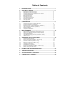
Table of Contents 1. INTRODUCTION........................................................................1 2. GETTING STARTED..................................................................2 2.1 2.2 2.3 2.4 2.5 2.6 2.7 2.8 2.9 Description of Keypad Functions .................................................................2 Description of LCD Annunciators.................................................................3 Inserting & Removing the Rubber Armour / Stand...................................
10. CALIBRATION TIPS..................................................................29 11. CALCULATING TDS CONVERSION FACTOR ........................30 12. CALCULATING TEMPERATURE COEFFICIENTS ..................31 13. REPLACEMENTS AND ACCESSORIES ..................................32 14. WARRANTY ..............................................................................33 15. RETURN OF ITEMS ..................................................................
Instruction Manual COND 6+, TDS 6+, SALT 6+ 1. INTRODUCTION Thank you for purchasing the COND 6+, TDS 6+, or SALT 6+ meter. These microprocessor-based handheld meters are economical and easy to use. It has a large custom LCD (Liquid Crystal Display) for clear and easy reading. The Cond 6+ measures conductivity (µS/cm or mS/cm) and temperature (°C) while the TDS 6+ measures total dissolved solids (TDS) in parts per million (ppm) or parts per thousand (ppt) and temperature (°C).
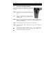
Instruction Manual COND 6+, TDS 6+, SALT 6+ 2. GETTING STARTED 2.1 Description of Keypad Functions Your meter has 6 keys on its splash-proof keypad. Some buttons have multiple functions depending on the mode of operation. ON/OFF Powers meter on and off. Meter starts up in the measurement mode that you last switched off from. CAL Enters into calibration mode. Pressing while in calibration mode will abort calibration without confirming value. MODE Selects desired measurement mode.
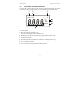
Instruction Manual 2.2 COND 6+, TDS 6+, SALT 6+ Description of LCD Annunciators Your meter has a large custom LCD that consists of 4-digit segments plus annunciators for uS/mS (Cond 6+), ppm/ppt (TDS 6+), or ppt/% (Salt 6+) and °C (temperature). 7 5 6 % HO LO °C m µS pptm 4 3 2 1 1. Primary display 2. Parts per million (ppm) (TDS 6+ only). Parts per thousand (ppt) (TDS 6+ & Salt 6+ only). 3. Milli-Siemens/cm (mS) or micro-Siemens/cm (µS) indicator (Cond 6+ only). 4. Temperature indicator. 5.
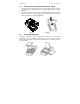
Instruction Manual 2.3 COND 6+, TDS 6+, SALT 6+ Inserting & Removing the Rubber Armour / Stand 1. To remove meter from rubber armour, push out from the bottom edges of meter until it is completely out of boot. Ensure that your electrode cables are not connected. Figure A. 2. To insert meter into armour, slide in from the top of meter before pushing the bottom edges of meter down to set it into position. Lift up the stand at the back of meter for bench top applications if necessary. Figure B.
Instruction Manual 2.5 COND 6+, TDS 6+, SALT 6+ Battery Replacement A “LO” annunciator in the LCD alerts you when battery power is running low. See below. LO µS "LO" Battery Condition Caution: Power off the meter when changing battery. 2.6 Electrode Information Your meter includes an electrode with a BNC connector (ECCONSEN91B) having a nominal cell constant of k = 1.0, and a built-in temperature sensor. The Ultem-body housing has good chemical resistant properties.
Instruction Manual COND 6+, TDS 6+, SALT 6+ 1. DO NOT measure or calibrate without the protective probe guard in place. 2. Immersion above the protective guard is not recommended. The cable can be submerged briefly but is not designed for continuous immersion. See “Probe Care and Maintenance” for more information. 2.7 Connecting the Electrode 1. To connect electrode, align the connector slots with the posts of meter’s socket and rotate connector clockwise until it locks. 2.
Instruction Manual 2.8 COND 6+, TDS 6+, SALT 6+ Switching the Meter On Press ON/OFF to power up your meter. Your meter will cycle through various setup parameters when switched on. 1. The first screen shows the model [Con6] [tdS6] [SAL6]. 2. The second screen shows the nominal cell constant value. The Cond 6+ and TDS 6+ meters can accept electrodes with k = 0.1, 1.0 or 10.0 nominal cell constants. The Salt 6+ can be used with 1.0 only. Default value is k = 1.0 [C 1.0]. See Section 5.
Instruction Manual COND 6+, TDS 6+, SALT 6+ TDS 6+ °C ON OFF pptm % HO LO MAX MIN pH % °C° F m µS pptmV ppm Measurement Mode Salt 6+ % °C ON OFF ppt JKT HO LO MAX MIN pH % % °C ° F m µS pptmV Measurement Mode (when probe is held in air) 2.9 Changing Mode To switch between conductivity/TDS/salinity measurement mode and temperature measurement mode, simply press the MODE key. The annunciator will indicate the measurement mode you are in.
Instruction Manual COND 6+, TDS 6+, SALT 6+ 3. CALIBRATION 3.1 Important Information on Meter Calibration The COND 6+ and TDS 6+ have five measuring ranges listed below. Each range can be calibrated to one point per range (five total points if each range is calibrated). Calibration is recommended for each range that will be utilized. The Salt 6+ meter uses a special algorithm for the measurement of sodium chloride concentration.
Instruction Manual 3.2 COND 6+, TDS 6+, SALT 6+ Preparing the Meter for Calibration For best results, select a standard value close to the sample value you are measuring. Alternatively, use a calibration solution value that is approximately 2/3 the full-scale value of the measurement range you plan to use. For example, in the 0 to 2000 µS/cm conductivity range, use a 1413 µS/cm solution for calibration. Use fresh calibration standard solutions.
Instruction Manual COND 6+, TDS 6+, SALT 6+ With manual calibration, you are not limited to the calibration standard values listed previously. Manual calibration is useful when you wish to use one or more standard values that are not listed above. See Section 5.3 Advanced Setup to modify automatic or manual calibration. 3.4 Using Automatic Calibration (COND 6+) In Automatic Calibration mode, the COND 6+ can accept up to 4 calibration points with maximum of 1 point per measurement range.
Instruction Manual COND 6+, TDS 6+, SALT 6+ NOTES: 1. To protect from erroneous calibrations, the allowable tolerance is ±40% of the factory default value. If calibration is attempted with standards that fall outside this tolerance range, the error message “Err 1” is indicated and meter will return to measurement mode. For example, a 40% tolerance of a 1413 µS/cm standard, is 848 µS/cm to 1978 µS/cm. 2.
Instruction Manual 3.5 COND 6+, TDS 6+, SALT 6+ Manual Calibration In Manual Calibration mode you are not limited to the conductivity calibration standards listed previously in Table 1. This example shows a manual calibration sequence using a 12.00 mS/cm conductivity calibration standard. 1. If necessary, press MODE key to select conductivity mode. 1. Rinse the probe thoroughly with de-ionized water or a rinse solution, then rinse with a small amount of calibration standard. 1.
Instruction Manual 3.6 COND 6+, TDS 6+, SALT 6+ Temperature Calibration The electrode includes a built-in temperature sensor that is factory calibrated with the meter. Perform temperature calibration only if you suspect temperature errors may have occurred over time or when the probe is replaced. °C CAL You can offset the temperature reading up to ±5 °C from the original (default) reading. 1. Connect the mini phono plug of the electrode to the meter. See Section 3.7. 2.
Instruction Manual COND 6+, TDS 6+, SALT 6+ 4. MEASUREMENT Your meter is capable of taking measurements that incorporate temperature measurements automatically (most common) or using a temperature which you input manually (rare). 4.1 With Automatic Temperature Compensation (ATC) To compensate your reading using temperature values as measured by your electrode, simply attach the phono plug of the electrode to the meter.
Instruction Manual 4.3 COND 6+, TDS 6+, SALT 6+ Taking Measurements 1. Rinse the electrode with de-ionized or distilled water before use to remove any impurities. Shake or air dry. To avoid contamination or sample dilution, rinse probe with a small volume of your sample. 2. Dip the probe into the sample. 3. Allow time for the reading to stabilize. Note the reading on the display. NOTE: The protective probe guard must be attached during measurement.
Instruction Manual COND 6+, TDS 6+, SALT 6+ Auto-ranging Manual ranging: 0 - 20.00 uS/cm µS mS Manual ranging: 0 - 200.0 mS/cm Manual ranging: 0 - 200.0 uS/cm µS µS mS µS Manual ranging: 0 - 20.00 mS/cm Manual ranging: 0 - 2000 uS/cm NOTE: If the value of the solution you are measuring is higher than the range selected [Or] (over range) will appear. Press ▲ to select a measurable range. The meter resets to Auto-ranging function once it is turned off.
Instruction Manual 4.5 COND 6+, TDS 6+, SALT 6+ HOLD Function For prolonged observation of a reading, press HOLD while in measurement mode to freeze the display. 4. 5. To hold a measurement, press HOLD while in measurement mode. [HO] will appear on the display. µS HOLD ENTER HO To release the held value, press the HOLD again. [HO] will disappear and measure is resumed. µS NOTE: This meter shuts off automatically after 20 minutes of the last key press.
Instruction Manual COND 6+, TDS 6+, SALT 6+ Entering Advanced Setup Mode Cell Constant. Select k = 0.1, 1.0, or 10.0. Default value is 1.0. (COND 6+, TDS 6+ only) Select Automatic Calibration. “Yes” for auto calibration and “No” for manual calibration. Default value is “Yes”. (COND 6+ only) % Adjust Temperature Coefficient from 0.0 to 3.0 % per °C. Default value is 2.1 % per °C. °C Normalization Temperature. Select “20 °C” or “25 °C”. Default value is 25 °C. Adjust TDS factor from 0.4 to 1.0.
Instruction Manual 5.2 COND 6+, TDS 6+, SALT 6+ Select Cell Constant (COND 6+, TDS 6+ only) Your meter includes a probe with a nominal cell constant (k) of 1.0. Use probes with k = 0.1 and 10 (sold separately) for improved performance in extreme samples. Use this setup function to change the cell constant if necessary. Meter default is 1.0 to match the included probe. k = 0.1 ideal for low measurements <20 µS/cm (<10 ppm). k = 1.
Instruction Manual 5.4 COND 6+, TDS 6+, SALT 6+ Setting the TDS Factor (TDS 6+ only) The concentration of salts dissolved in solution increases the conductivity. This relationship varies from salt to salt and is roughly linear over a given range for a given salt. The TDS conversion factor is the number used by the meter to convert from conductivity to TDS. The TDS conversion factor can be set from 0.4 to 1.0. Default value is 0.5. See Section 13 – Calculating TDS Conversion Factor . 10.
Instruction Manual 5.6 COND 6+, TDS 6+, SALT 6+ Normalization Temperature You can set the meter to normalize its measurements to a temperature of either 25 °C or 20 °C. Default value is 25 °C. °C 1. Enter advanced setup as described in Section 5.1. 2. Press ▲ or ▼ until [t.nr °C] appears. Press ENTER. 3. Press ▲ or ▼ to select [25.0 °C] or [20.0 °C]. 4. Press ENTER to select and return to the [t.nr °C] setup function. 5.
Instruction Manual 5.8 COND 6+, TDS 6+, SALT 6+ Restore Factory Default Values Use this function to reset all parameters to factory default settings. This clears all calibration data and any other setup functions you might have changed. IMPORTANT: Once activated the settings and calibration data will be erased and can not be undone. 1. Enter advanced setup as described in Section 5.1. 2. Press ▲ or ▼ key until [UrSt] appears. Press ENTER. 3. Press ▲ or ▼ to select [Yes] or [no]. 4.
Instruction Manual 7. COND 6+, TDS 6+, SALT 6+ TROUBLESHOOTING Problem Cause Solution No display Batteries are not installed, were improperly installed, or are too weak Install batteries with correct + / polarity.
Instruction Manual 8. COND 6+, TDS 6+, SALT 6+ SPECIFICATIONS / FEATURES COND 6+ TDS 6+ Conductivity Ranges (Resolution) 0 to 20.00 (0.01) µS/cm 20.0 to 200.0 (0.1) µS/cm 200 to 2000 (1) µS/cm 2.01 to 20.00 (0.01) mS/cm 20.1 to 200.0 (0.1) mS/cm TDS Ranges (Resolution) 0 to 10.00 (0.01) ppm 10.0 to 100.0 (0.1) ppm 100 to 1000 (1) ppm 1.01 to 20.00 (0.01) ppt 20.1 up to 200.0* (0.1) ppt *depending on TDS factor used SALT 6+ 3 3 Salinity % Resolution 0.10 to 5.00 % 0.
Instruction Manual COND 6+, TDS 6+, SALT 6+ FEATURES Auto-Buffer Recognition Yes (COND 6+) Hold Function Yes “HO” Low Battery Indicator Salinity Conversion Factor Auto Shut Off Yes “LO” Non-linear Compensation (SALT 6+) 20 minutes after last key operation Display Custom LCD 0 to 50 °C Operating Temperature Power Requirements (4) AAA alkaline batteries (included) Battery Life >100 hours Meter Dimensions / Weight 15.7 x 8.5 x 4.
Instruction Manual COND 6+, TDS 6+, SALT 6+ 9. CONDUCTIVITY THEORY Conductance is a quantity associated with the ability of primarily aqueous solutions to carry an electrical current, I, between two metallic electrodes when a voltage E is connected to them. Though water itself is a rather poor conductor of electricity, the presence of ions in the water increases its conductance considerably, the current being carried by the migration of the dissolved ions.
Instruction Manual COND 6+, TDS 6+, SALT 6+ Thus derives the term specific conductance or conductivity. The relationship between conductance and specific conductivity is: Specific Conductivity, S.C.
Instruction Manual COND 6+, TDS 6+, SALT 6+ Conductivity and Temperature Conductivity in aqueous solutions reflects the concentration, mobility, and charge of the ions in solution. The conductivity of a solution will increase with increasing temperature, as many phenomena influencing conductivity such as solution viscosity are affected by temperature. The relationship between conductivity and temperature is predictable and usually expressed as relative % change per degree centigrade.
Instruction Manual COND 6+, TDS 6+, SALT 6+ 11. CALCULATING TDS CONVERSION FACTOR You can calibrate your meter using TDS calibration standard solutions. The calibration standard only needs to give the TDS value at a standard temperature such as 25 °C.
Instruction Manual 12. COND 6+, TDS 6+, SALT 6+ CALCULATING TEMPERATURE COEFFICIENTS To determine the temperature coefficient of your sample solution use this formula: Where: tc = Temperature coefficient 25 = 25 °C CT1 = Conductivity at Temp 1 CT2 = Conductivity at Temp 2 T1 = Temp 1 T2 = Temp 2 NOTE: A controlled temperature water bath is ideal for this procedure. 1. 2. 3.
Instruction Manual 13. COND 6+, TDS 6+, SALT 6+ REPLACEMENTS AND ACCESSORIES Description COND 6+ meter with probe. COND 6+ kit. Meter and probe in hard carry case with bottles of 84 µS/cm, 1413 µS/cm, 12.88 mS/cm, and rinse. TDS 6+ meter only and probe. TDS 6+ kit. Meter and probe in hard carry case with bottles of 50 ppm, 300 ppm, 3000 ppm, and rinse. SALT 6+ meter only and probe. SALT 6+ kit. Meter and probe in hard carry case with bottles of 5 ppt, 25 ppt, 45 ppt, and rinse.
Instruction Manual COND 6+, TDS 6+, SALT 6+ 14. WARRANTY This meter is supplied with a warranty against significant deviations in material and workmanship for a period of THREE years from date of purchase whereas probe with a SIX-month warranty. If repair or adjustment is necessary and has not been the result of abuse or misuse within the designated period, please return – freight pre-paid – and correction will be made without charge.
For more information on Eutech Instruments products, contact your nearest distributor or visit our website listed below: Eutech Instruments Pte Ltd. Blk 55, Ayer Rajah Crescent, #04-16/24 Singapore 139949 Tel: (65) 6778 6876 Fax: (65) 6773 0836 E-mail: eutech@thermofisher.com Web-site: www.eutechinst.