
Specifications


Instruction Manual Alpha DO 500
5
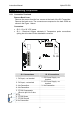
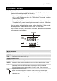
2.3 Connecting Peripherals
2.3.1 Connection Terminals
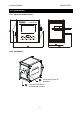
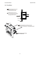
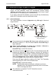
Remove Back Cover:
Remove the screws from the four corners at the back of the DO Transmitter.
Remove the back cover. The connectors are exposed on the back PCBA as
shown in the Figure 1 below.
Connectors:
x SL2 – 12 to 24 V DC power
x SL1 – Dissolved Oxygen electrode & Temperature probe connections
(wiring has to be done in the detachable connector
SL1
SL2
Figure 1: Outer Side of Back PCBA
SL1 Connections SL 2 Connections
1. DO Input, +ve terminal
1. DC Power Supply +ve
terminal
2. DO Input, -ve terminal
2. DC Power Supply –ve
terminal
3. No Connection 3. No Connection
4. No Connection
5. PT100 Compensate
(Short to pin 6 for 2-wire
RTD)
6. PT100 Sense
7. PT100 Ground
8. No Connection