
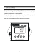
Specifications


2
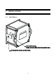
2 PREPARATION
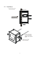
Remove screws from the four corners at the back of the Transmitter, and remove
back cover.
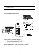
Connectors should be exposed as follows:
Figure 1 – Connection Guide
All wiring is done on 2 detachable connectors: –
1. 9-pin connector (located on SL1 position) for pH electrode, temperature
sensor and potential matching pin (PMP); &
2. 3-pin connector (located on SL2 position) for power supply.
Using a suitable screwdriver, loosen screws from top of connector.
When inserting the wires, always hold connector with top screws facing up.