Alpha pH 550 Monitor pH / ORP
R AQUAfast, Cahn, ionplus, KNIpHE, No Cal, ORION, perpHect, PerpHecT, PerpHecTion, pHISA, pHuture, Pure Water, Sage, Sensing the Future, SensorLink, ROSS, ROSS Ultra, Sure-Flow, Titrator PLUS and TURBO2 are registered trademarks of Thermo Fisher.
Preface This manual serves to explain the use of the Alpha pH 550 Monitor. The manual functions in two ways, firstly as a step by step guide to help the user operate the instrument. Secondly, it serves as a handy reference guide. This instruction manual is written to cover as many anticipated applications of the Alpha pH 550 Monitor. If you have doubts in the use of the instrument, please do not hesitate to contact your nearest Alpha Authorised Distributor.
TABLE OF CONTENTS 1 1.1 1.2 1.3 1.4 INTRODUCTION 1 Before You Begin ........................................................................................... 1 Intended Use.................................................................................................. 1 Safety Instructions.......................................................................................... 2 Taking Out of Service / Correct Disposal of the Unit ..................................... 2 2 2.1 2.2 2.3 2.4 2.
1 INTRODUCTION 1.1 Before You Begin Thank you for purchasing the Alpha pH 550 Monitor. The construction of the Alpha pH 550 Monitor employs leading edge technology and complies with safety regulations currently in force. Notwithstanding this, improper use could lead to hazards for the user or a third-party, and/or adverse effects on the plant or other equipment. Therefore, the operating instructions must be read and understood by the persons involved before working with the pH Monitor.
1.3 Safety Instructions 1.4 The Alpha pH 550 Monitor should be installed and operated only by personnel familiar with the instrument and who are qualified for such work. A defective pH Monitor must neither be installed nor put into service. The Alpha pH 550 must only be operated under the specified operating conditions (see section 6). The Alpha pH 550 must not be repaired by the customer. No modifications to the Alpha pH 550 are allowed.
2 2.1 GETTING STARTED Description of Instrument The Alpha pH 550 Monitor is used for measuring pH and temperature values. The pH values can be measured using industrial combination pH sensors. The temperature values can be measured using 3-wire Pt100 / Pt1000 sensors. The monitor can be used for applications such as water treatment and monitoring, galvanic-decontamination, chemical processing, food processing, clean or wastewater control and neutralization processes.
2.
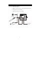
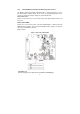
2.3 Connecting Peripherals 2.3.1 Connection Terminals Remove Back Cover: Remove the screws from the four corners at the back of the pH Monitor. Remove the back cover. The connectors are exposed on the back PCBA as shown in the Figure 1 below. Connectors: • J11 – 24V DC power • J8 – 9V DC power J10 - pH electrode & Temperature probe connections (wiring has to be done in the detachable connector J11 Connections 1. +ve 2. Gnd 24V DC J10 Connections 1. pH Sense 2. pH Reference 3. No Connection 4.
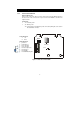
2.3.2 Switching Between PT100 & PT1000 Temperature Sensors The Monitor supports both Pt100 & Pt1000 (2-wire or 3-wire) temperature sensors. The default factory setting is Pt100. If you need to use Pt1000 temperature sensor, you have to change the jumper setting (J7) as described below. Remove Back Cover: Remove screws from the four corners at the back of the pH Controller. Remove the back cover. Remove Back PCBA: Remove the screw located center of the back PCBA (Figure 1).
2.3.3 Connecting pH/ORP Electrode 1. 2. If the pH/ORP electrode has a BNC connector, remove the BNC connector from the cable. NOTE: Oakton Instruments offers an optional ‘BNC to Spade Lug adapter’ (Order code: 05994-90) that can be used with pH/ORP electrode without removing the BNC connector. Strip the insulation of the cable so that the bare wires are exposed enough for connection as shown in Figure 3.
2.3.4 Connecting Temperature Probe For Automatic Temperature Compensated (ATC) pH readings, a 100Ω Pt RTD temperature probe (2-wire or 3-wire) can be connected to the Controller. 3-Wire Probe: 1. Connect PT100 compensate wire to Pin 5 of J10 connector 2. Connect PT100 sense wire to Pin 6 of J10 connector 3. Connect PT100 GND wire to Pin 7 of J10 connector 2-Wire Probe: 1. Short Pin 5 & 6 of J10 connector using a small piece of wire 2.3.5 2. Connect PT100 sense wire to Pin 6 of J10 connector 3.
2.4 2.4.1 Installation Mechanical Dimensions Alpha pH 550 Alpha pH 600 ESC CAL ENT pH Monitor PH/ORP RF Transmitter 2.4.
2.4.3 Panel Mount 1 Prepare panel cut-out of 92.0 mm X 92.
2.5 Display & Keypad 2.5.1 Display Overview The Liquid Crystal Display (LCD) of Alpha pH 550 has two alpha-numerical displays (Upper and a Lower). • Upper display: Measured pH, mV or relative mV value are displayed when the Monitor is in normal operation (measurement) mode. • Lower display: Measured temperature value is displayed when the Monitor is in normal operation (measurement) mode.
Mode Indicators MEAS Measurement mode; blinks in Symmetric mode (Refer Section 3.1& 5.5 ) SETUP Setup mode (Refer Section 5) CAL Calibration mode (Refer Section 4) Status Annunciators READY Appears when the reading is stable ATC Appears when Automatic Temperature Compensation (ATC) is enabled. Not visible when Manual Temperature Compensation (MTC) is enabled. Flashes if the temperature probe is faulty in its ATC mode. (Refer Section 5.3) ERR Appears when an error occurs (Eg.
2.5.2 Key Functions AlphapH pH600 550 Alpha ESC CAL ENT pHRF Monitor PH/ORP Transmitter Key Description CAL Enter Calibration mode. Enter Setup mode ENT Access sub screens (parameters) within a group of settings in Setup mode Confirm (save) setup parameters and numerical values Start/Confirm calibration in Calibration mode. Select a group of settings in Setup mode. Select parameters and increment/decrement numerical values in Setup and Calibration modes.
3 3.1 OPERATION Measurement mode When the pH Monitor is powered on, the display shows all the LCD segments briefly, and then automatically enters into the Measurement mode. MEAS pH READY 7.00 25.0 °C ATC The mode indicator ‘MEAS’ at the top of the display indicates that the pH monitor is in Measurement mode; ‘MEAS’ blinks when in Symmetric mode. The upper alphanumerical display shows the measured pH or mV value, while the lower display shows the temperature value.
3.2 Menu Overview 3.2.
4 4.1 CALIBRATION MODE Preparing the Monitor & Electrode for Calibration Before starting calibration, make sure that the pH Monitor is in appropriate measurement mode (pH or ORP). When the monitor is switched on, it starts up with the measurement mode last used. For example, if the pH Monitor is switched off in ORP measurement mode, it starts up in ORP mode when it is switched on. (Refer Section 5.
NOTES: 4.3 • To exit calibration mode at any time during calibration, press ▲ and ▼ keys simultaneously (escape). The pH Monitor returns to the measurement mode and the old calibration values remain active • The calibration is always carried out in the units of measurement (pH or mV), selected in setup mode pH Calibration The pH Monitor is capable of calibration of up to 2 points using USA or NIST pH buffer standards. All new calibration values will automatically override existing calibration data.
Upper display shows the current uncalibrated pH reading. Allow the reading to stabilize. LCD shows ‘READY’ annunciator when the reading is stable. Press CAL key to confirm the reading. The calibration is completed. The pH Monitor re-calculates electrode properties based on the calibration. The new slope (in mV) is shown in the upper display and pH reading at 0mV (pH7.00 ± offset) is shown in the lower display. Press ENT key to exit from the calibration. The pH Monitor reverts to pH measurement mode.
3 4 5 Press ENT key to confirm the reading. The pH Monitor moves to the second calibration point. The lower display shows next standard buffer value (pH 4.01). Use ▲ and ▼ keys to select your second buffer from one of the preset values: pH 4.01 or 1.68 or 10.01 or 12.45. Remove the electrode from the first buffer, rinse and then immerse it into the second buffer. Allow the reading to stabilize. LCD shows ‘READY’ annunciator when the reading is stable. Press ENT key (or CAL key) to confirm the reading.
1-Point Calibration: 3 2 1 CAL CAL ENT HOLD CAL pH READY HOLD 4 mV CAL MEAS ENT PH READY HOLD pH °C ATC pH From pH measurement mode press CAL key to enter calibration mode as described in section 4.2. The LCD shows ‘CAL PH’. Press ENT key to begin calibration. Place the electrode in pH 6.86 buffer. Immerse the temperature probe in the buffer solution if ATC mode is enabled. Immerse the potential matching pin 1 2 in the buffer if symmetrical mode is enabled.
1 2 3 4 5 From pH measurement mode press CAL key to enter calibration mode as described in section 4.2. The LCD shows ‘CAL PH’. Press ENT key to begin first calibration point. Place the electrode in pH 6.86 buffer. Immerse the temperature probe in the buffer solution if ATC mode is enabled. Immerse the potential matching pin in the buffer if symmetrical mode is enabled. The buffer annunciator appears in LCD. Lower display shows pH 6.86 (NIST standard buffer).
CAL ENT HOLD 3 2 1 CAL CAL mV READY HOLD 4 mV READY HOLD MEAS ENT R.mV READY °C ATC 1 2 3 4 4.5 From ORP measurement mode press CAL key to enter calibration mode as described in section 4.2. The LCD shows ‘CAL OrP’. Press ENT key to begin calibration. Place the electrode in a standard ORP solution of known OPR value. Immerse the temperature probe in the buffer solution if ATC mode is enabled. Immerse the potential matching pin in the buffer if symmetrical mode is enabled.
5 SETUP MODE 5.1 Enter Setup mode The setup mode allows you to customize the settings of the pH Monitor to suite your requirements. While in measurement mode, press the ENT key to access setup mode. LCD shows ‘SETUP’ mode indicator and the first page of setup (OFS – offset settings). Press ▲ or ▼ key to access other pages of the setup mode.
5.2 Electrode Offset Settings NOTE: ‘Electrode Offset Setting’ is not available when the pH Monitor is configured for ORP measurement mode. (Refer Section 5.5 for switching measurement modes) In applications where continuous pH measurement is required, it may not be convenient to remove the electrode for calibration. In such cases, an on-line offset adjustment is recommended. The pH Monitor allows you set an offset of up to ± 2.00pH to compensate for errors in the pH electrode.
allowed. Press ENT key to confirm the value. The pH Monitor reverts to OFS screen. Press ▲ or ▼ key to access other setup screens or press ▲ and ▼ key simultaneously (escape) to return to measurement mode. 5.3 Temperature Settings Automatic Temperature Compensation (ATC): The pH values other than pH 7.00 are affected by temperature. Use ATC feature of the pH Monitor to compensate for pH changes when the temperature of the sample or process liquid fluctuates.
2 3 Selecting unit of measurement for temperature: The upper display shows ‘Unit’ and the lower display shows the last configured unit of measurement for temperature. Press ▲ or ▼ key to select the desired units for temperature (ºC or ºF). Press ENT key to confirm your selection. Enable/disable ATC: The lower display shows ‘AtC’ and the upper display shows the last configured ATC selection (‘On’ or ‘OFF’). Press ▲ or ▼ key to enable (ATC On) or disable (ATC OFF) automatic temperature compensation.
Press ▲ or ▼ key to access other setup screens or press ▲ and ▼ key simultaneously (escape) to return to measurement mode. To exit from any intermediate steps, press ▲ and ▼ keys simultaneously (escape). The pH Monitor returns to the first screen of temperature settings SET ºCF. 5.4 Buffer Selection Settings NOTE: The buffer selection setting is only available if the monitor is configured for pH measurement mode.
Press ENT key to confirm your selection. The pH Monitor reverts to bUFF screen. Press ▲ or ▼ key to access other setup screens or press ▲ and ▼ key simultaneously (escape) to return to measurement mode. 5.5 Configuration Settings Configuration settings let you configure the pH Monitor to different measurement & operation modes & reset the pH Monitor to factory defaults.
1 SETUP ENT 4 3 2 SETUP SETUP ENT ENT 2 SETUP 4 3 SETUP SETUP SETUP ENT ENT ENT 4 SETUP ENT MEAS READY pH °C ATC 1 2 3 4 From pH (or ORP) measurement mode press ENT key to enter setup mode as described in section 5.1. The LCD shows the first screen of setup mode (OFS). Press ▲ or ▼ key to select configuration settings screen (Cnfg). Press ENT key to access configuration settings (Cnfg).
CAL dEF: Reset all calibration settings of the pH Monitor to factory defaults, when confirmed by pressing ENT key. Press ENT key to confirm your selection. - If ‘nO dEF’ was selected, the pH Monitor reverts to Cnfg screen. Press ▲ or ▼ key to access other setup screens or press ▲ and ▼ key simultaneously (escape) to return to measurement mode. - If ‘FCt dEF’ or ‘CAL dEF’ was selected, the pH Monitor performs the selected reset and returns to measurement mode.
1 2 From pH (or ORP) measurement mode press ENT key to enter setup mode as described in section 5.1. The LCD shows the first screen of setup mode (OFS). Press ▲ or ▼ key to select viewing electrode properties screen (CdAt). Press ENT key to view electrode properties (CdAt). Electrode status: The electrode annunciator appears in the LCD. For pH measurement mode, the slope (in mV) is shown in the upper display and pH reading at 0mV (pH7.00 ± offset) is shown in the lower display.
6 TECHNICAL SPECIFICATIONS General Specification (a) pH Measuring Range Resolution Accuracy 0.00 to 14.00 pH 0.01 pH ± 0.01 pH (b) mV Measuring Range Resolution Accuracy (c) Temperature Measuring range Resolution Relative accuracy Sensor Compensation -1000 to 1000 mV 1 mV ± 1 mV -10.0 to +125.0 oC or +14.0 to +257 oF 0.1 oC 0.1 oF (Resolution is 0.1 oF up to 199.9 oF and 1 oF for 200 oF and above) ±0.5 oC ±1.
7 LIST OF ACCESSORIES 7.
7.2 Eutech Instruments Order Code pH Monitor Replacement and Accessories Item Description Order Code Alpha pH 550 Monitor 56717-30 pH/Temp electrode with PMP and 10-ft cable 35807-20 Platinum ORP electrode with 10-ft cable 35801-21 BNC to spade lug adapter 05994-90 Calibration Solutions Item Description Order Code pH 4.01 calibration buffer, 500 ml 00654-00 pH 7.01 calibration buffer, 500 ml 00654-04 pH 10.01 calibration buffer, 500 ml 00654-08 pH 4.
8 TROUBLESHOOTING Problem Cause Solution Power on, but no display a) b) a) Unstable pH reading Loose connections Incorrect output voltage of the power adaptor a) b) b) Ensure cables make good contact Use an power adaptor with specified output voltage Oscillating temperature readings Slow response Dirty electrode Electrical noise interference a) Electrical noise interference a) Dirty / Oily electrode Clean electrode and recalibrate b) Switch to Symmetric mode a) Ensure shield wire is properly
9 9.1 GENERAL INFORMATION Warranty This monitor is supplied with a one-year warranty against significant deviations in material and workmanship from date of purchase and a six-month warranty for probe. Each instrument will have a warranty card with a specific serial number. The warranty card must be endorsed by the Authorized Distributor at the point of sale.
protection. Include a brief description of any faults suspected for the convenience of Customer Service Dept., if possible. 9.4 Maintenance and Cleaning Maintenance The Alpha pH 550 Monitor contains no user repairable components. Please contact your authorized distributor if there is any problem with the unit. Cleaning To remove dust, dirt and spots, the external surfaces of the pH Monitor may be wiped with a damp, lint-free cloth. A mild household cleaner can also be used if necessary.
10 APPENDICES 10.1 Appendix 1 – pH Buffer Values at Various Temperatures The following table shows the various pH values at different temperature of the solution during calibration. Temperature (oC) 0 5 10 15 20 25 30 35 40 45 50 55 60 70 80 90 pH 4.01 pH 6.86 pH 7.00 pH 9.18 pH 10.01 4.01 4.01 4.00 4.00 4.00 4.01 4.01 4.02 4.03 4.04 4.06 4.08 4.10 4.12 4.16 4.20 6.98 6.95 6.92 6.90 6.88 6.86 6.85 6.84 6.84 6.83 6.83 6.83 6.84 6.85 6.86 6.88 7.12 7.09 7.06 7.04 7.02 7.00 6.99 6.98 6.97 6.97 6.97 6.
CnFg Configuration dEF Default values FCt Factory (defaults) OFS Offset Or Reading is over range OrP Oxidation Reduction Potential P.
Water Analysis Instruments North America 166 Cummings Center Beverly, MA 01915 USA Toll Free: 1-800-225-1480 Tel: 1-978-232-6000 Dom. Fax: 1-978-232-6015 Int’l Fax: 978-232-6031 Europe P.O. Box 254, 3860 AG Nijkerk Wallerstraat 125K, 3862 CN Nijkerk, Netherlands Tel: (31) 033-2463887 Fax: (31) 033-2460832 Asia Pacific Blk 55, Ayer Rajah Crescent #04-16/24, Singapore 139949 Tel: 65-6778-6876 Fax: 65-6773-0836 www.thermo.com/process © 2009 Thermo Fisher Scientific Inc. All rights reserved.