
Instruction manual


- 5 -
2.3 Connecting Peripherals
2.3.1 Connection Terminals
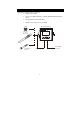
Remove Back Cover:
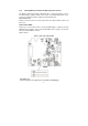
Remove the screws from the four corners at the back of the pH Monitor. Remove
the back cover. The connectors are exposed on the back PCBA as shown in the
Figure 1 below.
Connectors:
• J11 – 24V DC power
• J8 – 9V DC power
J10 - pH electrode & Temperature probe connections (wiring has to be done in
the detachable connector
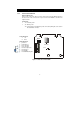
Figure 1: Outer Side of Back PCBA
24V DC
J1
J10
J8
9V DC Power
Screw
1)+v
e
J11 Connections
1. +ve
2. Gnd
J10 Connections
1. pH Sense
2. pH Reference
3. No Connection
4. No Connection
5. Pt 100 Compensate
6. Pt 100 Sense
7. Pt 100 GND
8. Potential Matching Pin