
Operation Manual
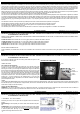
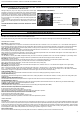

USING THE OVEN
The powers are set as follows:
P1, P2, P3, P4, P5, OVEN. Using the powers from P1 to P5 the stove works normally, as a classic stove, with predefined caloric power and room ventilation.
Pressing the 1 button you can change the Ambient Set. Using the OVEN mode the stove works according to the temperature of the oven. As you can see, inside
the oven there is a temperature probe which
controls the internal temperature. The caloric
power of the stove will be automatic:
depending on the temperature of the oven, it
will choose autonomously the power in order to
keep a constant temperature inside the oven.
The oven temperature can be set by pressing
the display key 1 only and exclusively in the
OVEN function. In case the oven temperature
exceeds the set temperature, the ambient
ventilation will bring at par the temperature
values.
TIMER
Once selected the TIMER OVEN mode, press
the (P2) power button and then the ON/OFF
button. At this point, it is proposed a timer in
minutes (default 60 minutes) that with the keys
(P1) and (P2) allows to change the time, which
can be confirmed with the ON/OFF button.
After the set time, the board's buzzer will beep
for 1 minute with a 2 beep-per-second
frequency.
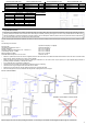
04.6 AIR STOVE
(Electronics p. 28)
IMPORTANT: THE LENGTH OF THE FLUE DUCT MUST BE OF MAX. 6 METERS WITH A DIAMETER OF 80 mm; EVERY 90° CURVE OR (T) CONNECTION
IS CONSIDERED AS 1 METER OF PIPE.
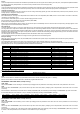
DUCTED STOVE FUTURA 15 KW AND FUTURA 19,5 KW
The 40 Kg pellet
hopper, remote
control, DFCS control
system for the
combustion air and
the air-tight system
renders it ideal for
passive houses, as it
does not take
combustion air from
the environment. It
can be fitted with
upper or rear
couplings for the ducts and it can be connected to an already existing thermostat or can be set to start when the room temperature reaches or use ambient probes
that regulate the ventilation speed and the relative power of the stove.
The fittings of the ducted air pipes have a diameter of 80 mm. For long distances, or if you need to pass through walls made of flammable material, we recommend
that you use insulated pipes. The insulation consists of a 50 mm thick insulating wall and therefore, the hole through wich the pipes will pass should have a diameter
of at least 140 mm. We recommend that you use gaskets so as to prevent any air leaks; the use of flexible tubes is not recommended as they might break during
the connection and also, the smooth ones are susceptible to pressure drops. However, you can install 100 mm diameter pipes.
The fume outlet can be located on the upper side or on the rear side of the stove.
You can decide between the rear and the top fume outlet based on the location of the vent pipe. If you opt for a rear fume outlet, you need to cut a piece of pipe
so as to determine the exact distance at which you have to make the connection to the curve that reaches the rear outlet.
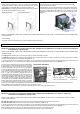
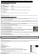
The air motor of room number 1, is the furthest to the left, as you look from the tank side.
The air motor of room number 4, is the furthest to the right.
Connect the 4 ducted air pipes as described above and then install the sensors or the
thermostats. You can connect 4 sensors (included in the supply) or 4 thermostats (not
included in the supply). You can connect the sensors or the thermostats using any 2-pole
cable with double insulation available on the market. The clamps on the back of the stove
are numbered and correspond to the numbers of the ducting outlets.
ATTENTION (limitations on installing sensors or thermostats):
• Room number 1 can be connected to a sensor but not to an actual thermostat:
the remote control will act as a thermostat. Therefore, if you want a thermostat in room
number 1, you will need to install the remote control system. However, install a sensor on input 1.
• If you install a thermostat in room 2, you must install one in room 3 too.
• If you install the sensor in room 2 you can freely install the thermostat in room 3.
Below you will find a table reporting the available configurations for the installation of thermostats or sensors:
Possible configurations
ROOM 1
Sensor / remote control Sensor / remote control Sensor / remote control Sensor / remote control Sensor / remote control Sensor / remote control
ROOM
2
Sensor
Sensor
Thermostat
Sensor
Sensor
Thermostat
ROOM 3
Sensor
Thermostat
Thermostat
Sensor
Thermostat
Thermostat
ROOM 4
Sensor
Sensor
Sensor
Thermostat
Thermostat
Thermostat
If you want to install thermostats you also have to contact the qualified technician who will change the settings of the parameters.
ATTENTION (limitations concerning the ventilation):
• As you will see in the following pages of this manual, the settings made on blower 3 are identical with those made on blower 4: by changing the setting on
blower 3 you will automatically change the settings of blower 4.
PAY UTMOST ATTENTION WHEN CHOOSING THE ROOMS AND TAKE INTO CONSIDERATION THE SENSOR/THERMOSTAT LIMITATIONS, MAKING
SURE THAT THE SPEED SETTINGS ON BLOWERS 3 AND 4 ARE THE SAME.
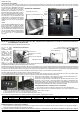
ON/OFF SWITCH
THERMOSTATS or EXTERNAL
SENSORS
REMOTE CONTROL RECEIVER
EMERGENCY SWITCH
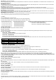
DESCRIPTION COMPONENTS
PELLET HOPPER LID
PELLET HOPPER LID GASKET
SAFETY THERMOSTAT
DOOR
PELLET
DROWER
HANDLE
DISPLAY
DOOR
HANDLE
VENTILATED AIR OUTLET
STEEL or GLASS CERAMIC PLATE
DESCRIPTION COMPONENTS
14