
Operation Manual


AL6 NO PELLET - No pellet alarm
The alarm is triggered when fume temperature falls below the value set by Pr13 parameter with stove in working mode. The message “AL6 NO PELLET " scrolls
on the display and the stove goes into the alarm status.
AL7 SAFETY THERMAL - Thermal safety overheating alarm
The alarm is triggered whenever the general safety thermostat detects a temperature exceeding the trigger threshold. The thermostat switches off the Auger tube,
being connected in series to its power supply, the control board reports the alarm status (alarm LED on) by showing the message “AL7 SAFETY THERMAL” on
the display and the stove switches off.
AL8 FAILURE DEPRESS - No negative pressure alarm
The alarm is triggered whenever the external pressure switch detects a pressure higher value below the trigger threshold. The pressure switch switches off the
Auger tube, being connected in series to each other, and the control board reports the alarm status (alarm LED on) by showing the message “AL8 FAILURE
DEPRESS” on the display. The stove switches off.
05.4 ELECTRONICS WITH 6 BUTTON LED DISPLAY N. 100 p. 3 F-1
(Pellet stoves – Pellet inserts)
PROPER FUNCTIONING AND CONTROL ADJUSTMENT DEVICES
Console
The control board can be managed by simply pressing a few buttons on the control panel. A display and the LED indicators inform about the stove operational
status. When in programming mode all the parameters that can be modified using the buttons are shown on the display.
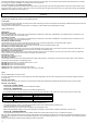
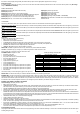
DESCRIPTION OF PANEL
Button (P1) Room temperature increase
Button (P2) Room temperature decrease
Button (P3) Set / menu
Button (P4) ON / OFF
Button (P5) Heat output decrease
Button (P6) Heat output increase
Display (D1):
It displays the detected room temperate and the time at start-up.
During working mode, it shows the heat output set by the user.
When modifying user/technician parameters, it shows the value of the
parameter in question.
MENU
Press P3 button to access the menu. It includes several items and levels to access settings and control board programming.
Menu M1 – SET CLOCK
Press the SET button (P3) once, i twill appear the menu M1 SET CLOCK, confirm by pressing SET (P3) once; with the arrows on the left SET(P3) the current day
and press SET (P3); SET (P3) the current time and press SET (P3); SET (P3) the minutes and then push SET (P3); SET (P3) the current day in numeber and
press SET (P3); SET (P3) the current month in number and press SET (P3); SET (P3) the current year in number, and at this point to confirm and exit the menu
M1 press once the power button.
Menu M2 – SET CHRONO
Submenu M2 - 1 CHRONO ENABLE
Press once the SET (P3) button and with arrow (P5) go to M2, enter the menu by pressing once SET (P3) so it appears the menu M2-1, confirm with SET
(P3) and with arrow (P1) put ON to activate the general chrono. To go back please press the button ON-OFF (P4), and with arrow (P5) select the program to
be activated.
Submenu M2 - 2 PROGRAM DAY
Two ON-OFF (P4) cycles fixed for each day.
Submenu M2 - 3 PROGRAM UEKK
Four ON-OFF (P4) cycles and every time must de selected daily.
Submenu M2 - 4 PROGRAM U-END
Two ON-OFF (P4) cycles for Saturday and Sunday.
To set a program:
Enter the desired program by pressing the SET (P3) button once and the first parameter is the enabling, put it in ON by pressing the arrow (P1) (ATTENTION:
ENABLE ONE PROGRAM AT A TIME TO AVOID PROBLEM). Press SET (P3) to SET (P3) the startʼs hour, with arrows (P1) and (P2) SET (P3) the hour of the
ignition and press SET (P3) to SET (P3) the stop hour. With arrows (P1) and (P2) SET (P3) the hour of the off. Then only in the weekly program this point you must
confirm by pressing SET (P3) the days, with arrows (P5) and (P6) move between the days of the week and with arrow (P1) put ON or OFF. When you SET (P3)
the times and days to confirm and exit the chrono press the ON-OFF (P4) button up to the home screen, if you have set the times correctly i twill light the green
LED, which is close to an hourglass in the left part of the upper display.
Menu M3 – LANGUAGE
Use this function to select one of the languages available. Press P1 (increase) and P2 (decrease) buttons to scroll through the options and press P4 button to
confirm.
Menu M4 – STAND-BY
Use it to enable or disable the Stand-by mode. Press P3 button to select menu M4 and then P1 or P2 to select the ON or OFF status. Refer to the section
concerning the stand-by mode for more details on its functioning.
Menu M5 – LOAD INITIAL
This function is only available when the stove is switched OFF. It allows the auger tube to be loaded upon the first stove start-up when the pellet hopper is empty.
After selecting menu M5, the message “P1 TO LOAD” will scroll on the display. Then press P1 (increase). The exhaust blower switches on at the maximum speed
and the auger tube (auger tube LED on) starts working. They will switch off once the period of time indicated on the display has elapsed or after pressing P4
button.
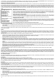
Menu M6 – STATE STOVE
After entering menu M6 by pressing P3 button, the status of a few parameters with stove in working mode scrolls on the display. The table below contains an
example of the values scrolling on the display together with their meaning.
Displayed status - meaning
3.1” - Auger tube pellet feeding status 52ʼ - Time out Toff - Thermostat status 106° - Fume temperature 1490 - Exhaust blower speed
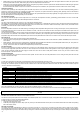
Led (L1) Chrono enabled - CHRONO
Led (L2) Auger tube moving – AUGER TUBE ON
Led (L3) Remote control receiver - REMOTE CONTROL
Led (L4) Thermostat on – ROOM TEMP SETTING
Led (L5) Flashing during temperature setup or when inside menus - SET
Display (D2):
It shows the board status during start-up phase.
During working mode, it shows the temperature set by the user.
When modifying user/technician parameters, it shows the label of the
parameter in question.
22