EN BusinessLine manual 1
EN Meet BusinessLine! Let’s get started.
EN BusinessLine manual
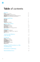
EN Table of contents General Errors or inaccuracies Communication regulations (FCC) Americans with Disabilities Act (ADA) compliance Product and environmental characteristics Safety regulations Warnings Cautions Remarks Transport and storage Product description Meet BusinessLine Components & features Networking your station BusinessLine Smart Charging features Operation 7 7 7 8 8 9 9 10 11 11 Charging with a QR code Charging with an RFID card or a key fob LED ring chart 12 12 12 13 Technical speci
EN General Errors or inaccuracies For any inaccuracies or omissions, or to provide feedback and suggestions, send an email to help@evbox.com. Communication regulations (FCC) This device complies with Part 15 of the FCC rules. Operation is subject to the following two conditions: (1) This device may not cause harmful interference and (2) this device must accept any interference received, including interference that may cause undesired operation.
EN Americans with Disabilities Act (ADA) compliance While single-family residential installations do not have complex parking requirements, commercial, public, and multi-unit residential installation have additional parking considerations that include Americans with Disabilities Act (ADA) accessible Electric Vehicle Charging Station (EVCS) spaces and meeting the minimum requirements for spaces in parking lots and facilities.
EN Safety regulations Warning: risk of electric shock • Please read the documentation provided with the charging station to familiarize yourself with the safety regulations before you use the charging station. • In the event of danger and/or accidents, have the charging station disconnected immediately by an electrician or facility manager. • Do not operate the charging station if it, or the charging cable, is physically cracked, frayed, or otherwise visibly damaged.
EN • Persons unable to assess the dangers involved in operating a charging station should not use the charging station. • Do not allow children to operate this device. Adult supervision is required when children are in the proximity of a charging station in use. • Make sure the charge cable is positioned so it will not be stepped on, driven over, tripped over, or otherwise subjected to damage or stress. • Be sure that the charging cable is not kinked or jammed.
EN EN Product description Meet BusinessLine The EVBox BusinessLine is a commercial-grade charging station capable of charging all J1772 mode 3 compatible (plug-in) electric vehicles. All EVBox BusinessLine charging stations are “unlocked” and use Open Charge Point Protocol (OCPP) to ensure that they never become stranded assets. They can be configurated to run on any OCPP service provider (see “Networking your station” on page 10).
EN Components & features 1 2 1. Operating system BusinessLine can be networked via an optional modem, allowing users to start and stop their charging session remotely via an OCPP back-office and a mobile app. 2. RFID reader 3 This is the area where you scan your RFID card or key fob. The BusinessLine reads the data from your card to start or stop a charging session. 3. LED ring The iconic LED ring. BusinessLine’s smart status indicator makes clear what the BusinessLine is doing at all times. 4.
EN Networking your station The smart charging station is equipped with an RFID card reader, a kilowatt-hour meter, and a UMTS/GSM/GPRS/GPS communication module. These components together provide the authorization and communication of the charging session procedure with the central system (back-office) for processing and settlement of the transactions as required. EVBox stations are compatible with any OCPP service provider.
EN Operation • A charging session may be started by simply plugging the car in (Autostart), using an RFID card, or by using a QR code (depending on your selected configuration). • The charging station is equipped with a self-testing internal residual current leakage detection device that will stop the charging process if current leakage (AC or DC) is detected. • Charging will only start if the charging cable is properly connected to the electric vehicle.
EN The LED ring mounted around the cable dock shows the status of the charging station so that you can see which mode the charging station is in. What you see What it means What to do LED off or green Station is ready for use. Plug the station’s charging cable into the car. LED green flashing Your charge card or ID is being verified. Wait until LED turns blue. LED yellow The car is fully charged. Unplug the charging cable from the car and reinsert the cable into the cable holster.
EN Technical specifications Listed below are the general specifications for the BusinessLine. You can find more details about the technical specifications for a specific model in the “Specifications” section of EVBox.us. Technical Features Charging capacity per connector 7.
EN Inside the box 1 2 3 MAN UAL 1 EVBox BusinessLine Single or Double 2 Allen key to open the cover of the unit 3 Installation manual 15
EN Installation Safety requirements Connecting and installing this product must be done by a qualified electrician. The owner or facility manager is responsible for the installation, operation, and maintenance of the charging station, whereby both the law regarding the safety of persons, animals, and property must be observed, as well as the installation instructions enforced in the country of use. Read the safety instructions before you start working on the installation.
EN Make sure the maximum current settings are correct. Location Position the charging station, where possible, in surroundings not subject to extreme conditions and where it’s not prone to damage. The charging station can either be installed against a sturdy wall or on the optional stainless steel pole. To accommodate wall mounting, a wall spacer or wall mount bracket is available as an option. Consult EVBox or your distributor for more details.
EN Installation steps How to open the cover(s) 1. L ocate the two screws at the bottom of the unit (four screws for the BusinessLine Double). 2. U se the Allen key provided to unscrew (as shown in the image). 3. Open the cover from the bottom as shown. For BusinessLine Double stations, lift up on the charging cable to give the cover proper clearance. Step 1: Running the power supply cable The maximum power rating for the each connector is 7.4 kW or 32A at 230V AC (single or split phase).
EN 1.2 The power cable enters the station through the central opening on the back plate (Single), or through the center cavity (Double). 1.3 The power connector terminal is located at the top of the station. Make sure the power supply cable extends out at least 2.5 feet so as to comfortably reach the terminal block. Step 2: Installing the mounting options 2a. Mounting the CombiPole • • • EVBox charging stations can be mounted onto a pole.
EN To see how to mount your station to the CombiPole, skip ahead to page 22. 2b. Mounting on a wall Mounting a BusinessLine Single • A wall spacer is used to mount a BusinessLine Single onto a wall. • Choose a solid and flat vertical mounting surface to install the wall spacer (PN#290190). The wall should be able to hold at least 60 lbs. • Drill holes onto the flat surface to install the wall spacer using the holes on the wall spacer.
EN 2c. Mounting a retractor cable management system • EVBox BusinessLine Single units can also be mounted onto a taller post which provide superior cable management. The system doesn’t let the charge cable touch the ground (PN# 290152). • Two types of posts available: - For BusinessLine Single unit (mounted on one side) – (PN# 290152S) - For two BusinessLine Single units (mounted on two sides) – (PN# 290152D) • The retractor system consists of two parts — the retractor post and retractor box.
EN Mounting the retractor post • The retractor post is mounted on a concrete surface using the four holes on its base plate. • We recommend you use deep anchor bolts for a secure installation. Attaching the cable to the retractor • Put the hose sleeve around the charging cable, and slide it into desired place (fig. 1). • Place the hose clamp around the outside of the secured hose sleeve, ensuring that the top part of the clamp is facing up and in the direction of the reel (fig. 2).
EN To see how to mount your station to the retractor system, skip ahead to page 24. Step 3: Mounting the BusinessLine 3a. Pole mounting Pole mounting for BusinessLine Single Mount the adapter kit as shown on page 18. • Mount the screws as shown. • Run the power cables out of the hole in the center of the adapter kit and through the hole in the backplate of the station. • Align the holes on the back plate of the unit with the screws on adapter kit.
EN 3b. Wall mounting Wall mounting for BusinessLine Single • Mount the screws as shown. • Run the power cables out of the hole in the center of the wall spacer and through the hole in the backplate of the station. • Align the holes on the back plate of the unit with the screws on the wall spacer. • Hang the unit onto the screws and pull the unit down to secure it. • Tighten the screws.
EN 3c. Retractor pole mounting • Mount the screws as shown. • Run the power cables out of the hole in the center of the retractor pole and through the hole in the backplate of the station. • Align the holes on the back plate of the unit with the screws on the retractor pole. • Hang the unit onto the screws and pull the unit down to secure it. • Tighten the screws.
EN Step 4: Wiring the station Running the power cable: • Lead the power supply cable into the bottom of the pole/bracket and through the wire opening slot. • Gently snake the wire through the pole/bracket and ensure that it protrudes at least 1.5 – 2 feet outside of the central wire exit. • Ensure that the power supply cable has sufficient length inside the pole to prevent power supply line damage by small movements of the pole or bracket. 4a. Wiring the BusinessLine Single (pole/wall/retractor) 1.
EN 4b. Wiring the BusinessLine Double (pole/wall) 1. Insert the power cables through the center cavity. 2. Snake the power cables upwards into the tunnels above the cavity. 3. Continue snaking the power cables from behind the components using the tunnels (one set of cables per side — two hot and one ground apiece). 4. P ull the cables from the top of the unit. The power cables needs to be attached to the terminal blocks located on either side at the top of the unit.
EN Tips and tricks for easy install In certain cases, installation can be simplified if the charging cable is removed. The following are steps to remove the charging cable. • Unscrew the blue and the brown cables form the contactor labeled T1 and T2 (see below). • Unplug the yellow/green ground wire from the spring clamp. • Unplug the thin red wire (pilot signal). • Unscrew the wire gland at the bottom. • Pull the charge cable out.
EN Step 6: Testing and completion 1. Check all plug connections on the controller and communication module by firmly pressing all connectors into position and ensuring they’re all in the correct spot (matching color and size). 2. Power up the unit. The charging station will now carry out an automatic test. The LED ring around the socket will show the following color indications during the test (max.
EN Post-installation checklist • Power on only the Hub at first, for Satellites follow “Assigning the correct connector IDs for each station/port” (see below). • The LED ring must be solid green when in the ready state. • Check all the connectors on the controllers. • Measure the voltage and current at the terminal block. For split phase 120V system, the voltage between L1 and L2 should be above 180V. • Initiate a charge session using an electric vehicle or an EVSE tester.
EN Adding a Satellite station to a Hub To accommodate more charging ports, several charging stations (Satellites) can be linked to a charging station with a communication module (Hub) in what we call a Hub/Satellite configuration, thus forming a grid. The grid can support up to a total of 20 connectors. The advantages of the Hub/Satellite set-up are: • Administration of the charging stations is simpler (one charging station with several connectors).
EN 32 Part number Description 470040 Connector set for Hub/Satellite connection 470041 Set terminator Hub/Satellite connection
EN Troubleshooting All installation works need to be done by a qualified electrician.
EN Declaration of conformity 34
EN Post-installation form Fill out a separate post-installation form per site. Station ID(s): Serial number(s): Site name: Site address: Installer name: Installer phone number: Installer email: Note: Do not close the cover until the post-installation checklist below is completed. Power on only the Hub at first. For Satellites, follow “Assigning the correct connector IDs for each station/port” (see page 29).
EN Notes 36
EN Notes 37
EN Disclaimer The present document is drawn up by way of information only and does not constitute an offer binding upon EVBox (“EVBox”). EVBox has compiled the contents of this document to the best of its knowledge. No express or implied warranty is given for the completeness, accuracy, reliability or fitness for particular purpose of its content and the products and services presented therein.
EN You’re all set! Let’s charge.
EN Article number: MAN15-USAV5 EVBM_122021 © EVBox North America, Inc.