C-PRO CLIMA SISTEMA INSTALLER MANUAL CODE 144CLIMA0E02
C-PRO CLIMA SISTEMA INSTALLER MANUAL Important Read these instructions carefully before installation and use and follow all recommendations regarding installation and for the electric connection; keep these instructions for future reference. The instrument must be disposed of according to local Standards regarding the collection of electric and electronic appliances.
C-PRO CLIMA SISTEMA INSTALLER MANUAL Summary 1 2 3 4 5 6 7 8 9 GENERALITIES ...................................................................................................................................................... 5 1.1 Description ...................................................................................................................................................... 5 APPLICATIONS .............................................................................................
C-PRO CLIMA SISTEMA INSTALLER MANUAL Page 4
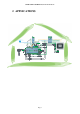
C-PRO CLIMA SISTEMA INSTALLER MANUAL 1 GENERALITIES 1.1 Description The c-pro CLIMA Climatic Modules allow to realise innovative control and regulation networks in distributed logic, for air-conditioning and heating systems in residential and commercial buildings, characterised by the most demanding and modern necessity for environmental comfort, system performance and energy savings.
C-PRO CLIMA SISTEMA INSTALLER MANUAL • Availability of MODBUS communication, from the Modules to a BMS system supervision system via a serial output, also suitable for the configuration phases or modification of controller parameters in the system installation or maintenance phases. All of these features mean an innovative control and regulation system, from high performance resulting in great system efficiency with consequent maximum energy saving.
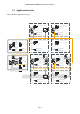
C-PRO CLIMA SISTEMA INSTALLER MANUAL 2 APPLICATIONS CAN network Personal Computer with supervision software "RICS" installed CAN network CAN network Page 7 CAN network
C-PRO CLIMA SISTEMA INSTALLER MANUAL 2.
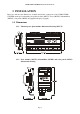
C-PRO CLIMA SISTEMA INSTALLER MANUAL 3 INSTALLATION Below we will show the dimensions, assembly and electric connections of the C-PRO CLIMA SYSTEM, made up from thermal power plant modules (MCCT), Zones (MCZN), Dehumidifiers (MCDE), solar panels (MCPS) and graphical displays (Vgraph). 3.1 Dimensions 3.1.1 Thermal power plant module dimensional drawing (MCCT). 3.1.2 Zone modules (MCZN), dehumidifier (MCDE) and solar panels (MCPS) dimensional drawing.
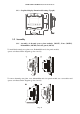
C-PRO CLIMA SISTEMA INSTALLER MANUAL 3.1.3 Graphical display dimensional drawing (Vgraph). 3.2 Assembly 3.2.1 Assembly of thermal power plant modules (MCCT), Zone (MCZN), Dehumidifier (MCDE) and solar panels (MCPS) To install the thermal power plant, zone, Dehumidifier and solar panels module, operate as indicated in the diagrams (points 1 and 2). To remove thermal power plant, zone, dehumidifier and solar panels module, use a screwdriver and operate as indicated in the diagrams (points 3 and 4).
C-PRO CLIMA SISTEMA INSTALLER MANUAL 3.2.2 Display Assembly (Vgraph) There are three possibilities for assembly of the Vgraph graphical display: 3.2.2.1 Wall recessed in 506E box 3.2.3 3.2.3.1 Wall-installation, on Evco CPVW00 support 3.2.3.
C-PRO CLIMA SISTEMA INSTALLER MANUAL 3.3 Electric connections 3.3.1 Thermal power plant electric connections (MCCT).
C-PRO CLIMA SISTEMA INSTALLER MANUAL C-PRO Mega Thermal power plant controller I/O Description Analogue inputs (NTC / 0-5V / 4-20mA) External air temperature – NTC A/I 1 CT Delivery temperature 1 – NTC A/I 2 CT Delivery temperature 2 – NTC A/I 3 CT Serial ports Rs485 modbus Rs485 At the c-pro CLIMA system modules CANbus Digital inputs (ON-OFF pocoverial-free contact) Alarm (block) Boiler D/I 1 CT Chiller – Heat pump alarm D/I 2 CT Delivery pump 1 flow switch (and/or thermal switch) D/I 3 CT Delivery pump 2
C-PRO CLIMA SISTEMA INSTALLER MANUAL 3.3.2 Zones electric connections (MCZN).
C-PRO CLIMA SISTEMA INSTALLER MANUAL 3.3.3 Dehumidifier electric connections (MCDE).
C-PRO CLIMA SISTEMA INSTALLER MANUAL 3.3.4 Solar panels electric connections (MCPS). C-PRO Micro solar panels controller I/O Description Analogue inputs (NTC / 0-5V / 4-20mA) DHW tank temperature (upper) (NTC) A/I 1 PS DHW tank lower temperature (NTC) A/I 2 PS Auxiliary temperature 1 (NTC) A/I 3 PS Solar panel 2 temperature (4-20 mA). Solar panel 1 temperature (4-20 mA).
C-PRO CLIMA SISTEMA INSTALLER MANUAL 3.
C-PRO CLIMA SISTEMA INSTALLER MANUAL 3.4.1 MCCT thermal power plant controller network configuration As the thermal power plant controller is the logical centre of the system controlled, it is first necessary to set how many MCZN zone regulators will be present in the system, following the procedure given below: 1. Enter the Installer General parameters menu of the MCCT regulator 2.
C-PRO CLIMA SISTEMA INSTALLER MANUAL 3.4.3 Network configuration of controllers for additional MCDE dehumidifiers Once the MCZN zone regulators have been configured, if present, it is possible to associate the relative regulators for additional MCDE dehumidifiers to the same. The regulator for dehumidifiers leaves the factory configured as regulator associated to zone 1(therefore with CANbus 22 address).
C-PRO CLIMA SISTEMA INSTALLER MANUAL 3.4.4 MCPS solar panels controller network configuration As the solar panels controller is the only possible controller of this type that can be installed in the system, in order to configure it just enable the presence of the MCPS regulator from the thermal power plant application, following the procedure given below: 1. Enter the Installatore Parametri generali (Installer, General parameters) menu of the MCCT regulator 2.
C-PRO CLIMA SISTEMA INSTALLER MANUAL 3.5 Displays network configuration For the final user, the c-pro CLIMA system envisions the use of a series of user terminals installed in zone, from which it is possible to display temperature, humidity, state of the zone and set the work set-points, time bands, etc.
C-PRO CLIMA SISTEMA INSTALLER MANUAL MCCT thermal power plant controller settings: Below find the settings to make on the MCCT regulator to make Vgraph a public terminal: From the Installer General parameters menu, enable the presence of the public V-graph display via Enab.
C-PRO CLIMA SISTEMA INSTALLER MANUAL MCCT thermal power plant controller settings: Below find the settings to make on the MCCT regulator to make Vgraph a private module: From the Installer General parameters disable the presence of the public V-graph display via Enab. V-GRAPH.
C-PRO CLIMA SISTEMA INSTALLER MANUAL MCCT thermal power plant controller settings: Below find the settings to make on the MCCT regulator to make Vgraph a private zone terminal: From the Installer General parameters menu, disable the presence of the public V-graph display via Enab. V-GRAPH parameter.
C-PRO CLIMA SISTEMA INSTALLER MANUAL 4 USER INTERFACE 4.1 Display and keyboard A unique incorporated interface is envisioned for the application (herein called built-in) in the MCCT controller with 4 x 20 characters alphanumerical display and several dedicated keys and LEDs. The built-in display of the MCCT controller is the only user interface available for the installer and the maintenance technician of the c-pro CLIMA system.
C-PRO CLIMA SISTEMA INSTALLER MANUAL There are also 2 LEDs present. - associated to the ESC key, it identifies the machine state Off: with machine off. On: with machine on. - associated to key K0, it identifies the presence or not of alarms Off: no alarm present. Flashing: with alarms present. 4.2 Navigation through the applications making up the system The c-pro mega MCCT controller represents the heart of the c-pro CLIMA system, also from a user interface point of view.
C-PRO CLIMA SISTEMA INSTALLER MANUAL 5 c-pro mega MCCT regulator Thermal power plant regulator 5.1 List of pages This paragraph presents the main pages and menus found in the MCCT application. As shown previously, the main menu is divided into 3 levels: user, maintenance technician and installer. A “States” section is also present that can be consulted freely, also necessary for navigation between modules.
C-PRO CLIMA SISTEMA INSTALLER MANUAL 5.2 Alarms/log menu This menu contains the functionality linked to the controller alarms and the alarms log of the system. 5.2.1 Alarms log To view the system alarms log (MCCT regulator and MCZN regulators), press ENTER on “hystorical alarms”.
C-PRO CLIMA SISTEMA INSTALLER MANUAL 5.3 Clock menu From this menu it is possible to set/modify the value of the date and real time that the c-pro mega MCCT controller propagates to the entire c-pro CLIMA system. To set/modify the date and/or real time, press ENTER on “Real time clock” and set the desired value, as shown in the following figure. If the ESC key is pressed from a setting page or 60 timeout seconds are allowed to pass, you go back to the main page of the application.
C-PRO CLIMA SISTEMA INSTALLER MANUAL 5.5 Installer menu The installer menu is level 2, i.e. used to insert the installer level password or higher in order to display/modify the parameters present in this branch. From this menu it is possible to view and set the configuration of the system managed from the MCCT application.
C-PRO CLIMA SISTEMA INSTALLER MANUAL 5.6 Main OFF page The main OFF page changes depending on the reason for which the unit is off. The unit in OFF alarm can be switched off completely using the key, digital input or supervisor. This type of display is temporary. When the 30 seconds time-out has passed, the controller will go back to the display of the main ON page, however indicating the OFF state of the unit. 5.
C-PRO CLIMA SISTEMA INSTALLER MANUAL 5.8 State pages By accessing the state pages from the ON main page, access the following four screens representing the machine states of the c-pro mega MCCT controller and the entire controlled system. 5.8.
C-PRO CLIMA SISTEMA INSTALLER MANUAL 5.8.
C-PRO CLIMA SISTEMA INSTALLER MANUAL Pumps flow switches Run Pumps flow switches Nr. alarms/hour Network management Zone modul. enabling Maintenance L1 Pump mode Maintenance L1 Pump management Alarm delay Maintenance L1 Pump management ON delay Maintenance L1 Pump management OFF delay Maintenance L1 Pump management Mix.vlv. delay Maintenance L1 Pump management CH-HP delay Maintenance L1 Pump management Antigrip enab. Maintenance L1 Temp. regulation Setpoint S LT Maintenance L1 Temp.
C-PRO CLIMA SISTEMA INSTALLER MANUAL Maintenance L1 Mixing valve S Setpoint 2 Maintenance L1 Mixing valve S Fix setpoint Maintenance L1 Mixing valve W Mode Maintenance L1 Mixing valve W Min.Ext.T. Maintenance L1 Mixing valve W Max.Ext.T. Maintenance L1 Mixing valve W Setpoint 1 Maintenance L1 Mixing valve W Setpoint 2 Maintenance L1 Mixing valve W Fix setpoint Maintenance L1 M.Valve regulation Prop. Band Maintenance L1 M.Valve regulation Integr. time Maintenance L1 M.
C-PRO CLIMA SISTEMA INSTALLER MANUAL Maintenance L1 Probes calibration Temperature Delivery 1 temperature probe calibration (expressed in °C) 0.0 -10.0 10.0 Default Min Max NTC NTC NTC N.O. N.C. N.O. 0.0 0.0 100.0 1 0 16 Setting the number of zone MCZN modules present in the system 1 0 8 Setting the number of delivery lines present in the system 1 0 2 * The same menu is also available for the delivery 2 line 5.9.
C-PRO CLIMA SISTEMA INSTALLER MANUAL 4800 baud 9600 baud 19200 baud General parameters MODBUS network Parity General parameters MODBUS network Stop bit Line 1 configuration Line type Line 1 configuration M.Valve enable Configure line 1 Pump DIn alr Type of MODBUS communication parity MODBUS communication Bit Stop position DELIVERY LINES Type of delivery line 1 H.T. = High temperature (radiators) L.T. = Low temperature (floor) Enabling of mixing valve 1 EVEN NO EVEN 1b 1b 2b L.T. H.T. L.T.
C-PRO CLIMA SISTEMA INSTALLER MANUAL 5.10 State of the unit There are several procedures for switching the unit on/off: 1) Via the relative On/Off key Switch-on: press the relative key for about 2 seconds: if all of the other conditions enabled are present, the machine goes to "ON". Switch-off: press the relative key for about 2 seconds: the machine goes to "OFF" mode. 2) Via the On/Off from digital input control (ONOFF d.
C-PRO CLIMA SISTEMA INSTALLER MANUAL supervisor or switch-off is requested from key, the power plant goes into the relative OFF state. The alarms that cause this state are: - Delivery 1 probe alarm - Delivery 2 probe alarm The machine works normally again when the alarm has been reset. 5.
C-PRO CLIMA SISTEMA INSTALLER MANUAL 6 c-pro micro MCZN regulator Zone regulator 6.1 List of pages This paragraph presents the main pages and menus found in the MCZN application. As shown previously, the general menu is divided into 2 levels: maintenance technician and installer are also present along with "Zones State", “ON/OFF” and "System Network" sections for free consultation. The latter is also necessary for navigation among modules.
C-PRO CLIMA SISTEMA INSTALLER MANUAL 6.2 Main page The main page is displayed during the ON state: Name of the MCZN regulator to which access has been Summer/Winter operational mode MCZN regulator state: ON = regulation in progress OFF = regulator OFF ALARM = MCZN regulator general alarm CT ALARM = MCCT regulator alarm off-line By pressing the DOWN key, it is possible to select whether to access the Zones State pages of the Main Menu, the On/Off pages or System Network pages, described below.
C-PRO CLIMA SISTEMA INSTALLER MANUAL 6.4 Main menu By accessing the pages of the main menu from the “Main Page” of the MCZN regulator, access the setting pages of all regulator functioning parameters organised in the following sub-menu: 6.4.1 Alarms menu This menu contains the information linked to the alarms present/active in the MCZN controller. The MCZN regulator alarms log is contained in the MCCT thermal power plant regulator alarms log.
C-PRO CLIMA SISTEMA INSTALLER MANUAL 6.4.3 Maintenance menu The maintenance menu is level 1, i.e. used to insert the maintenance level password or higher in order to display/modify the parameters present in this branch.
C-PRO CLIMA SISTEMA INSTALLER MANUAL CANbus (c-pro CLIMA controllers network) and Modbus (towards the RICS supervision system or other BMS systems). Entering the ZONES (Zone A / Zone B) menu, it is possible to define the main/construction features relative to the zones enabled and controlled by the MCZN regulator i.e.
C-PRO CLIMA SISTEMA INSTALLER MANUAL 6.7 Configuration parameters Below find a list of all configuration parameters contained in the MAINTENANCE menu and INSTALLER managed by the MCZN application. A brief description is supplied for every parameter, the range of acceptable values, unit of measurement and the default value proposed. The menus are structured following the logic given in the respective description paragraphs 7.4.3 and 7.4.4. 6.7.
C-PRO CLIMA SISTEMA INSTALLER MANUAL Zone A Maintenance Temp. integration Winter delay Zone A Maintenance Temp. integration Summer delta Zone A Maintenance Temp. integration Summer delay Zone A Maintenance T.Ext.Set variation MinTExt S Zone A Maintenance T.Ext.Set variation MaxTExt S Zone A Maintenance T.Ext.Set variation MinTExt Set W Zone A Maintenance T.Ext.Set variation MaxTExt Set W Zone A Maintenance T.Ext.Set variation Mode TExt.W Zone A Maintenance T.Ext.
C-PRO CLIMA SISTEMA INSTALLER MANUAL Zone A Maintenance Dehumidifier Alarm Reset type Zone A Maintenance Dehumidifier Alarm Delay Zone A dehumidifier alarm reset type -AUTOMATIC -MANUAL AUTOMA TIC AUTOMA TIC MANUA L 0 1 Default Min Max Type of measure input for analogue inputs 1 and 2 NTC NTC NTC Type of measure input for analogue inputs 3 and 4 4-20mA NTC 4-20mA N.C. N.C. N.O. 2 0 2 UNIV. UNIV.
C-PRO CLIMA SISTEMA INSTALLER MANUAL Zone A setup Terminal units Zone A setup Sensor type Zone A setup T. probe pos. Zone A setup H. probe pos. Zone A setup Rem. set pos. Zone A setup Reg. type Zone A setup D output cfg Zone A setup Dehum. with H2O Zone A setup Zone probe signal Probe type Zone A setup Zone probe signal Min H. value Zone A setup Zone probe signal Max H. value Zone A setup R.Set calibr. Rem. dehumidifyer Enable control Rem.
C-PRO CLIMA SISTEMA INSTALLER MANUAL 6.8 State of the unit The state of the MCZN regulator is given by the state of the MCCT thermal power plant regulator. 6.9 State of Zone A and Zone B There are two ways to vary the state of Zones A and B: 1) Using the On/Off keyboard control Using the On/Off pages described in chapter 7.
C-PRO CLIMA SISTEMA INSTALLER MANUAL 7 c-pro Micro MCDE regulator Regulator for additional dehumidifiers 7.1 List of pages This paragraph presents the main pages and menus found in the MCDE application. As shown previously, the general menu is divided into 2 levels: maintenance technician and installer are also present along with "Zones State", “ON/OFF” and "System Network" sections for free consultation. The latter is also necessary for navigation among modules.
C-PRO CLIMA SISTEMA INSTALLER MANUAL 7.
C-PRO CLIMA SISTEMA INSTALLER MANUAL 7.4 Main menu By accessing the pages of the main menu from the “Main Page” of the MCDE regulator, access the setting pages of all regulator functioning parameters organised in the following sub-menu: 7.4.1 Alarms/log menu This menu contains the functionality linked to the controller alarms and the alarms log of the system. 7.4.2 Alarms log To view the MCDE regulator alarms log, press ENTER on “Hystorical alarms”.
C-PRO CLIMA SISTEMA INSTALLER MANUAL 7.4.5 Maintenance menu The maintenance menu is level 1, i.e. used to insert the maintenance level password or higher in order to display/modify the parameters present in this branch.
C-PRO CLIMA SISTEMA INSTALLER MANUAL MCZN zone regulator it is associated and the features of the serial communication parameters both CANbus (c-pro CLIMA controllers network) and Modbus (towards the RICS supervision system or other BMS systems). Entering the CO2 menu, it is possible to define the main/construction features relative to the CO2 sensor used, enabling or not the presence and defining the minimum and maximum calibration values.
C-PRO CLIMA SISTEMA INSTALLER MANUAL 7.7 Configuration parameters Below find a list of all configuration parameters contained in the MAINTENANCE menu (maintenance technician) and INSTALLER managed by the MCDE application. A brief description is supplied for every parameter, the range of acceptable values, unit of measurement and the default value proposed. The menus are structured following the logic given in the respective description paragraphs 8.4.5 and 8.4.6. 7.7.
C-PRO CLIMA SISTEMA INSTALLER MANUAL Booster Parameters Booster H Booster Parameters Booster C Booster Parameters Set deh1 in Booster Parameters Set deh2 in Booster Parameters Dehum. activ. CO2 parameters Enable reg.
C-PRO CLIMA SISTEMA INSTALLER MANUAL General parameters MODBUS network Idx General parameters MODBUS network Baud General parameters MODBUS network Parity General parameters MODBUS network Stop Modbus serial address Modbus communication speed (baud rate) - 1200Kb - 2400Kb - 4800Kb - 9600Kb - 19200Kb Type of Modbus communication parity - NO - ODD - EVEN Modbus communication Bit Stop position 1 1 247 9600Kb 1200Kb 19200Kb EVEN NO EVEN 1b 1b 2b No No Yes 0 0 5000 2000 0 5000 1 0 2 N
C-PRO CLIMA SISTEMA INSTALLER MANUAL 8 c-pro micro MCPS regulator Regulator for Solar Panels 8.1 List of pages This paragraph presents the main pages and menus found in the MCPS application. As shown previously, the main menu is divided into 2 levels: maintenance technician and installer are also present along with "States” and "System Network" sections for free consultation. The latter is also necessary for navigation among modules.
C-PRO CLIMA SISTEMA INSTALLER MANUAL 8.2 Main page The main page is displayed during the ON state: If flashing, thermal power plant OFFline DHW tank (lower) temperature (boiler) MCPS regulator state: ON = regulation in progress OFF = regulator OFF ALARM = MCPS regulator general alarm If flashing, c-pro CLIMA system in alarm By pressing the DOWN key it is possible to select whether to access the State, pages, the Main Menu or the System Network, described below.
C-PRO CLIMA SISTEMA INSTALLER MANUAL 8.3.
C-PRO CLIMA SISTEMA INSTALLER MANUAL 8.4 Main menu By accessing the pages of the main menu from the “Main Page” of the MCPS regulator, access the setting pages of all regulator functioning parameters organised in the following sub-menu: 8.4.1 Alarms/log menu This menu contains the functionality linked to the controller alarms and the alarms log of the system. 8.4.2 Alarms log To view the MCPS regulator alarms log, press ENTER on “storico allarmi (alarms log)”.
C-PRO CLIMA SISTEMA INSTALLER MANUAL 8.4.5 Set-point menu From this menu it is possible to display and set the temperature work set-point for the DHW tank and for the AUX1 auxiliary circuit. If the ESC key is pressed from a setting page or 240 timeout seconds are allowed to pass, you go back to the main page of the application. This level is not protected by a password. 8.4.6 Maintenance menu The maintenance menu is level 1, i.e.
C-PRO CLIMA SISTEMA INSTALLER MANUAL 8.4.7 Installer menu The installer menu is level 2, i.e. used to insert the installer level password or higher in order to display/modify the parameters present in this branch. From this menu it is possible to view and set the configuration of the DHW system, the solar panels system/s and the auxiliary system and their controls.
C-PRO CLIMA SISTEMA INSTALLER MANUAL 8.6 Configuration parameters Below find a list of all configuration parameters contained in the MAINTENANCE menu (maintenance technician) and INSTALLER managed by the MCPS application. A brief description is supplied for every parameter, the range of acceptable values, unit of measurement and the default value proposed. The menus are structured following the logic given in the respective description paragraphs 9.4.6 and 9.4.7. 8.6.
C-PRO CLIMA SISTEMA INSTALLER MANUAL Panels maintenance Stag.emergency Panels maintenance ON hyst. Panels maintenance OFF hyst. Panels maintenance Temperature limits HT setpoint Panels maintenance Temperature limits HT hyst. Panels maintenance Temperature limits LT setpoint Panels maintenance Temperature limits LT hyst. Aux 1 Maintenance Mode Aux 1 Maintenance Contr.
C-PRO CLIMA SISTEMA INSTALLER MANUAL Aux 1 Maintenance Mode DHW maintenance Delay Flow switches Alr ON delay Flow switches Alr RUN delay Flow switches Auto reset n° 8.6.2 Label I/O configuration AIn 1 I/O configuration AIn 2 I/O configuration AIn 3 I/O configuration AIn 4 I/O configuration DIn General parameters Solar panels General parameters Aux 1 circuit General parameters DHW probes Upper probe en. General parameters DHW probes Upper probe en.
C-PRO CLIMA SISTEMA INSTALLER MANUAL General parameters CANbus address CANbus serial address General parameters Baud rate CANbus communication speed (baud rate) -20Kbit -50Kbit -125Kbit -500Kbit General parameters MODBUS network Idx Modbus serial address General parameters MODBUS network Baud General parameters MODBUS network Parity General parameters MODBUS network Stop Solar panels Probes offset Panel 1 Solar panels Probes offset Panel 2 Solar panels P.1 sensor Min. Solar panels P.1 sensor Max.
C-PRO CLIMA SISTEMA INSTALLER MANUAL 9 Regulations This chapter will state all main regulations made by the c-pro CLIMA system. At the side of the title of every paragraph, in brackets find the control module or modules involved in these regulations. It can therefore be immediately understood from which application to set the function and if the function is available or not in the system available, depending on the presence or not of the control modules indicated. 9.
C-PRO CLIMA SISTEMA INSTALLER MANUAL Important parameters: MCZN: Installer menu General parameters Local zones nr. MCZN: Installer menu Zones Zona A(B) Delivery line MCZN: Installer menu Zones Zone A(B) Terminal units MCZN: Installer menu Zones Zone A(B) Sensor type MCZN: Installer menu Zones Zone A(B) T. probe pos. MCZN: Installer menu Zones Zone A(B) Reg.
C-PRO CLIMA SISTEMA INSTALLER MANUAL 9.1.3.2 Variation of the zone work set-point for "manual compensation" (MCZN module) By activating the work set-point variation function for “manual compensation” by installing a remote set-point variator it is possible (e.g. the EVSET01 accessory), to allow the final user to increase/lower the active zone work set-point within the pre-established limits, by simply acting on the pocoveriometer distinguished by the + / - indication.
C-PRO CLIMA SISTEMA INSTALLER MANUAL 9.1.4 Zone anti-freeze protection (MCZN module) During the winter functioning mode when the system is not running (i.e.
C-PRO CLIMA SISTEMA INSTALLER MANUAL MCDE: Maintenance Menu Booster parameters Mode MCDE: Maintenance Menu Booster parameters Booster H MCDE: Maintenance Menu Booster parameters Booster C MCDE: Maintenance menu Booster parameters Set deh1 in. MCDE: Maintenance menu Booster parameters Set deh2 in. MCDE: Maintenance Menu Booster parameters Dehum. activ. 9.2 Regulation of the delivery temperature (MCZN, MCCT modules) 9.2.
C-PRO CLIMA SISTEMA INSTALLER MANUAL 9.2.2 Management of the utilities set-up for heating delivery water: boiler (and heat pump (MCCT module) During winter regulation, once the water has been put into circulation in the system, whenever the delivery work set-point is not satisfied, the c-pro CLIMA system will send a request to the thermal power plant controller for the activation of the utilities set-up for heating of the delivery water.
C-PRO CLIMA SISTEMA INSTALLER MANUAL 9.2.3 Management of the utility set-up for cooling delivery water: the chiller (MCCT module) During summer regulation, once water has been made to circulate in the system, whenever the delivery temperature is above the Summer delivery work set-point of the hysteresis value, then a chiller activation request will be sent. Correct chiller functioning is controlled via a chiller-heat pump digital input alarm which, whenever activated, will block the utility immediately.
C-PRO CLIMA SISTEMA INSTALLER MANUAL Important parameters: MCCT: Installer Menu I/O configuration Analog out. 1(2) MCCT: Installer Menu Delivery lines Line 1(2)configuration M.Valve 1(2) enable MCCT: Maintenance Menu Delivery lines 1(2) Mixing valve S Mode MCCT: Maintenance Menu Delivery lines 1(2) Mixing valve W Mode MCCT: Maintenance Menu Delivery lines 1(2) M. valve regulation Prop. band MCCT: Maintenance Menu Delivery lines 1(2) M. valve regulation Integr.
C-PRO CLIMA SISTEMA INSTALLER MANUAL 9.2.7 Dew point control (MCCT, MCZN modules) During the SUMMER functioning mode, the work set-point of the mixing valve (or delivery valve) will be continuously monitored and if necessary modified in order to check the dew point of each individual active Zone. The dew point is the temperature at which a mass of air must be cooled at constant pressure, so that it becomes saturated (i.e.
C-PRO CLIMA SISTEMA INSTALLER MANUAL 9.2.9 Delivery anti-freeze protection (MCDE module) During the winter functioning mode when the system is not running (i.e.
C-PRO CLIMA SISTEMA INSTALLER MANUAL 9.3.3 Zone humidity work set-point (MCZN module) The zone humidity work set-point is decided in manual mode via the relative maintenance technical parameters present in the c-pro micro MCZN zone regulator or automatically, set by the final user via programmed weekly time bands. To set the automatic humidity work set-points (Economy and Comfort set-points), consult the c-pro CLIMA system user manual.
C-PRO CLIMA SISTEMA INSTALLER MANUAL 9.3.5 Management of the dehumidifiers on/off digital inputs The zone c-pro micro MCZN has two dehumidifiers on/off digital inputs (one for every zone) Whenever the digital input finds the logic level "disabled", the corresponding additional dehumidifier will be considered in OFF stare and all of the relative regulations will be disabled. In order to make this control active the inputs must be enabled via the relevant maintenance technician parameters.
C-PRO CLIMA SISTEMA INSTALLER MANUAL 9.5 Regulation of the DHW tank temperature for the DHW water (MCPS module) 9.5.1 Regulation principle Whenever the c-pro micro MCPS module is present and enabled in the system, the system will automatically consider the presence of a DHW storage tank in the system for the DHW.
C-PRO CLIMA SISTEMA INSTALLER MANUAL 9.5.3 DHW tank work set-point (MCPS module) The DHW tank work set-point is established in manual mode from the relevant Set-point menu present in the main menu of the c-pro micro MCPS regulator. Depending on the dimensions of the system, the DHW tank can have just one temperature probe (DHW tank probe) or two different temperature probes (DHW tank upper and lower probe).
C-PRO CLIMA SISTEMA INSTALLER MANUAL Important parameters: MCPS: Installer menu General parameters Aux1 Circuit MCPS: Installer Menu General parameters pumps alarm CFG AUX1 pump MCPS: Maintenance Menu Aux1 Management Setpoint MCPS: Maintenance Menu Aux1 Management Hysteresis MCPS: Maintenance Menu Aux1 Management Probe offset MCPS: Maintenance Menu Aux1 Management Mode 9.5.
C-PRO CLIMA SISTEMA INSTALLER MANUAL 9.6 Management and configuration of the heating solar panel circuits (MCPS module) Whenever the c-pro micro MCPS module for solar panels is present and enabled in the system, one or two heating solar panel circuits management can be enabled, with the function of heating the DHW in the DHW tank.
C-PRO CLIMA SISTEMA INSTALLER MANUAL 9.6.1 Management of the solar panels circuits circulation (MCPS module) The controller for the MCPS solar panels can manage up to 2 thermal solar panel circuits, each with relative circulation pump. The circulation pump is activated on temperature request of the DHW tank, whenever the conditions described in previous paragraph 9.5.4. are satisfied.
C-PRO CLIMA SISTEMA INSTALLER MANUAL 9.6.3 Management and setting the stagnation emergency for solar panels circuits (MCPS module) Whenever the temperature of the water in one of the solar panels circuits exceeds the maximum temperature value accepted for the system of the hysteresis value, then the regulator for c-pro micro MCPS solar panels will start a special stagnation emergency cycle.
C-PRO CLIMA SISTEMA INSTALLER MANUAL 9.7 Other regulations 9.7.1 Management and setting of the periodic anti-grip cycle (MCCT, MCPS modules) The function has the purpose of preventing the blocking of the pumps and valves present in the cpro CLIMA system during system standstill due to any deposits present in the system or due to the formation of crystalline aggregates (lime scale or other) on the mechanical seals of the pumps and valves.
C-PRO CLIMA SISTEMA INSTALLER MANUAL - FLOW: every activation of the digital input, after a delay time or from the activation of the pump (start) or from the activation of the input itself (normal conditions), will cause the deactivation of the relative circulation pump.
C-PRO CLIMA SISTEMA INSTALLER MANUAL Page 88
C-PRO CLIMA SISTEMA INSTALLER MANUAL Version 1.02 June 2011. Code 144CLIMA0E02. File 144CLIMA0E02.pdf. This publication is exclusive property of Evco, which prohibits reproduction and distribution,, unless expressly authorised by Evco itself. Evco does not assume any liability regarding the features, technical data and possible errors in this document or deriving from use of the same. Evco cannot be held responsible for any damage caused by the failure to comply with the warnings.
OFFICES Evco Via Mezzaterra 6, 32036 Sedico Belluno ITALIA Tel. 0437-852468 Fax 0437-83648 info@evco.it www.evco.it OVERSEES BRANCHES Control France 155 Rue Roger Salengro, 92370 Chaville Paris FRANCE Tel. 0033-1-41159740 Fax 0033-1-41159739 control.france@wanadoo.fr Evco Latina Larrea, 390 San Isidoro, 1609 Buenos Aires ARGENTINA Tel. 0054-11-47351031 Fax 0054-11-47351031 evcolatina@anykasrl.com.ar Evco Pacific 59 Premier Drive Campbellfield, 3061, Victoria Melbourne, AUSTRALIA Tel.