
Installer manual Owner manual


C-PRO CLIMA SISTEMA INSTALLER MANUAL
Page 33
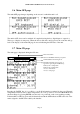
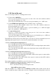
5.8.3 State and access page of the MCZN zone regulators modules
The state and access page to the MCZN zone regulators modules shows the network state of the
MCZN regulators described in the previous illustration.
Pressing ENTER on the “>” in the top right of the screen, returns to the DELIVERY LINE L1 state
page.
Pressing ENTER on the selected MCZN module state (with MCZN module present, enabled and
on-line) the MCZN application can be accessed.
When the 30 seconds time-out has passed or by pressing ESC, the controller will go back to the
display of the main ON page.
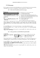
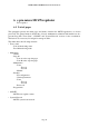
5.9 Configuration parameters
Below find a list of all configuration parameters contained in the MAINTENANCE menu
(maintenance technician) and INSTALLER managed by the MCCT application.
A brief description is supplied for every parameter, the range of acceptable values, unit of
measurement and the default value proposed.
The menus are structured following the logic given in the respective description paragraphs 6.4 and
6.5.
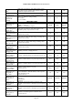
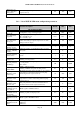
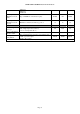
5.9.1 List of MAINTENANCE menu configuration parameters
Label
Parameter description Default Min Max
GENERAL PARAMETERS
ONOFF dig. input Enable ON OFF digital input No No Yes
W/S keyboard Enabling of Summer/winter from keyboard S S W
W/S d.input Enabling of Summer/winter from digital input No No Yes
W/S BMS Enabling of Summer/winter from BMS Yes No Yes
W/S auto Enabling automatic Summer/winter switch-over No No Yes
T. ext. W (°C)
Temperature below which automatic summer/winter
switch-over takes place, relative to the external
temperature (expressed in °C)
5.0 -30.0 30.0
T. ext. S (°C)
Temperature above which automatic winter/summer
switch-over takes place, relative to the external
temperature (expressed in °C)
30.0 -30.0 30.0
W/S delay (h)
Permanence duration of the external temperature
over/below the threshold established so that
summer/winter switch-over and vice versa takes place
automatically (expressed in hours)
1 0 255
Loads antigrip day Day of the week for performing the antigrip cycle Friday Sunday Saturday
Loads antigrip
Time
Time of performance of the antigrip cycle 2 0 24
Pumps flow switches
start
Delay time on activation of the alarms relative to the 1
and 2 delivery flow switches from system start-up
(expressed in seconds)
30 0 255
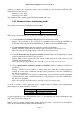
Indication of the state of the relative MCZN zone module:
+ = zone present, enabled with active zones
+ = zone present, enabled with non-active zones
? = zone present, enabled but off-line
A = zone present, enabled in alarm state
! = zone present but disabled
* = zone not present/not configured