PROGRAMABLE CONTROLLERS FOR AIR HANDLING UNITS APPLICATION MANUAL CODE 144AHU0K0E07
C-PRO KILO AHU APPLICATION MANUAL Important Please read the instructions herein before installing and using the device. Follow all instructions and suggestions for installing and connecting the device; keep these instructions in a safe place as you may need them for future reference. Ensure that this device is properly discarded in accordance with local government regulations as they pertain to the disposal of electrical and electronic devices. Pag.
C-PRO KILO AHU APPLICATION MANUAL Summary Important....................................................................................................................................2 1 GENERAL.........................................................................................................................6 1.1 Description.................................................................................................................6 2 APPLICATIONS .................................................
C-PRO KILO AHU APPLICATION MANUAL 6.5.2 Modulating Regulation ..........................................................................................53 6.5.3 Modulating regulation with steps to enable ...........................................................54 6.5.4 Air quality sensor cycles........................................................................................55 6.5.5 Fan status ..........................................................................................................
C-PRO KILO AHU APPLICATION MANUAL 6.15.9 Programming key.................................................................................................79 7 DIAGNOSTICS...............................................................................................................80 7.1 Manual and automatic alarms ....................................................................................80 7.1.1 Manual alarms..........................................................................................
C-PRO KILO AHU APPLICATION MANUAL 1 GENERAL 1.1 Description The air handling units (AHU) contain various programmable application controls providing the user with the widest range of solutions and combinations which can be modified according to construction requirements, including the destination in which the plant subject is installed.
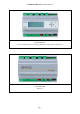
C-PRO KILO AHU APPLICATION MANUAL C-PRO KILO AHU Version with built-in LCD screen display (alfanumeric display with 4 x 20 characters) C-PRO KILO EXP Expansion Pag.
C-PRO KILO AHU APPLICATION MANUAL 2 APPLICATIONS The air handling device can be operated under the following three modes: 1) 2) 3) 4) 5) 6) Air handling unit usage during the winter time only. Air handling unit usage during the summer time only. Air handling unit usage during the summer and winter, with humidity. Air handling unit usage during the summer and winter, with humidity and heat recuperation. Air handling unit regulated by 2 coils without dehumidification.
C-PRO KILO AHU APPLICATION MANUAL 2.1 Air handling device usage during the winter only Pag.
C-PRO KILO AHU APPLICATION MANUAL 2.2 Air handling device usage during the summer only Pag.
C-PRO KILO AHU APPLICATION MANUAL 2.3 Air handling device usage during the summer and winter, with humidity Pag.
C-PRO KILO AHU APPLICATION MANUAL 2.4 Air handling unit usage during the summer and winter, with humidity and heat recuperation Pag.
C-PRO KILO AHU APPLICATION MANUAL 2.5 Air handling unit regulated by 2 coils without dehumidification Pag.
C-PRO KILO AHU APPLICATION MANUAL 2.6 Air handling unit dehumidification regulated Pag.
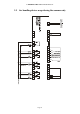
C-PRO KILO AHU APPLICATION MANUAL 2.7 Layout of connection - C-PRO KILO AHU The connection layout of the controller is shown below, with related tables explaining the significance of inputs and outputs. JA Connections for analogue signals Conn. Label Description JA-1 AI1 Analogue inputs n.1 (for NTC probe) JA-2 AI2 Analogue inputs n.2 (for NTC probe) JA-3 AI3 Analogue inputs n.3 (for NTC probe) JA-4 AI4 Analogue inputs n.
C-PRO KILO AHU APPLICATION MANUAL JD: Connection for the cut-phase output EVDFAN1 (analogue output 1; not utilized) Conn. Label Description JD-1 VDC Supplying power to cut-phase module EVDFAN1 JD-2 AO1 Cut-phase output module EVDFAN1 In order to utilize the cut-phase module EVDFAN1, it is necessary to supply power to the controller in an alternate current; the current that powers the controller must be the same current as that which is used to power the module.
C-PRO KILO AHU APPLICATION MANUAL 2.8 Layout of connection - EXP KILO The following presents the connection layout of KILO expansion, with relative tables indicating inputs and outputs. JA Connector for the analogue signals Pag.
C-PRO KILO AHU APPLICATION MANUAL Conn. JA-1 JA-2 JA-3 JA-4 Label AI1 AI2 AI3 AI4 JA-5 AI5 JA-6 JA-7 JA-8 GND +5V +12V Description Analogue input n.1 (for NTC probe) Analogue input n.2 (for NTC probe) Analogue input n.3 (for NTC probe) Analogue input n.4 (for NTC probe / transducers 0-20 mA / transducers 4-20 mA); ratiometric transducers 0-5 V upon request Analogue input n.
C-PRO KILO AHU APPLICATION MANUAL JF: Connector for supplying power to the expansion Conn. Label Description JF-1 V≅ Expansion power supply (24VAC / 20 … 60 VDC) JF-2 V≅ Expansion power supply (24VAC / 20 … 60 VDC) JG: Connector for connecting to controllore Conn. Label Description JG-1 VDC Power supply (not utilized) JG-2 GND Common JG-3 DATA Serial in tension JM-JL-JI-JH: Connection for the digital outputs (electromechanical relays) Conn. Label Description JM-4 NO1 Contact normally open relay n.
C-PRO KILO AHU APPLICATION MANUAL 3 NETWORK COMPONENTS & ACCESSORIES Pag.
C-PRO KILO AHU APPLICATION MANUAL 4 USER INTERFACE 4.1 Display and keyboard Application requires an interface incorporated into the controller (later referred to as built-in) with an alfanumeric display containing 4 x 20 characters and various keys and dedicated led. 4.1.1 Buit-in interface The built-in interface is directly integrated into the controller.
C-PRO KILO AHU APPLICATION MANUAL - : ESC key, identifies current state of machine. Off: machine on On: machine off (or machine alarms OFF) Slow flashing light: machine digital inputs off Quick flashing light: machine supervisor off 4.2 Page listing The following paragraph presents the principle pages and menus presented in the application manual. As previously discussed, the general menu is divided into four sections: User, Maintenance Operator, Installation Operator, and Constructor.
C-PRO KILO AHU APPLICATION MANUAL In the upper right hand corner of the above image appears a “>” indicating that you may navigate to another page. This is done by placing the cursor on the “>” and then pressing ENTER; this will bring you to the following page. In the upper left hand corner of the above image appears a “<” indicating that you may navigate to the preceding page by placing the cursor on the “<” and then pressing ENTER. 4.2.
C-PRO KILO AHU APPLICATION MANUAL 4.2.4 Maintenance Operator Menu Access to the Maintenance Operator Menu for level 2 requires a password from a maintenance operator (or superior) in order to view/modify the parameters presented in this branch. In this Menu it is possible to view the status of various devices, inputs and outputs utilized by the application.
C-PRO KILO AHU APPLICATION MANUAL In the REGOLAZIONI (REGULATIONS) Menu you can set/view parameters for various specific regulations: ⋅ compensation regulation Set Point ⋅ cycles for air quality sensors Within the VENTILATORI (FAN), BATTERIE (COIL), UMIDITA’(HUMIDITY), RECUPERO(RECUPERATION), SERRANDA ARIA (AIR SHUTTER) and POMPE (PUMPS) menus you may set the the related parameters to manage the devices: ⋅ regulation parameters ⋅ timetable ⋅ operation In the SICUREZZE(SECURITY) Menu you can find all the pa
C-PRO KILO AHU APPLICATION MANUAL The CONFIGURAZIONE(CONFIGURATION) Menu allows you to set/view the parameters relating to the characteristics used to configure the device. ⋅ unit type ⋅ coil number ⋅ device enablement ⋅ utilization of the expansion In the HARDWARE IN Menu you can set the positions of the digital inputs. In the HARDWARE OUT Menu you can set the positions of the analogue and digital inputs. 4.2.
C-PRO KILO AHU APPLICATION MANUAL 4.2.9 Main ON page When the unit is turned ON the following main pages will appear: If ALARM indicates that there are active alarms Mode of operation during summer/winter Set Point ambient temperature Set Point ambient humidity Active functions on the unit from which you may access the status page, by pressing ENTER on the “>”. By pressing the ESC key you will able to view the alarm and history pages.
C-PRO KILO AHU APPLICATION MANUAL The following page summarizes the main values pertaining to the regulation of the delivery temperature: Value of delivery probe and regulation Set Point Requested heating (and cooling in the case where a single coil is used) and actual Set Point for heating Requested cooling and actual Set Point for cooling The following page summarizes the main values pertaining to the regulation of humidity: Value of ambient humidity probe and regulation Set Point Requested humidificati
C-PRO KILO AHU APPLICATION MANUAL 4.2.12 History pages In order to view the alarm history, choose STORICO (HISTORY) from the general Menu. Alternatively, on the main page you can press the ESC key in order to view the following page: Press ENTER on “Mostra STORICO >>”(Show History>>). If no elements are present you will see “NO ALARMI”(NO ALARMS) written on the screen.
C-PRO KILO AHU APPLICATION MANUAL 5 CONFIGURATION PARAMETERS To follow is a list of all the parameters which are managed by the application. A brief description will be furnished for each parameter explaining the range of acceptable values, units of measurement, the reccomended default values and the menus in which they can be found.
C-PRO KILO AHU APPLICATION MANUAL 5.1 Directory of configuration parameters Code PT01 PT02 PT03 Level 1 MOd E SEtC Description parameter Default Min Max UM Menu CLOCK MENU This menu is accessible only if PG03=1 Begin nocturnal operating mode End nocturnal operating mode Offset of Set Point nocturnal operating mode 00:00:00 00:00:00 0.0 00:00:00 00:00:00 -20.0 23:59:59 23:59:59 20.0 °C OR OR OR 1 0 1 - UT 24.
C-PRO KILO AHU APPLICATION MANUAL activate PM80 PM81 PM82 PM83 PM84 PM85 PM87 PM88 PM89 PSd2 Level 3 PC01 PC02 PC03 PC04 PC05 PC06 PC07 PC08 PF01 PF02 PF03 PF04 PF05 PF08 PF09 PF10 Pb01 Pb02 Calibration of the ambient air temperature probe Calibration of the delivery air temperature probe Calibration of the external air temperature probe Calibration of the ambient humidity probe Calibration of the air temperature expulsion probe Calibration of the anti-freeze temperature probe Calibration of the pre-h
C-PRO KILO AHU APPLICATION MANUAL not present Pb03 Neutral zone for the regulation of temperature 4.0 0.0 20.0 °C IS-B Pb05 Maximum shifting for Set Point calculation running of delivery 0.0 0.0 20.0 °C IS-B 5.0 0.0 20.0 °C IS-B 30.0 30.0 0.0 0.0 100.0 100.0 % % IS-B IS-B 60 0 999 Sec IS-B 6 10 0 0 100 100 % % IS-U IS-U 0 0 999 Sec IS-U NO (0) NO (0) YES (1) - IS-U YES (1) NO (0) YES (1) - IS-U 22.0 PH03 PH04 °C IS-U 3.0 0.0 20.0 °C IS-U 10.0 0.
C-PRO KILO AHU APPLICATION MANUAL PS09 Minimum variation regulation for operating the external air shutters 0.0 0.0 90.0 % IS-SE PS10 Fixed value for opening external air shutters 50.0 0.0 100.0 % IS-SE PS11 Offset at Set Point during winter (at ambient temp.) until the external air shutters remain closed during winter operating mode 2.0 0.0 30.0 °C IS-SE 2.0 0.0 20.0 °C IS-SE 4.0 0.0 20.0 °C IS-SE 8.0 1.0 100.0 10.0 1.0 200.0 600 100 0 0 5.
C-PRO KILO AHU APPLICATION MANUAL PA01 PA02 PA03 PA04 PA05 PA06 PA08 PA09 PA10 PA11 PA15 PA16 PA20 PA21 PA24 PA25 PA26 PA28 PA29 PA30 PA31 PA32 PA33 PA35 PA36 PA37 PA38 PA39 PA40 PA41 PA42 PA45 PH01 PH02 PH03 PH04 PH05 PH06 Enable alarms during hours of fan operation Enable alarms during hours of pump operation Signal alarms during hours of operation on alarm relay Probe alarm delay Signal alarm probe on alarm relay Expansion alarm delay Signal delivery fan alarm on alarm relay Signal pickup fan alarm on
C-PRO KILO AHU APPLICATION MANUAL PH13 PH14 modes utilizing the keyboard (ModE parameter) Enable machine start-up/shut-down using the Digital inputs Enable the change in summer/winter operating modes utilizing the Digital inputs Enable machine start-up/shut-down as supervisor Enable the change in summer/winter operating modes as supervisor Modbus card address Baud Rate of comunication for the card (0=1200, 1=2400, 2=4800, 3=9600, 4=19200) ModBus parity (0=none, 1=Odd, 2=Even) Stop Bit ModBus (0=1bit, 1=2b
C-PRO KILO AHU APPLICATION MANUAL PH52 PH53 PH60 Logistics of Digital inputs used for the alarm flux status Logistics of Digital inputs for alarm fire-smoke Logistics of alarm relay PH15 Restoring the manufacturers’ defualt parameters PSd3 Level 4 Password Installation Operator Level (3) PG00 CONFIGURATION PARAMETERS Upon modification of these parameters it is advised to remove and delete the card feed Unit type: 1: Winter operating mode only 2: Summer operating mode only 3: Winter and summer operat
C-PRO KILO AHU APPLICATION MANUAL PG14 PSd4 Hd01 Hd02 Hd03 Hd05 Hd06 Hd07 Hd08 Hd10 Hd11 Hd13 Hd15 Hd16 Hd17 Hd18 Hd19 Hd20 HF01 HF02 HU01 HS01 HS02 HP01 HP02 Hr01 HE01 0: Disabled 1: At cross flow 2: Using two coils 3: Rotating On/Off (DO) 4: Rotating Modulating (AO) Post-heating with electrical resistance: 0: Operation disabled 1: One stage of resistance 2: Two stages of resistance 3: Three stages of resistance Password for Constructor Level (4) HARDWARE IN PARAMETERS Positioning of Digital inputs whil
C-PRO KILO AHU APPLICATION MANUAL HE02 HE03 HA01 HA02 HA04 HA05 HA06 HA07 HA08 HA09 Position of the digital output of the second stage of electrical resistance Position of the digital output of the third stage of electrical resistance Position of the digital output of the alarm relay Position of the digital output for dirty filter indicator alarm or dirty recuperator Position of the analogue output of the heating valves (or single for heating/cooling in case the unit is at single coil) Position of the ana
C-PRO KILO AHU APPLICATION MANUAL 6 REGULATIONS 6.1 Unit status There are additional procedures for the start-up/shut-down of the unit: 1) Using the On/Off key (parameter, PH05=1) Startup: press the related key for approximately 2 seconds: if all the other enabled conditions are present, the machine will turn “ON”. Shutdown: press the related key for approximately 2 seconds: the machine will turn “OFF”.
C-PRO KILO AHU APPLICATION MANUAL 6.1.1 Alarm OFF status When the machine is turned on an additional status, OFF da alarm (Alarm Off) exists. This shuts down the unit, all devices, and closes the external air shutters completely until the alarm conditions are restored. The central alarm will shut down to OFF status if there is no digital / supervisor consent or shut down is requested via the keyboard.
C-PRO KILO AHU APPLICATION MANUAL 6.2 Unit Type While the machine is turned off, using the parameter PG00 in the COSTRUTTORE (CONSTRUCTOR) Menu, it is possibile to choose the type of unit that you wish to utilize. Based on the value of the parameters, different defualts become available for the positioning of inputs and outputs. The regulation and other parameters which correspond to diverse funtionalities can be modified manually according to user requirements.
C-PRO KILO AHU APPLICATION MANUAL 6.2.1 Unit in WINTER operating mode (PG00=1) The MOdE parameter can be setup by default in INVERNO (WINTER). Unit at single coil PG01=1. The fan regulations can be setup by default in On/Off (PF01=1). The primary regulation can be setup by default on the valve (PG04=1). The regulation of the shutter is fixed (PG07=2).
C-PRO KILO AHU APPLICATION MANUAL 6.2.2 Unit in SUMMER operating mode (PG00=2) The MOdE parameter can be setup by default in ESTATE (SUMMER). Unit at single coil PG01=1. The fan regulations can be set up by default in On/Off (PF01=1). The primary regulation can be set up by default on the valve (PG04=1). The regulation of the shutter is fixed (PG07=2).
C-PRO KILO AHU APPLICATION MANUAL 6.2.3 Unit operation during WINTER/SUMMER WITH HUMIDITY (PG00=3) The MOdE parameter can be set up by default in INVERNO (WINTER). Unit at single coil PG01=1. The fan regulations can be set up by default in inverter with On/Off (PF01=3). The primary regulation can be set up by default on the valve (PG04=1). The primary regulation starts with valves set on default (PG04=1). The regulation of the shutter is enabled for free-cooling/free-heating (PG07=1, PS01=1).
C-PRO KILO AHU APPLICATION MANUAL 6.2.4 Unit for operation in WINTER/SUMMER with humidity and recuperation (PG00=4) The MOdE parameter starts while set on default on WINTER Unit at single coil PG01=1. The regulation of the fans starts while set on default on inverter with On/Off (PF01=3). The primary regulation starts while set on default on the valve (PG04=1). The regulation of the shutter is enabled for free-cooling/free-heating (PG07=1, PS01=1). The recuperator in use is that at cross flow PG13=1.
C-PRO KILO AHU APPLICATION MANUAL 6.2.5 Unit with 2 coils without dehumidification (PG00=5) The MOdE parameter starts while set by default on WINTER. This unit provides the utilization of the expansion (PG02=1). The regulation of the fans starts while on its default setting on the inverter with On/Off (PF01=3). The number of coils is PG01=2; the post-heating is managed by the resistance PG14=3. The dehumidification is disabled PG12=0.
C-PRO KILO AHU APPLICATION MANUAL PIN DO1 DO2 DO3 DO4 DO5 DO6 DO7 DO8 DO9 DO10 DO11 DO12 DO13 DO14 USCITE DIGITALI Delivery fan Pickup fan Not utilized Opening of external air shutter Closing of external air shutter Dirty filter indicator Alarm Shutter by-pass recuperator Heating pump Cooling pump Electrical resistance – first stage Electrical resistance – second stage Electrical resistance – third stage Not utilized RTC system clock present. Pag.
C-PRO KILO AHU APPLICATION MANUAL 6.2.6 Unit with 3 coils with dehumidification (PG00=6) The MOdE parameter with default setting on WINTER. This unit provides utilization of the expansion (PG02=1). The regulation of the two fans starts while set on default on the inverter with On/Off (PF01=3). The number of coils configured is PG01=3; the post-heating is guaranteed by the third coil. The dehumidification is enabled PG12=1.
C-PRO KILO AHU APPLICATION MANUAL DO1 DO2 DO3 DO4 DO5 DO6 DO7 DO8 DO9 DO10 DO11 DO12 DO13 DO14 Delivery fan Pickup fan Humidifier on/off Opening external air shutter Closing external air shutter Dirty filter indicator Alarm Shutter by-pass recuperator Heating pump Cooling pump Not utilized Not utilized Not utilized Not utilized RTC system clock present. Pag.
C-PRO KILO AHU APPLICATION MANUAL 6.3 Operating mode during summer/winter The operating modes can assume the following values: Parameter “MOdE” 0=COOL – SUMMER 1=HEAT – WINTER Description Summer operation Winter operation There are additional procedures which allow you to set the operating mode of the unit: 1) Using the MOdE parameter in the user Menu (function enabled by using parameter PH06) Set – Positioned on the ModE parameter, press the ENTER key, modify the values using the UP and DOWN keys.
C-PRO KILO AHU APPLICATION MANUAL 6.4 Setting the RTC When the card remains without tension for a few days, the RTC (Real Time Clock) system clock discharges requiring it to be reset to the correct date and time while also restoring the eventual alarm (if enabled, PA40=1). In this case, upon macchine startup the following page will appear allowing you to set the RTC: Once the clock has been configured press OK to update the RTC and then enter into the main application page.
C-PRO KILO AHU APPLICATION MANUAL SUMMER operating mode SEtC (SEtH): Set Point ON OFF PF02: Diff. T. Ambient WINTER operating mode SEtH: Set Point ON OFF PF02: Diff. T. Ambient Note. It is necessary to set the positions of the two digital outputs for the fan’s parameter HF01(delivery) and HF02(pickup). If a parameter is equal to zero the signal from the relative fan will not be enabled on any digital output. 6.5.
C-PRO KILO AHU APPLICATION MANUAL SUMMER operating mode Fan Speed PF04: Max. % SEtC (SEtH): Set Point PF03: Min. % PF02: Diff. T. ambient WINTER operating mode Fan Speed PF04: Max. % SEtH: Set Point PF03: Min. % PF02: Diff. T. ambient The regulations for both fans are identical, therefore there is only one regulation ramp which is brought to a single analogue output. You will be required to set the position from the Constructor Menu by going to parameter HA07.
C-PRO KILO AHU APPLICATION MANUAL The regulations for both fans are identical, therefore there is only one regulation ramp which is brought to a single analogue output. The position needs to be set from the constructor Menu by going to parameter HA07. If HA07=0 the signal is not enabled on any analogue output. It is also possible to associate at the two steps of enablement two digital outuputs for the fans by setting the positioning parameters HF01(for delivery) and HF02(for pickup). 6.5.
C-PRO KILO AHU APPLICATION MANUAL A fan operating manually is nevertheless sensitive to eventual alarms, in this case the status will be that of Alarm. 6.5.6 Security inputs You must manage the security of the “thermal fan” for both fans that have been configured. In order to enable the alarm you must set from the constructor Menu the positions in which the digital inputs will be connected for the security evaluations (Hd05, Hd07).
C-PRO KILO AHU APPLICATION MANUAL 6.6 Main regulations The application wants to maintan comfortable conditions within the internal ambient; in order to achieve this the two main regulations are made on two fundamental units of measurement: temperature and humidity. Both regulations provide a Neutral Zone (parameter Pb03 for the temperature and PU02 for the humidity) in which there is no requested regulation.
C-PRO KILO AHU APPLICATION MANUAL 6.7 Cooling and Heating Regulations When the primary regulation is made on the valve (PG04=1) it is possible to manage and to regulate the command for the cooling /heating valve. The regulation comes on a flowing Set Point calculated as shifting from the regulation ambient temperature Set Point. The valve is commanded using a proportional algorithm (P), or a proportional integral (PI). The reference probe is that of the delivery temperature. Note.
C-PRO KILO AHU APPLICATION MANUAL 6.7.2 Valve module regulation In order to utilize it is necessary to set the position (at greater than zero) of the analogue outputs in the constructor menu using the HA05 parameter (cooling valve) and HA04 (heating valve). If HA05=0 and HA04=0 the indicator is not enabled on any of the analogue outputs. In order to utilize only a proportional regulation you need to only set the integral time to zero (Pb02=0).
C-PRO KILO AHU APPLICATION MANUAL 6.8 Post-Heating This may be performed using one coil (PG01=3) or, alternatively, utilizing electrical resistances (PG14>0). The post-heating serves two main purposes: integration of heat in heating or compensation in the dehumidification phase in order to realize the amount of heat lost (i.e. drop in temperature) during dehumidification.
C-PRO KILO AHU APPLICATION MANUAL SetPoint - Delivery 3° resistance 2° resistance Neutral Zone 1° resistance Pb01 x 2 T. Delivery Within each insertion/removal of resistances a certain amount of time (parameter Pb20) must elapse in order to avoid simultaneous occurrences. Using the Hd13 parameter it is possible to enable the thermal alarm of the resistance, which provides for the immediate shutdown of the device. Note.
C-PRO KILO AHU APPLICATION MANUAL 6.9 Dehumidification In order to adjust the comfort of the ambient it is necessary to also consider the humidity in the air and regulate it based on a determined desired Set Point percentage (PU01) and at a neutral zone (PU02) in which the humidity conditions are acceptable and do not require any intervention. The regulation of the dehumidification is proportional-integral, to render it only proportional you need to only set the integral time to zero (PU04=0).
C-PRO KILO AHU APPLICATION MANUAL cooling valve opening to dehumidify in order to contrast the continous decrease in temperature (required by the dehumidification) and rapidly returning to the desired conditions in temperature. This action has a more immediate effect on temperature and allows for energy savings, optimizing coil control. No limitation SetPoint - Delivery Heating coil 100 % Post-Heating coil Maximum limitation Neutral Zone Limited action on cooling coil for dehumidification 0% Pb01 T.
C-PRO KILO AHU APPLICATION MANUAL zone (PU02). If the ambient humidity probe is present it is possible to command the humidifier using On/Off switch or by using the module. Humidity management is enabled by activating the parameter PG06>0, in the constructor menu. The ambient air humidity probe is also activated (PH41=1), if the probe is disabled or in error dehumidification management will be inhibited.
C-PRO KILO AHU APPLICATION MANUAL 6.10.3 Modulating humidifier In order to utilize the modulating regulation of the humidifier it is necessary to set the parameter PG06 to 2. The position of the analogue output that is connected to the humidifier also needs to be set (parameter HA08). PU01: Set Point 100% Neutral Zone 0% PU03: Diff. UR% ambient Note. To utilize this function it is necessary to enable the ambient humidity probe by setting parameter PH41 to 1.
C-PRO KILO AHU APPLICATION MANUAL 6.11 External Air Shutters The program provides the managment of a motorized shutter for the intake of external air to support the ambient temperature regulation.
C-PRO KILO AHU APPLICATION MANUAL Enable Free-Cooling in temperature Enable Free-Heating in temperature PS13: SetFC PS13: SetFH T. Ambient – T. External PS12: Diff. T. External – T. Ambient PS12: Diff. Note. It is necessary to enable the utilization of the external air temperature probe (PH40=1). If the probe is in error the regulation is disabled. 6.11.
C-PRO KILO AHU APPLICATION MANUAL 6.11.4 Free-Cooling and Free-Heating Regulation The regulation of the free-cooling/free-heating commands the opening of the external air shutter.
C-PRO KILO AHU APPLICATION MANUAL 6.11.5 Air quality control The external air shutter may be used to replace the air upon request by the appropriate probe (VOC/CO2). It is necessary to enable the parameter PS02=1, and the regulation probe for the air quality (PH46>0). The external air shutter can be commanded based on the regulation probe at set point (PS20) and at the relative differential (PS21). Note. If the air quality probe is in error the regulation is inhibited. The probe can be one of two types: 4.
C-PRO KILO AHU APPLICATION MANUAL 6.11.7 Shutter status In the user interface you can identify the operating status of the shutters which will present you with one of the following: 1. Disabled: the shutter is not managed by the controller. In the user interface you will see the symbol “ - ” when in this state. 2. Closed: the shutter is closed. In the user interface you written“CHIUSA”(CLOSED) and a value of 0.0%. when in this state will see 3. Opening: the shutter is in the process of opening.
C-PRO KILO AHU APPLICATION MANUAL 6.12 Heat Recuperators When the quantity of renewed air is substantive the air treatment centers provide a system which recovers the expulsion air for a better exercise of energy costs.
C-PRO KILO AHU APPLICATION MANUAL After the delay Pr05 the by-pass shutter will activate in oder to allow for defrosting. When the temperature rises above the allowable value the shutter will deactivate while the recuperator restarts. Note. It is necessary to set the position of the digital output of the recuperators by-pass shutter using the parameter dedicated to the recuperator, Hr01. When the regulation probes are in error this function is disabled. 6.12.
C-PRO KILO AHU APPLICATION MANUAL Note. It is necessary to set the position of the digital output of the recuperator, using the dedicated parameter, Hr01. The external temperature probe must also be enabled (PH40=1). When the regulation probes are in error this function is disabled. PG13=4. Modulating regulation Pr01: Set Point Recuperator 100% 0% Pr02: Diff. | T.Expulsion – T.External | Note.
C-PRO KILO AHU APPLICATION MANUAL 6.13 Heating/Cooling Pumps A simple method for managing the two circulation pumps (for heating/cooling) is provided. In order to enable the cooling pump you need to set paramater PG10 to 1. To enable the heating pump you will need to set parameter PG11 to 1 in the Consructor menu. Based on the requirement you may choose between two regulations by going to parameter PP01 (continuous regulation, On/Off regulation).
C-PRO KILO AHU APPLICATION MANUAL 6.13.3 Pump status Both pumps may assume any of the following operating states: 7. Disabled: the pump is not managed by the controller. In the user interface you will see the symbol “ - ” when in this state. 8. Off: the pump is off. In the user interface you will see written “OFF” when in this state. 9. Waiting for shutdown: the pump is in the process of shutting down, and is in queue for scheduled protection.
C-PRO KILO AHU APPLICATION MANUAL 6.14 Unit at single coil (seasonal) In this type of unit (PG01=1) there is only one dedicated valve for heating and cooling and, if enabled, there is a single circulation pump; the operating mode (parameter MOdE) determines which behavior to utilize. In the same way all the regulations (fans, freecooling/free-heating, regulations of set-point, alarms, etc..) are distinguished based on the operating mode.
C-PRO KILO AHU APPLICATION MANUAL 6.15 Management (various) 6.15.1 Single or distinct Set Point It is possible to manage a single regulation Set Point for summer/winter, or to set two different ones. If the parameter PH27 Enables the single/distinct Set Point is set to 1 the Set Point is singular (only one parameter), otherwise the Set Point is distinct (two distinct parameters: SEtH and SEtC).
C-PRO KILO AHU APPLICATION MANUAL is possible to set the logic for the Digital inputs by setting the parameter PH50: 0=NO (Normally open), 1=NC (Normally closed). In order to enable this function you will need to enable parameter PH25 Enable variation Set Point from Digital inputs and set the position on which the related Digital inputs will be connected (parameter Hd03). If this parameter is set to 0, the function is disabled. Note.
C-PRO KILO AHU APPLICATION MANUAL 6.15.7 Last date of maintenance In the Menu Manutentore->Funzionamento (Maintenance Operator->Operation) you will find a page with the ability to memorize the last date of maintenance for the implant. By pressing on “Aggiorna” (Update) the old date which is in the system will automatically be updated with the new correct date; updating the maintenance date can be done at parameter PM90. 6.15.
C-PRO KILO AHU APPLICATION MANUAL 7 DIAGNOSTICS The application is in the process of managing a series of alarms and related fans, pumps, probes and other operations from the central unit. Based on the various types of alarms it is possible to configure a rearmament (if manual or automatic), an eventual delay in signal and of other actions which will follow in a specific case. When one or more alarms are active the alarm icon flashes.
C-PRO KILO AHU APPLICATION MANUAL 7.2 Table of Alarms The following is a list of all the alarms managed by the application. The order of presentation is the same as the order of presentation for the active alarms. All alarms can be viewed even when the mahcine is off.
C-PRO KILO AHU APPLICATION MANUAL 7.2.1 Air Flow Meter Alarm The flowmeter can be managed after the initial startup phase of the unit and after the Ritardo flussostato da reset PA28 (Flowmeter delay from reset PA28): once this time elapses, if the contact indicates lack of flow, the alarm will immediately go off. During normal operation the flow sensor is continuously monitored: if the contact indicates lack of flow for a period greater than that at parameter PA29 the alarm will immediately go off.
C-PRO KILO AHU APPLICATION MANUAL 7.3 Alarm relay The program provides the possibility to manage a relay for a configurable alarm. For each type of alarm there is a parameter that permits you to choose whether that particular alarm must be signaled on the the alarm relay. Additional alarms can be addressed at relay. The position of the digital output dedicated to signal the alarm can be set using the parameter HA01, if equal to zero the alarm relay will not be utilized.
C-PRO KILO AHU APPLICATION MANUAL 8 MODBUS VARIABLES It is possible to control the application using a supervisor, utilizing the Modbus protocol. The communication comes across an interface (serial RS485) which is already integrated in the controller. To follow are the various states/parameters exported by the application. 8.
C-PRO KILO AHU APPLICATION MANUAL Bit1=AL17, Bit2=AL18, Bit3=AL19, Bit4=AL20, Bit5=AL21, Bit6=AL22, Bit7=AL23, Bit8=AL24, Bit9=AL25, Bit10=AL26, Bit11=AL27, Bit12=AL30, Bit13=AL31 R/W 770 PackedAlarm_2 0 0 65535 1025 Status_OnOff_bySUP 0 0 1 R/W 1026 Status_MOde_bySUP 0 0 1 R/W 1027 Status_En_OffsetSP_bySUP 0 0 1 R/W 1281 CLOCK_RTC ( Low ) 0 0 214748364 7 R/W 1282 CLOCK_RTC ( High ) 1283 StatusUnit 0 0 5 R/W 1284 v_MOdE 0 0 1 R/W Winter Set Point or Set Point uni
C-PRO KILO AHU APPLICATION MANUAL 0=Disabilitato, 1=OFF, 2=Opening, 3=ON, 4=Closing, 5=ALL, 6=Allineamento R/W 0% -100.00% R/W 1293 Status_AirExtShutter 0 0 6 1294 Position_AirShutter 0.00 0.00 100.00 1537 PT01_Start_NightTB ( Low ) 0 0 86399 R/W 1538 PT01_Start_NightTB ( High ) 1539 PT02_End_NightTB ( Low ) 0 0 86399 R/W 1540 PT02_End_NightTB ( High ) 1541 PT03_OffsetSetPoint_Night 0.0 -20.0 68.
C-PRO KILO AHU APPLICATION MANUAL 1562 PM26_EnManualHumidifier 0 0 1 R/W 1563 PM27_ForceHumidifier 0 0 100 R/W 1564 PM80_Calibration_EnvironmentProbe 0.0 -9.9 50.0 R/W 1565 PM81_Calibration_AirSupplyProbe 0.0 -9.9 50.0 R/W 1566 PM82_Calibration_AirExternalProbe 0.0 -9.9 50.0 R/W 1567 PM83_Calibration_HumidityEnvironment_Probe 0 -9 9 R/W 1568 PM84_Calibration_AirSupplyPressure_Probe 0.0 -14.5 14.
C-PRO KILO AHU APPLICATION MANUAL 1=FixedOpen 1593 PS02_SetWinterMinLimit_AirExternalShutter 14.0 -15.0 158.0 R/W 1594 PS03_SetSummerMaxLimit_AirExternalShutter 28.0 -15.0 158.0 R/W 1595 PS04_Diff_AirExternalShutter 8.0 0.0 86.0 R/W 1596 PS05_MinRegulationValue_AirExternalShutter 0.00 0.00 100.00 R/W 1597 PS06_MaxRegulationValue_AirExternalShutter 100.00 0.00 100.
C-PRO KILO AHU APPLICATION MANUAL 1625 PA26_AlarmAirFilter_alarmDO 1 0 1 R/W 1626 PA28_AlarmAirFlowSwitchDelay_Reset 30 0 999 R/W 1627 PA29_AlarmAirFlowSwitchDelay 5 0 999 R/W 1628 PA30_AlarmAirFlowSwitch_alarmDO 1 0 1 R/W 1629 PA31_ResetType_AlarmHumidifier 0 0 1 R/W 1630 PA32_HumidifierAlarm_Delay 2 0 999 R/W 1631 PA33_AlarmHumidifier_alarmDO 1 0 1 R/W 1632 PA35_EnableType_AntiFreezeAlarm 1 0 1 1633 PA36_AlarmAntiFreeze_Delay 5 0 999 R/W 1634 PA37_Ala
C-PRO KILO AHU APPLICATION MANUAL 1658 PH28_EnableNightTimeBand 0 0 1 R/W 1659 PH32_TemperatureUM 0 0 1 R/W 1660 PH33_Press_UM 0 0 1 1661 PH40_EnableExternalProbe 0 0 1 R/W 1662 PH41_EnableHumidityEnvironmentProbe 0 0 1 R/W 1663 PH42_EnableAirPressureSupplyProbe 0 0 1 R/W 1664 PH50_Logic_DI_OnOff_SP_Mode_Remote 0 0 1 R/W 1665 PH51_Logic_DI_Alarm 0 0 1 R/W 1666 PH52_Logic_DI_AlarmAirflow 1 0 1 R/W 1667 PH53_Logic_DI_AlarmFire 1 0 1 R/W 1668 PH60_Lo
C-PRO KILO AHU APPLICATION MANUAL 1690 Hd20_PosDI_AlarmFire 0 0 7 R/W 1691 HF01_Pos_DO_SupplyFan 1 0 7 R/W 1692 HF02_Pos_DO_ReturnFan 2 0 7 R/W 1693 HU01_Pos_DO_Humidifier 0 0 7 R/W 1694 HS01_Pos_DO_OpenShutterAirExternal 4 0 7 R/W 1695 HS02_Pos_DO_OpenShutterAirExternal 5 0 7 R/W 1696 HP01_Pos_DO_Pump 0 0 7 R/W 1697 HA01_Pos_DO_GlobalAlarm 7 0 7 R/W 1698 HA02_Pos_DO_AirFilterSwicth 6 0 7 R/W 1699 HA05_Pos_AO_Valve_Heating_Cooling 2 0 3 R/W 1700
C-PRO KILO AHU APPLICATION MANUAL Pag.
C-PRO KILO AHU APPLICATION MANUAL Application Manual for C-PRO KILO AHU. Version 1.07 - December 2009. Code 144AHU0K0E07. File 144AHU0K0E07.pdf. This publication is the exclusive property of Evco. Any form of reproduction and circulation is strictly forbidden, unless specifically authorised by Evco. Evco declines any responsibility regarding features, technical data or any mistakes contained in this publication, or consequential from usage of the same.
HEADQUARTERS Evco Via Mezzaterra 6, 32036 Sedico Belluno ITALY Tel. 0437-852468 Fax 0437-83648 info@evco.it www.evco.it OVERSEAS OFFICES Control France 155 Rue Roger Salengro, 92370 Chaville Paris FRANCE Tel. 0033-1-41159740 Fax 0033-1-41159739 control.france@wanadoo.fr Evco Latina Larrea, 390 San Isidoro, 1609 Buenos Aires ARGENTINA Tel. 0054-11-47351031 Fax 0054-11-47351031 evcolatina@anykasrl.com.ar Evco Pacific 59 Premier Drive Campbellfield, 3061, Victoria Melbourne, AUSTRALIA Tel.