PROGRAMMABLE CONTROLLER FOR AIR HANDLING UNITS WITH CROSS FLOW HEAT RECOVERY APPLICATION MANUAL CODE 144SAVE00E01
C-PRO MICRO SAVE APPLICATION MANUAL Important Read these instructions carefully before installation and use and follow all recommendations regarding installation and for the electric connection; keep these instructions for future reference. The instrument must be disposed of according to local Standards regarding the collection of electric and electronic appliances.
C-PRO MICRO SAVE APPLICATION MANUAL Summary Important ............................................................................................................................................................................ 2 Summary............................................................................................................................................................................. 3 1 GENERALITIES ....................................................................................
C-PRO MICRO SAVE APPLICATION MANUAL 1 GENERALITIES 1.1 Description The application is dedicated to the control and regulation of the Air Handling Units with cross flow recovery heat exchanger. There are two solutions available: • COMPACT Control: Responds to minimum requirements and the Standards. • COMPLETE Control: Integrates the heating and high recovery efficiency functions to the Base solution.
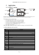
C-PRO MICRO SAVE APPLICATION MANUAL 2 Applications 2.1 COMPACT solution The picture above shows a principle layout. It is intended for indicating the presence of the components, not their position, in the AHU controlled by the EVCO device. It is also NOT intended for indicating the real layout of the AHU.
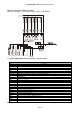
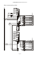
C-PRO MICRO SAVE APPLICATION MANUAL Electric connections with 3-speed fans Note: For driving the 3-speed fans (Digital output) set PG10=DO 2.1.
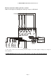
C-PRO MICRO SAVE APPLICATION MANUAL Electric connections with 1 speed fans + variator Note: For driving the modulating fans (Analogue output) set PG10=AO (*) The control of the recovery heat exchanger By-Pass damper can be either digital or analogue, by setting the PG03 parameter.
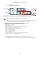
C-PRO MICRO SAVE APPLICATION MANUAL 2.2 COMPLETE solution The picture above shows a principle layout, it is intended for indicating the presence of the components, not their position, in the AHU controlled by the EVCO device. It is also NOT intended for indicating the real layout of the AHU. N.B. 1) The coil electric heater is an alternative to the hot water coil. 2) The CO2 probe is an optional just in the 3-speed fans version.
C-PRO MICRO SAVE APPLICATION MANUAL 2.2.
C-PRO MICRO SAVE APPLICATION MANUAL Electric connections with 3-speed fans Page 10
C-PRO MICRO SAVE APPLICATION MANUAL 2.2.
C-PRO MICRO SAVE APPLICATION MANUAL Electric connections with 1 speed fans + variator Page 12
C-PRO MICRO SAVE APPLICATION MANUAL 2.3 Connection lay out for C-PRO MICRO CAN Below find the connection lay out of the C-PRO MICRO controller with tables relevant to the meaning of the inputs and outputs. C-PRO MICRO connections Connector 1: Connection for the relay outputs Conn. Code Description C1-1 DO1 Relay n.1 normally open contact C1-2 COMMON DO1 Common relay n.1 C1-3 DO2 Relay n.2 normally open contact C1-4 COMMON DO2 Common relay n.2 C1-5 DO3 Relay n.
C-PRO MICRO SAVE APPLICATION MANUAL Connector 3: Connector for the analogue output (optional, not available in the day versions) Conn. Code Description (Version V+I) C3-1 AO2 0-10VDC C3-2 GND Common analogue output C3-3 AO3 4-20mA Description (Version I+I) C3-1 AO2 4-20mA C3-2 GND Common analogue output C3-3 AO3 4-20mA Description (Version V+V) C3-1 AO2 0-10VDC C3-2 GND Common analogue output C3-3 AO3 0-10Vdc Connector 4: Connector for low voltage signals Conn.
C-PRO MICRO SAVE APPLICATION MANUAL 2.4 Connection lay out for C-PRO EXP MICRO CAN Below find the connection lay out of the expansion with tables relevant to the meaning of the inputs and outputs. Connector 1: Connection for the relay outputs Conn. Code Description C1-1 DO1 Relay n.1 normally open contact C1-2 COMMON DO1 Common relay n.1 C1-3 DO2 Relay n.2 normally open contact C1-4 COMMON DO2 Common relay n.2 C1-5 DO3 Relay n.3 normally open contact C1-6 COMMON DO3 Common relay n.3 C1-7 DO4 Relay n.
C-PRO MICRO SAVE APPLICATION MANUAL 3 Network components and accessories Page 16
C-PRO MICRO SAVE APPLICATION MANUAL 4 User interface 4.1 Display and keyboard Both control solutions (compact and complete) use the Vgraph user terminal equipped with LCD graphic display 128x64 pixel and 6 keys. The terminal can be panel mounted (IP 65 with optional gasket) on the unit or remote using EVCO wall box or in wall recess boxes type “506”. Besides the EVCO front plates it is possible to use BTicino “Living” or “Light” series plates. 4.1.
C-PRO MICRO SAVE APPLICATION MANUAL 4.2 List of pages This paragraph presents the main pages and menus present in the application. The general menu is divided into three levels: user, installer and manufacturer, there is also a menu for the management of the system clock and some free access state pages.
C-PRO MICRO SAVE APPLICATION MANUAL The range of values accepted for the passwords is: -999 / 9999. If no action is taken on a menu after 4 minutes the password inserted expires and it must be entered again. 4.2.3 User Menu The User menu is on level 1, that is the level 1 (or higher) password must be taped in for entering the menu and display/modify the parameters present in this branch. By pushing the RIGHT key from this mask it is possible to access the page used for changing the password (PSd1). 4.
C-PRO MICRO SAVE APPLICATION MANUAL 4.2.5 RTC Menu This menu contains the functionalities linked to the system RTC: ⋅ the setting of the clock ⋅ setting the COMFORT/ECONOMY time bands To enter this menu, press ENTER on the RTC mask from the main menu. In this page it is possible to set the system clock and the two time periods of the fans’ automatic working (parameters PT01 and PT02). By pushing the ESC key from this menu it is possible to go back to the general menu. 4.2.
C-PRO MICRO SAVE APPLICATION MANUAL 4.2.7 Main OFF page The main OFF page changes depending on the reason why the unit is OFF. There are three possibilities: 1. Unit OFF: Unit switched-off pushing the relevant key 2. Unit OFF by Start-Stop: Unit ON by key but OFF due to digital contact DI/2 Start-Stop in “Stop” position 3. Unit OFF by Supervisor: Unit ON by key but OFF due to a Modbus command from the supervision module. 4.
C-PRO MICRO SAVE APPLICATION MANUAL COMPLETE VERSION Air temperature set point for main temperature control (supply/return) Alarm icon: appears when there are active alarms. If all of them have been viewed the icon becomes fixed, otherwise (some active alarms not viewed) the icon keeps flashing. Information regarding the fans working mode: - COMFORT: Comfort period automatic control - COMFORT+P.: Comfort period automatic control WITH presence sensor active. - ECONOMY: Economy period automatic control.
C-PRO MICRO SAVE APPLICATION MANUAL 4.2.11 Log pages To display the alarms log, select HISTORIAN from the general menu or press ESC from the main page to display this page: move the cursor on “Show HISTORIAN >>” and push the ENTER key.
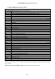
C-PRO MICRO SAVE APPLICATION MANUAL 5 Configuration parameters Below are listed all parameters managed by the application. A brief description, the range of acceptable values, unit of measurement, the default value proposed and the menu in which it is found is supplied for every parameter.
C-PRO MICRO SAVE APPLICATION MANUAL Code PM02 PM03 PM90 Parameter description MAINTENANCE Max number of fans working hours. The relevant alarm occurs over this limit Supply fan working hours Return fan working hours Last maintenance date PM11 Anti-freeze air temperature probe offset PM01 Default Min Max UM Menu 20000 0 100000 Hours IS-MA 0 0 0 0 100000 100000 Hours Hours IS-MA IS-MA IS-MA 0.0 0.0 -10.0 -18.0 10.0 18.
C-PRO MICRO SAVE APPLICATION MANUAL Code Level 3 PG01 PG02 PG03 PG04 PG05 PG06 PG08 PG09 PG10 PSd1 PSd2 PSd3 PF06 PF07 PF08 PF09 PF10 PF11 PS01 PS02 PS05 Pr01 Pr02 Pr03 Parameter description Default Min Max UM Menu Notes MANUFACTURER MENU CONFIGURATION PARAMETERS After modification of these parameters it is recommended to remove and then re-apply the power supply to the board.
C-PRO MICRO SAVE APPLICATION MANUAL Code PA03 PA05 PA06 PA08 Parameter description ALARM PARAMETERS Enabling of supply/return fans thermal overload alarm Enabling of differential pressure switch alarm Delay of differential pressure switch alarm Signals differential pressure switch alarm on alarm relay PA09 Anti-freeze alarm active on hot water coil PA10 Anti-freeze alarm delay on hot water coil PA12 Activates the heaters thermal switch alarm PA13 PA16 PA17 Signals heaters thermal overload alarm on
C-PRO MICRO SAVE APPLICATION MANUAL 5.2 COMPLETE solution list of configuration parameters Code Level 1 Parameter description USER MENU USER Default Min Max SPHM Supply temperature heating setpoint 22.0 PH01 PH02 SPHR Return temperature heating setpoint 20.
C-PRO MICRO SAVE APPLICATION MANUAL Code PF03 PF04 Parameter description FANS Type of fans regulation: 0: Manual 1: Automatic 2: Automatic with presence sensor 3: Automatic with CO2 sensor Fans speed in COMFORT period Fans speed in ECONOMY period PF05 Fans speed in RTC error PF01 PF12 PF13 Fans speed in COMFORT with presence sensor active Speed in case of « non working » day PF14 Set point CO2 for Speed 1 and 2 PF15 PF21 PF22 PF23 Set point CO2 for Speed 2 and 3 Speed variator value correspondin
C-PRO MICRO SAVE APPLICATION MANUAL Code Parameter description VARIOUS PARAMETERS Default Min Max PH01 Minimum temperature value -15.0 -20.0 -4.0 PH02 PH02 Maximum temperature value 95.0 PH01 PH03 PH04 Minimum CO2 probe PPM value Maximum CO2 probe PPM value Enables unit switch-on/off from “Start/Stop” digital input Enables unit switch-on/off from supervisor 0 0 PH05 PH06 UM Menu IS-V 0 PH03 110.0 230.
C-PRO MICRO SAVE APPLICATION MANUAL Code PF06 PF07 PF08 PF09 PF10 PF11 Pb02 Pb03 Pb04 Pb05 Pb06 PS01 PS02 PS05 Parameter description FANS Minimum time that must pass for the switchon/off of each individual step of the fans Fans temperature setpoint for anti-freeze protection of the recovery heat exchanger Fans differential for anti-freeze protection of the recovery heat exchanger Minimum stand-by time before requesting switch-off of a further fan step Fans differential regulation for the by-pass of the
C-PRO MICRO SAVE APPLICATION MANUAL Code PA03 Parameter description ALARM PARAMETERS Enabling of outlet/return fans thermal switch alarm PA05 Enabling of differential pressure switch alarm PA06 Delay of differential pressure switch alarm Signals differential pressure switch alarm on alarm relay PA08 PA09 Anti-freeze alarm active on hot water coil PA10 Anti-freeze alarm delay on hot water coil PA12 Activates the heaters thermal overload alarm PA13 PA16 PA17 Signals heaters thermal switch alarm
C-PRO MICRO SAVE APPLICATION MANUAL 6 REGULATIONS 6.1 State of the unit There are several unit switch-on/off procedures: 1) Via the relevant ON/OFF key Switch-ON: press the relevant key for about 2 seconds, if all the conditions are fulfilled the unit starts working (“ON” mode). Switch-OFF: press the relevant key for about 2 seconds, the unit stops working (“OFF” mode).
C-PRO MICRO SAVE APPLICATION MANUAL 6.1.1 OFF state for alarm When the machine is active and an heavy alarm occurs the unit switches into the OFF due to alarm status. In this case the unit and all devices are switched OFF and the dampers are completely closed until the alarm condition has been reset. When the unit is OFF for alarm it is possible to switch to the other OFF states by means of the relevant digital input, key or supervisor.
C-PRO MICRO SAVE APPLICATION MANUAL Set the PH99 parameter to “YES”(1) and wait until it becomes “NO”(0) again on the display. The system automatically restores all parameters’ default values. Note: After this operation switch OFF and back ON power supply to the board to prevent for malfunctioning. 6.
C-PRO MICRO SAVE APPLICATION MANUAL 6.6 Functionality of the COMPACT control solution This control solution offers the base functionality present also in the "complete" solution. 6.6.1 Supply and return fans The program manages two fans, supply and return, independently with a 3 steps control logic. This can be achieved using 3 digital output or one analogue output to pilot a speed variator with 3 speed levels.
C-PRO MICRO SAVE APPLICATION MANUAL 6.6.1.5 Fans status Each of the two fans can be in the following working states: 1. OFF: the fan is OFF. 2. ON V1: the fan is ON at speed 1. 3. ON V2: the fan is ON at speed 2. 4. ON V3: the fan is ON at speed 3. 5. Switch-ON stand-by: the fan is to be switched-on. Timing is in progress, e.g. stand-by due to pre-start of the outside air damper. The status shows the switch-on stand-by for each of the individual speeds. 6.
C-PRO MICRO SAVE APPLICATION MANUAL If the temperature T is between Tg and Tg + Tdiff (default 3°C, can be modified by parameter PF08) the current speed is maintained. Only when the temperature T becomes T ≥ Tg + Tdiff the fan speed returns to the normal condition (i.e. at the speed set by the user). 6.6.2.
C-PRO MICRO SAVE APPLICATION MANUAL 6.6.3.1 Cyclical defrosting with minimum temperatures The set point must be determined along with its differential for the activation of the defrosting cycle. Pr01: Setpoint ON OFF T. Anti-freeze Pr02: Diff.
C-PRO MICRO SAVE APPLICATION MANUAL 6.7 Features of the COMPLETE control solution Al functions of the COMPACT version are included in this version. Below are listed only the additional features of the COMPLETE control solution. 6.7.1 Post-Ventilation By setting the parameter PG05=1 it is possible to decide whether to run the fans for a time configured on parameter PF11, also after unit switch-OFF. If the function is active when the unit stops the fans keep working for further PF11 seconds. 6.7.
C-PRO MICRO SAVE APPLICATION MANUAL 6.7.3 Fresh air intake damper It is possible to manage an optional motorised damper (can be enabled by parameter PG04=1) for fresh air intake purpose. The damper is managed via ON/OFF (digital) activation. The damper can be either fully open or fully closed, modulation is not possible as well as a minimum opening. When the fans are requested to start first the damper is opened and, after a delay configured on parameter PS01, the fans are activated too.
C-PRO MICRO SAVE APPLICATION MANUAL Anti-freeze safety on hot water circuit (AL04) The anti-freeze mechanical thermostat (digital input DI7) is mounted downstream the coil either inside or outside the pipe.
C-PRO MICRO SAVE APPLICATION MANUAL 6.7.4.4 Heaters over temperature protection with automatic reset By setting the parameter PA16=1(high temperature) it is possible to decide whether to use the supply high temperature alarms or not.
C-PRO MICRO SAVE APPLICATION MANUAL 7 DIAGNOSTICS The application can manage a series of alarms relevant to the fans and the devices configured. Depending on the various types of alarm it is possible to configure a manual or automatic reset, a possible delay and the actions to carry out in the specific case. When one or more alarms are active the alarm icon on the main page flashes, if configured (PH20=1) and only with the machine ON the buzzer is also activated.
C-PRO MICRO SAVE APPLICATION MANUAL 7.2 Alarms table Below is a list of all alarms managed by the application. The order of presentation is the same as the order of active alarms occurrence. The alarms can be displayed also with the machine in OFF status.
C-PRO MICRO SAVE APPLICATION MANUAL 7.4 Alarms log The controller record the ALARMS LOG in a non-volatile area of the memory organised as FIFO (First In First Out), that is a list of the last 100 alarms occurred. To display the alarms log, select LOG from the General menu or press ESC from the main page to display this page: Move the cursor on “Show HISTORIAN>>>” and push the Enter key.
C-PRO MICRO SAVE APPLICATION MANUAL 8 MODBUS VARIABLES The controller can be managed by a supervisor via Modbus protocol. The communication takes place via optional TTL/RS485 serial interface outside the controller. The various states/parameters exported from the controller are shown below. 8.1 ModBus exporting table Addr Base 0 0x0100 Addr Base Name 1 257 Packed_DI 0x0180 385 Packed_DO 0x0200 513 0x0201 Value 0 Min 0 Max Description Mode 65535 Bit1=DI1, Bit2=DI2, Bit3=DI3, ...
C-PRO MICRO SAVE APPLICATION MANUAL Bit4=AL20, Bit5=AL21, Bit6=AL22, Bit7=AL23, Bit8=Free, Bit9=AL25, Bit10=AL26, Bit11=AL27, Bit12=AL28, Bit13=AL29 0x0400 1025 Status_OnOff_bySUP 0 0 1 R/W 0x0500 1281 CLOCK_RTC ( Low ) 0 0 2147483647 R/W 0x0501 1282 CLOCK_RTC ( High ) 0x0502 1283 StatusUnit 0 0 5 R/W 0x0503 1284 UI_MainLabelDown 0 0 7 R/W 0x0504 1285 Status_SupplyFan 0 0 9 0=Disabilitato, 1=OFF, 2=Wait ON, 3=ON, 4=Wait OFF, 5=ALL, 6=Manual R/W 0=Disabilitato, 1=OFF,
C-PRO MICRO SAVE APPLICATION MANUAL 0x060D 1550 PT11a17_TypeDay[1] 0 0 1 0=Sunday,.. 6=Saturday R/W 0x060E 1551 PT11a17_TypeDay[2] 0 0 1 0=Sunday,.. 6=Saturday R/W 0x060F 1552 PT11a17_TypeDay[3] 0 0 1 0=Sunday,.. 6=Saturday R/W 0x0610 1553 PT11a17_TypeDay[4] 0 0 1 0=Sunday,.. 6=Saturday R/W 0x0611 1554 PT11a17_TypeDay[5] 0 0 1 0=Sunday,.. 6=Saturday R/W 0x0612 1555 PT11a17_TypeDay[6] 0 0 1 0=Sunday,..
C-PRO MICRO SAVE APPLICATION MANUAL 0x062A 1579 PF11_MinTimePostFan 30 0 999 0x062B 1580 PF12_SpeedFan_Confort_DI 3 1 3 R/W 0x062C 1581 PF13_SpeedFan_WeekEnd 0 0 3 R/W 0x062D 1582 PF14_SetCO2_FanSpeed1_2 500 0 10000 R/W 0x062E 1583 PF15_SetCO2_FanSpeed2_3 1100 0 10000 R/W 0x062F 1584 PF21_AOValue_Speed1 33.50 0.00 100.00 R/W 0x0630 1585 PF22_AOValue_Speed2 66.50 0.00 100.00 R/W 0x0631 1586 PF23_AOValue_Speed3 100.00 0.00 100.
C-PRO MICRO SAVE APPLICATION MANUAL 0x064C 1613 PA13_ThermalResistorAlarm_Rele 1 0 1 R/W 0x064D 1614 PA15_LimitSitwchAlarm_Rele 1 0 1 R/W 0x064E 1615 PA16_EnHighTempAlarm 1 0 1 R/W 0x064F 1616 PA17_SetPointHT 85.0 -20.0 230.0 R/W 0x0650 1617 PA19_Diff_TempAlarm 3.0 0.0 36.
C-PRO MICRO SAVE APPLICATION MANUAL 0x066E 1647 PH55_Logic_DI5 0 0 1 0=NO, 1=NC R/W 0x066F 1648 PH56_Logic_DI6 1 0 1 0=NO, 1=NC R/W 0x0670 1649 PH57_Logic_DI7 0 0 1 0=NO, 1=NC R/W 0x0671 1650 PH58_Logic_DI8 1 0 1 0=NO, 1=NC R/W 0x0672 1651 PH59_Logic_DI9 0 0 1 0=NO, 1=NC R/W 0x0673 1652 PH60_Logic_DI10 0 0 1 0=NO, 1=NC R/W 0x0674 1653 PH61_Logic_DO_Alarm 0 0 1 0x0675 1654 PH80_CAN_BaudRate 1 1 4 0x0676 1655 PH99_RestoreDefault 0 0 1 R/W 0x0
C-PRO MICRO SAVE APPLICATION MANUAL Application manual C-PRO MICRO SAVE Version 1.01 of November 2010 Code 144SAVEU0E01. This publication is exclusive property of Evco, which prohibits reproduction and distribution,, unless expressly authorised by Evco itself. Evco does not assume any liability regarding the features, technical data and possible errors in this document or deriving from use of the same. Evco cannot be held responsible for any damage caused by the failure to comply with the warnings.
OFFICES Evco Via Mezzaterra 6, 32036 Sedico Belluno ITALIA Tel. 0437-852468 Fax 0437-83648 info@evco.it www.evco.it OVERSEES BRANCHES Control France 155 Rue Roger Salengro, 92370 Chaville Paris FRANCE Tel. 0033-1-41159740 Fax 0033-1-41159739 control.france@wanadoo.fr Evco Latina Larrea, 390 San Isidoro, 1609 Buenos Aires ARGENTINA Tel. 0054-11-47351031 Fax 0054-11-47351031 evcolatina@anykasrl.com.ar Evco Pacific 59 Premier Drive Campbellfield, 3061, Victoria Melbourne, AUSTRALIA Tel.