C-PRO MICRO PROGRAMMABLE CONTROLLERS HARDWARE MANUAL CODICE 114CPRUHWE03
C-PRO MICRO HARDWARE MANUAL Important Please read these instructions carefully prior to installation and use, and follow all the precautions for installation and electrical connections; keep these instructions with the device for future consultation. The device must be disposed of in accordance with local regulations pertaining to the collection of electrical and electronic appliances.
C-PRO MICRO HARDWARE MANUAL Contents 1 INTRODUCTION ........................................................................................................................................ 4 2 COMPONENT AND AUXILIARY NETWORK SYSTEMS.................................................................. 5 2.1 2.2 3 EXAMPLE FOR THE BUILT-IN VERSIONS .................................................................................................... 5 EXAMPLE FOR THE SEALED CASE VERSIONS ....................
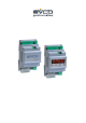
C-PRO MICRO HARDWARE MANUAL 1 Introduction The C-PRO MICRO family of programmable controllers is the ideal solution for refrigeration, ventilation and air conditioning applications in low complexity situations. Both in terms of regulation operations and the user interface, the controller software is fully programmable, in a simple and intuitive manner, thanks to the use of the UNI-PRO development environment. The C-PRO MICRO is made for installation on a DIN rail (see the figure below).
C-PRO MICRO HARDWARE MANUAL 2 Component and auxiliary network systems 2.
C-PRO MICRO HARDWARE MANUAL 2.
C-PRO MICRO HARDWARE MANUAL 3 Technical characteristics 3.1 Connections Power supply: The C-PRO MICRO is powered by a 12 V AC supply. It may also be powered by a 12 V DC supply; in this case, there is no option for controlling the fan cut-off modules. The maximum length of the power supply connecting cables is 1 m. Analogue input connections: The C-PRO MICRO has two analogue inputs for NTC probes and two for NTC probes or for 0/4-20 mA or 0-5V ratiometric transducers.
C-PRO MICRO HARDWARE MANUAL Connection with a remote expansion (or another CAN controller): The connection between C-PRO MICRO and the remote expansion (or other CAN controller) is made using a 2 way cable (better if weaved) plus possible ground. The maximum length of the connection cables to the remote controllers or expansions depend on the CAN port baud rate (see above section “User interface connections”).
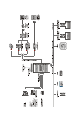
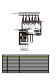
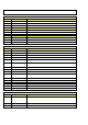
C-PRO MICRO HARDWARE MANUAL 3.2 The C-PRO MICRO wiring layout The C-PRO MICRO control unit wiring layout is shown below, with the meanings of the inputs and outputs given in the tables. C-PRO MICRO wiring diagram Connector 1: Output relay connection Conn. Abbrev. Description C1-1 DO1 Relay No.1, breaker normally open C1-2 COMMON DO1 Relay No. 1 - common C1-3 DO2 Relay No.2, breaker normally open C1-4 COMMON DO2 Relay No. 2 – common C1-5 DO3 Relay No.3, breaker normally open C1-6 COMMON DO3 Relay No.
C-PRO MICRO HARDWARE MANUAL Connector 2: Connection for the parameter upload/download key and/or output for RS485 module and/or controller flash download module Connector 3: Analogue output connector (optional, not available for open versions) Conn. Abbrev.
C-PRO MICRO HARDWARE MANUAL Connector 5: Connector for remote keypad and I/O expansion unit (CAN) Conn. Abbrev. Description C5-1 + Connector for the serial CAN+ connection C5-2 GND Ground reference connection C5-3 Connector for the serial CAN- Connection 3.3 C-PRO MICRO dimensions/installation The mechanical dimensions for the C-PRO MICRO are given below; the measurements are in mm (in). Recommendations for installation: - ensure that the operating conditions (operating temperature, humidity, etc.
C-PRO MICRO HARDWARE MANUAL To install the C-PRO MICRO, proceed as indicated in the figures (points 1 and 2). To remove the C-PRO MICRO, use a screw driver and proceed as indicated in the figures (points 3 and 4).
C-PRO MICRO HARDWARE MANUAL 3.
C-PRO MICRO HARDWARE MANUAL 3.
C-PRO MICRO HARDWARE MANUAL Fan analogue output UART1 TTL for RS485 serial port (Modbus) Type Voltage measurement range Voltage measurement accuracy Voltage measurement sensitivity Number Type Ratiometric 0 ÷ 5V ±50 mV 10 mV 1 EVCO impulse cut-off Number Type Physical layer Maximum baud rate Connector 1 UART TTL level signals 19200 bit/s 6 way AMP micro-match Please note: The same connector for the serial port is used for the parameter key and for the interface used for programming the microcontrolle
C-PRO MICRO HARDWARE MANUAL 4 The C-PRO MICRO user interface The display has 4 red-coloured digits (plus decimal points) and 16 icons of various colours; the keypad has 4 keys; the sealed case versions have neither display nor keypad and must be used in conjunction with a remote terminal.
C-PRO MICRO HARDWARE MANUAL Maintenance icon Alarm icon Icon 1 Icon 2 Icon 3 Icon 4 Heating element icon (air conditioning display) Compressor icon (refrigeration display) On-Off icon Keys Set / enter key Number of keys Normal pressing On-Off/esc key Pressed for approx. 3 seconds Normal pressing Up key Down key Esc+enter keys Up+down key Pressed for approx. 3 seconds Normal pressing Secondary function Normal pressing Secondary function Pressed for approx. 3 seconds Pressed for approx.
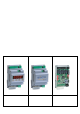
C-PRO MICRO HARDWARE MANUAL 5 C-PRO EXP MICRO I/O expansion units The C-PRO EXP MICRO I/O expansion units allow expansion of the controllers I/O capacity. There are two types of expansion unit, one sealed in a case with 4 DIN modules, and another open mounted on a base with 4 DIN modules.
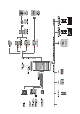
C-PRO MICRO HARDWARE MANUAL 5.1 The C-PRO EXP MICRO wiring layout (IntraBus version) The references to connecting cable lengths reported in chapter 3 are also valid for I/O expansion units. The C-PRO EXP MICRO expansion unit wiring layout is shown below, with the meanings of the inputs and outputs given in the tables. C-PRO EXP MICRO wiring diagram The C-PRO MICRO and C-PRO EXP MICRO power supplies must be galvanically isolated from one another. Connector 1: Output relay connection Conn. Abbrev.
C-PRO MICRO HARDWARE MANUAL Connector 2: Connector for low voltage signals Conn. Abbrev. Description C2-1 12 V AC (Power) Device power supply (12 V AC/DC) C2-2 Not connected Not connected C2-3 GND Common analogue and digital inputs C2-4 GND Common analogue and digital inputs C2-5 AI4 Analogue input No. 4 (for NTC probes or for 0/4-20 mA or 0-5 V transducers) C2-6 AI3 Analogue input No. 3 (for NTC probes or for 0/4-20 mA or 0-5 V transducers) C2-7 AI2 Analogue input No.
C-PRO MICRO HARDWARE MANUAL 5.2 C-PRO EXP MICRO dimensions/installation The mechanical dimensions for the C-PRO EXP MICRO are given below; the measurements are in mm (in). 6 Accessories 6.1 User terminals (IntraBus) User terminals allow the control units to be controlled remotely (display and commands). There are two interface types, one panel-mounted, the other wall-mounted. The interface is connected to the special (powered) serial connector of the C-PRO MICRO controllers.
C-PRO MICRO HARDWARE MANUAL 6.1.1 V LEDi dimensions and installation For panel installation, use the snap-on brackets provided Local panel-mounted interface dimensions Connections 3 2 1 GND 12Vdc DATA CI1 Local panel-mounted interface wiring diagram Connector CI1: Interface connector Conn. Abbrev.
C-PRO MICRO HARDWARE MANUAL The user interface has a 7 segment, 4 digit display (plus decimal point), 6 icons and the user mode is achieved using 4 keys. Display Number of digits Colour 4 Red Summer icon Winter icon Compressor icon Pump icon Defrost icon Alarm icon Colour Colour Colour Colour Colour Colour Red Red Red Red Red Red Keys Set / enter key Number of keys Normal pressing On-Off/esc key Pressed for approx.
C-PRO MICRO HARDWARE MANUAL 6.1.2 V WALL dimensions and installation For wall installation, use appropriate rawplugs and screws.
C-PRO MICRO HARDWARE MANUAL Connector CI2: Terminal connector powered by a separate transformer Conn. Abbrev.
C-PRO MICRO HARDWARE MANUAL The user interface has a 7 segment, 4 digit display (plus decimal point), 6 icons and the user mode is achieved using 4 keys. Display Number of digits Colour 4 Red Led L0 Led L1 Led L2 Led L3 Led L4 Led L5 Colour Colour Colour Colour Colour Colour Red Red Red Red Red Red Keys Set / enter key Number of keys Normal pressing On-Off/esc key Pressed for approx.
C-PRO MICRO HARDWARE MANUAL 6.2 Remote User interface (CAN) The user interfaces allow to install a display and keyboard remotely far from the controller . “V-VIEW” user interface (with a alfanumeric 4 x 20 characters LCD display) can be connected to the CAN port of the C-PRO MICRO controller. On request a graphic 240 x 128 pixel LCD display (V-GRAPH) user interface is also available . 6.2.
C-PRO MICRO HARDWARE MANUAL The following table summarizes the keyboard button meaning: BUTTONS MAIN FUNCTION SECONDARY FUNCTION Predefined as UP Predefined as DOWN Predefined as LEFT Predefined as RIGHT Predefined as ESC Stand-By command Predefined as ENTER 1° programming level command Programmable Alarm reset / identification Programmable Programmable Programmable Programmable Programmable + + + Controller configuration parameters command 2° programming level command 3° programming level comman
C-PRO MICRO HARDWARE MANUAL 6.2.1.2 V-VIEW wiring layout 6.2.1.3 V-VIEW specifications General specifications Safety standards references EN 60730-1 Purpose of the device Electronic control device connections To be integrated in equipment Plug-in terminal block 5mm pitch for conductors up to 2.
C-PRO MICRO HARDWARE MANUAL Type Serial CAN Communication Buzzer LCD Dispay Keyboard CAN V2.0B not optoisolated 2 wires + common, ISO 11898 standard 20K 50K 125K 500K Sconnectable terminals Physical Layer Baud rate (L max. = 10 m) Baud rate (L max. = 5 m) Baud rate (L max. = 2 m) Baud rate (L max. = 1 m) Connector Note: baud rate can be selected by parameter Note: The physical level of the CAN consists of a cable with twisted pair (both shielded and not shielded). The terminator's impedance is 120Ω.
C-PRO MICRO HARDWARE MANUAL 6.3 EVDFAN1 cut-off speed regulator The EVDFAN1 is a cut-off speed regulator for controlling single-phase fans (fans with maximum current absorption equal to 5 A). It is ideal for controlling the condensation/evaporation fans on a refrigeration control unit. EVDFAN1 The fan module is available as an open card version, and is mounted on a plastic base suitable for fitting on a DIN rail.
C-PRO MICRO HARDWARE MANUAL Terminals 1 and 2: Control input connector (Phoenix pull-out) Conn. Abbrev. Description 1 12 V DC 12 V DC power supply 2 AO1 Impulse cut-off input Terminals 3, 4, 5 and 6: Power connectors (FAST-ON) Conn. Abbrev. 3 LOAD Load 4 LOAD Load (Neutral) 5 LOAD Neutral 230 V AC 6 LOAD Live 230 V AC Description The cut-off module allows the control of single-phase fans with a maximum current equal to 5 A. The fan module live feed must be the same that supplies the controller.
C-PRO MICRO HARDWARE MANUAL 6.4 Supervision and monitoring accessories These modules allow the conversion of TTL signals to RS485 signals (with or without insulation) for supervision using the MODBUS protocol. The modules are connected to the special 6 way AMP micro-match connector on the controller; this connector is shared with the parameter programming key and the controller flash memory programming tools. 6.4.1 Non-insulated TTL/RS485 interface EVIF20TSX 6.4.
C-PRO MICRO HARDWARE MANUAL EVIF21TS7I connections Insulated interface wiring diagram Connector Conn. Abbrev.
C-PRO MICRO HARDWARE MANUAL 6.5 Programming accessories 6.5.1 EVKEY programming key The EVKEY programming key allows downloading/uploading parameters (even when the controller is not powered; in this case it is necessary to use the EVPS power supply). The key is connected to the special 6 way AMP micro-match connector, also used for supervision. EVKEY 6.5.
C-PRO MICRO HARDWARE MANUAL 7 CAN Connection C-PRO MICRO can be connected to other controllers, to expansion modules and to one or more user interfaces using either local or wide CAN serial port. The CAN bus uses the ISO 11898 standard, a balanced two-wire communication very similar to the RS 485 standard. Resistors with a recommended rating of 120-124 ohm have to be fitted at each end of the bus.
C-PRO MICRO HARDWARE MANUAL 7.1 Notes on the parameter of the controller relative to the CAN net configuration To log on the controller parameters configuration procedure relative to the analogic output act in the following way : Both for the remote or built-in user interface : 1. Ensure that the controller and the user interface are both switched on and no utilization is connected with the analogic output 2.
C-PRO MICRO HARDWARE MANUAL The main parameters of the CAN net are the following : • • • • “My Node” (represents the data sender ID ) “Network Node” (represents the receiver ID) Baud rate (represent the data transmissions speed; initially it can be useful to let this value set at “Auto”; in this way the device will try to connect a few time with different speed) Master (represents network operation) when instrument is set as master it checks device network to find Devices presence.
C-PRO MICRO HARDWARE MANUAL C-PRO MICRO hardware manual. Version 1.03 January 2009. Code 114CPRUHWE03. File 114CPRUHWE03.pdf. This document is the exclusive property of Evco, whereby any reproduction or distribution is strictly forbidden, unless expressly directly authorised by Evco. Evco assume no responsibility in relation to the characteristics, technical data and any possible errors reported in this document or deriving from the use of the same.
HEAD OFFICE Evco Via Mezzaterra 6, 32036 Sedico Belluno ITALY Tel: 0437-852468 Fax: 0437-83648 info@evco.it www.evco.it OVERSEAS OFFICES Control France 155 Rue Roger Salengro, 92370 Chaville Paris FRANCE Tel: 0033-1-41159740 Fax: 0033-1-41159739 control.france@wanadoo.fr Evco Latina Larrea, 390 San Isidoro, 1609 Buenos Aires ARGENTINA Tel: 0054-11-47351031 Tel: 0054-11-47351031 evcolatina@anykasrl.com.