PROGRAMMABLE CONTROLLER FOR CHILLER – HEAT PUMPS SINGLE-CIRCUIT 2 COMPRESSORS APPLICATION MANUAL CODE 144HPR0N0E00
C-PRO NANO HPR0 APPLICATION MANUAL Important Read these instructions carefully before installation and use and follow all recommendations regarding installation and for the electric connection; keep these instructions for future reference. The instrument must be disposed of according to local Standards regarding the collection of electric and electronic appliances.
C-PRO NANO HPR0 APPLICATION MANUAL Summary 1 Application and organisation of I/O ..................................................................................................................................................................... 4 I/O .............................................................................................................................................................................................................. 5 Connection lay out for C-PRO NANO INTRABUS .....
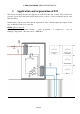
C-PRO NANO HPR0 APPLICATION MANUAL 1 Application and organisation of I/O The layouts attached describe the application (controlled unit and system). They indicate the presence of parts and components and not their precise position or other construction aspects of the units described. The I/O tables state the necessities and the organisation of the controller inputs and outputs for the type of unit and system to be controlled.
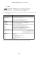
C-PRO NANO HPR0 APPLICATION MANUAL 1.1 I/O For HPR0 a C-PRO NANO (INTRAbus) must be used with the following features . Total analogical inputs: 4. Total digital inputs: 5 (*). Total digital outputs: 6. Total analogical outputs: 1 + 2 optionals (not present on this application). (*) Note: A total number of 7 digital inputs are used in this application for this purpose n°2 analogue inputs will be used as digital inputs. I/O Description Analogue Inputs A/I 1 Heating/cooling outlet / condit.
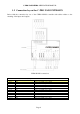
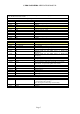
C-PRO NANO HPR0 APPLICATION MANUAL 1.2 Connection lay out for C-PRO NANO INTRABUS Below find the connection lay out of the C-PRO NANO controller with tables relative to the meaning of the inputs and outputs. C-PRO NANO connections Connector 1: Connection for the relay outputs Conn. Code C1-1 DO4 C1-2 DO3 C1-3 COMMON 1 C1-4 DO5 C1-5 DO2 C1-6 DO1 C1-7 COMMON 1 C1-8 COMMON 1 C1-9 COMMON DO5 C1-10 C1-11 DO6 Description Relay n.4 normally open contact Relay n.3 normally open contact Common relays n.
C-PRO NANO HPR0 APPLICATION MANUAL Connector 2: Connection for the upload/download parameters and/or output pen for RS485 module and/or controller flash download module Connector 3: Connector for the analogue output Conn.
C-PRO NANO HPR0 APPLICATION MANUAL 1.
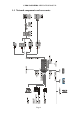
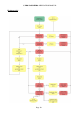
C-PRO NANO HPR0 APPLICATION MANUAL 2 Functioning Translation of terms used and notes Digital inputs Inter été/hiver = summer/winter switch (cooling/heating) Pressostat HP = HIGH pressure switch Pressostat BP = LOW pressure switch Controleur de débit d’eau circuit chauffage = OUTLET circuit flow switch Controleur de débit d’eau circuit chauffage = GEOTHERMIC circuit flow switch Thermostat d’ambiance = ROOM thermostat (inserts compressor 1) Thermostat d’ambiance = EXTERNAL thermostat (inserts compressor 2)
C-PRO NANO HPR0 APPLICATION MANUAL Heating mode 1 Page 10
C-PRO NANO HPR0 APPLICATION MANUAL Heating mode 2 Page 11
C-PRO NANO HPR0 APPLICATION MANUAL Cooling mode 1 Page 12
C-PRO NANO HPR0 APPLICATION MANUAL Cooling mode 2 N.B.
C-PRO NANO HPR0 APPLICATION MANUAL 3 User Interface 3.1 Display and keyboard The following interface is envisioned for the application: ⋅ A 4 display interface with 7 Built-In segments with icons ⋅ With 4 keys with navigation/editing the pages and they differ for display The following icons are also used: - Summer icon: identifies the cooling functioning mode (summer - chiller): if the heat regulation requests, it is on in fixed mode, otherwise it is off.
C-PRO NANO HPR0 APPLICATION MANUAL 3.2 List of pages This paragraph presents the main pages and menus found in the application. As shown previously, the main menu is divided into 3 levels: user, maintenance - installer and manufacturer.
C-PRO NANO HPR0 APPLICATION MANUAL 3.5 Main ON page The main page displays the temperature of the outlet water and the relative icons on at that moment. By pressing the DOWN key for about 2 seconds from this page, enter MENU. From MENU, by pressing the ESC key, go back to the main page. 3.6 Main Menu The main menu does not have a level and is the access point for all other system menus.
C-PRO NANO HPR0 APPLICATION MANUAL 3.9 Maintenance technician - Installer menu The maintenance technician - installer level password or higher must be entered in order to display/modify the parameters present in this branch.
C-PRO NANO HPR0 APPLICATION MANUAL 3.11 Project and Firmware Versions Press the UP+DOWN keys at the same time for about 2 seconds and successively press ENTER on the InFo label. The information regarding the versions of the project and the controller firmware are displayed in sequence, precisely: Project Number <-> Project Version <-> Project Revision <-> Firmware Number <-> Firmware Version <-> Firmware Revision Use the UP and DOWN keys to scroll the information.
C-PRO NANO HPR0 APPLICATION MANUAL 4 List of Parameters The same parameters organisation used for c-pro CHILL can be maintained. For the parameters and functions of the c-pro HPR0 application, see the following table. As an example, the codes used with CHIL have been maintained (that will appear on the LED display), but which will be “re-organised” regarding numbering depending on this new application.
C-PRO NANO HPR0 APPLICATION MANUAL PP06 PP07 PP08 PA01 PA02 PA03 PA04 off of the unit and pumps switch-off Pumps switch-on delay pumps switch-off delay (winter mode) pumps switch-off delay (summer mode) Reset the factory parameters default PSd4 Manufacturer level password PH06 PH16 PH17 PH18 PH19 PH20 PH21 PH43 PH44 PH52 1 1 1 Flow switches alarm delay from pumps 30 1 switch-on Flow switch alarm delay 10 1 Low pressure alarm delay after start-up of the 240 1 first compressor Probe error del
C-PRO NANO HPR0 APPLICATION MANUAL HARDWARE CONFIGURATION Those eventually necessary (to be defined in the design phase) 5 Controls and regulations 5.1 Machine state The unit is switched-on/off using the relative On/Off key : Switch-on - press the relative key for 2 seconds: if all of the other conditions enabled are present, the machine goes to “ON”. Switch-off - press the relative key for 2 seconds: the machine goes to “OFF” mode.
C-PRO NANO HPR0 APPLICATION MANUAL 5.3 Regulation and management of the compressors The controller can manage up to a maximum of 2 compressors. Digital outputs for switch-on/off and protection inputs (pressure switches) are associated with every compressor. Switch-on/off is defined depending on the set/outlet temperature, some timing and request of the room thermostat and the indoor thermostat. The compressor switch-on control takes place on the basis of the outlet temperature AI1.
C-PRO NANO HPR0 APPLICATION MANUAL 5.4 Compressors status The compressor has one functioning state associated, which can be seen via the relative LED or in the states mask from the main menu. The compressor assumes the following states: - On: “On” appears on the state mask Switch-on stand-by: the compressor is in stand-by due to the switch-on protection times.
C-PRO NANO HPR0 APPLICATION MANUAL 5.7 Management of the geothermic circulation pumps and heating/cooling The application can manage the unit and system pumps. A safety digital input and a digital output for switch-on/off can be associated at every use. 5.8 Pump status The pumps are each controlled by a dedicated digital output (see I/O table). Functioning takes place on call of the ON-OFF thermostats (EXT and/or INT) and/or outlet temperature.
C-PRO NANO HPR0 APPLICATION MANUAL 5.10 Flow switches management The 2 unit flow switches are managed separately: heating/air conditioning circuit, geothermic circuit, but the setting of the “Flow switches alarm delay” is unique for the two flow switches. On expiry of the Flow switches alarm delay time, if the contact signals no flow, the alarm is given immediately, stopping the pump and preventing compressor switch-on.
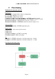
C-PRO NANO HPR0 APPLICATION MANUAL 6 Programming The instrument can be programmed from front key or using the programming key. Programming key It is possible to save the value of all system parameters in the programming key and allow copying into one or more compatible instruments. The saving or reset operation can only be performed with machine OFF, by connecting the key to the programming container.
C-PRO NANO HPR0 APPLICATION MANUAL 7 Alarms All alarms are envisioned with manual reset from controller front key. In the event of an alarm: ⋅ The alarm icon starts to flash By pressing the ENTER key from the “Alar” menu, the code of the first active alarm is displayed. Once the conditions that caused the alarm in the unit have been eliminated, the alarm can be reset manually. To perform this operation: ⋅ be positioned on the page of the alarm to be reset ⋅ hold the ENTER key down for about 2 seconds.
C-PRO NANO HPR0 APPLICATION MANUAL Page 28
C-PRO NANO HPR0 APPLICATION MANUAL Application manual C-PRO NANO HPR0 Version 1.0 of September 2010 Code CODE 144HPR0N0E00. This publication is exclusive property of Evco, which prohibits reproduction and distribution,, unless expressly authorised by Evco itself. Evco does not assume any liability regarding the features, technical data and possible errors in this document or deriving from use of the same. Evco cannot be held responsible for any damage caused by the failure to comply with the warnings.
OFFICES Evco Via Mezzaterra 6, 32036 Sedico Belluno ITALIA Tel. 0437-852468 Fax 0437-83648 info@evco.it www.evco.it OVERSEES BRANCHES Control France 155 Rue Roger Salengro, 92370 Chaville Paris FRANCE Tel. 0033-1-41159740 Fax 0033-1-41159739 control.france@wanadoo.fr Evco Latina Larrea, 390 San Isidoro, 1609 Buenos Aires ARGENTINA Tel. 0054-11-47351031 Fax 0054-11-47351031 evcolatina@anykasrl.com.ar Evco Pacific 59 Premier Drive Campbellfield, 3061, Victoria Melbourne, AUSTRALIA Tel.