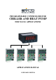
PROGRAMMABLE CONTROLLERS FOR CHILLER AND HEAT PUMP FOR NAVAL APPLICATIONS APPLICATION MANUAL CODE 144NAV0NUE16
C-PRO NANO AND MICRO NAV APPLICATION MANUAL Important Read these instructions carefully before installation and use and follow all recommendations regarding installation and for the electric connection; keep these instructions for future reference. The instrument must be disposed of according to local Standards regarding the collection of electric and electronic appliances.
C-PRO NANO AND MICRO NAV APPLICATION MANUAL Summary 1 Generalities .......................................................................................................................................................................................................... 4 Description................................................................................................................................................................................................. 4 Applications...................
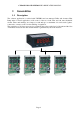
C-PRO NANO AND MICRO NAV APPLICATION MANUAL 1 Generalities 1.1 Description The software application is realised with UNI-PRO and can manage Chiller and air-water Heat Pump units for naval applications, with control of the two fresh water and salt water hydraulic circuits. These units manage one compressor each and up to a maximum of 4 can be used together, connected to a master control for the enabling of regulation.
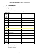
C-PRO NANO AND MICRO NAV APPLICATION MANUAL 2 Applications The following types of controllers can be managed: 2.1 Master (nano) Master for chiller + single circuit water -water heat pump units. Analogue Inputs AI 1 (NTC) AI 2 (NTC) AI 3 (NTC) AI 4 (NTC) Digital Inputs DI 1 - DI 2 Change-Over DI 3 - DI 4 - DI 5 - Summer/Winter Digital Outputs DO 1 - DO 2 - DO 3 Fresh water pump DO 4 General alarm DO 5 - DO 6 - Analogue outputs AO 1 (PWM) AO 2 (0..10V) AO 3 (0..
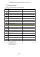
C-PRO NANO AND MICRO NAV APPLICATION MANUAL 2.2 Slave unit (micro) Chiller + single circuit water -water heat pump unit.
C-PRO NANO AND MICRO NAV APPLICATION MANUAL 2.
C-PRO NANO AND MICRO NAV APPLICATION MANUAL 2.
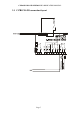
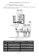
C-PRO NANO AND MICRO NAV APPLICATION MANUAL 2.5 C-PRO NANO electric connections Below find a representation of the connection layout of the C-PRO NANO controller with tables relative to the meaning of the inputs and outputs. C-PRO NANO connections Connector 1: Connection for the relay outputs Conn. Code C1-1 DO4 C1-2 DO3 C1-3 COMMON1 C1-4 DO5 C1-5 DO2 C1-6 DO1 C1-7 COMMON1 C1-8 COMMON1 C1-9 COMMON DO5 C1-10 C1-11 DO6 Description Relay n.4 normally open contact Relay n.
C-PRO NANO AND MICRO NAV APPLICATION MANUAL Connector 2: Connection for the upload/download parameters key and/or output for RS485 module and/or download flash module of the controller Connector 3: Connector for analogue output Conn.
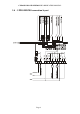
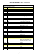
C-PRO NANO AND MICRO NAV APPLICATION MANUAL 2.6 C-PRO MICRO electric connections Below find a representation of the connection layout of the C-PRO MICRO controller with tables relative to the meaning of the inputs and outputs. C-PRO MICRO connections Connector 1: Connection for the relay outputs Conn. Code C1-1 DO1 C1-2 COMMON DO1 C1-3 DO2 C1-4 COMMON DO2 C1-5 DO3 C1-6 COMMON DO3 C1-7 DO4 C1-8 COMMON DO4, DO5 C1-9 DO5 C1-11 DO6 C1-12 COMMON DO6 Description Relay n.1 normally open contact Common relay n.
C-PRO NANO AND MICRO NAV APPLICATION MANUAL Connector 2: Connection for the upload/download parameters key and/or output for RS485 module and/or download flash module of the controller Connector 3: Connector for analogue output (optional, not available in the day versions) Conn.
C-PRO NANO AND MICRO NAV APPLICATION MANUAL 2.
C-PRO NANO AND MICRO NAV APPLICATION MANUAL 2.
C-PRO NANO AND MICRO NAV APPLICATION MANUAL 3 USER INTERFACE 3.1 Display and keyboard The application is made up from two parts, 1 master and n slave (maximum 4). The slave units are blind (day version), therefore without display and without keys: the information can be displayed and parameters set directly by the master. The master controller has a user interface with 4 displays with 7 segments and 16 icons.
C-PRO NANO AND MICRO NAV APPLICATION MANUAL - Salt water pump icon: identifies the status of the selected unit pump. o UNIT: If on the pump is functioning, if flashing fast it signals that timing is active. - Alarm icon: Identifies the presence or not of alarms. If on, alarms are present in at least one of the units, otherwise it remains off. Flashing signals the presence of a new alarm not yet displayed. The icon flashes if there are alarms when the machine is off.
C-PRO NANO AND MICRO NAV APPLICATION MANUAL 3.2 List of the pages This paragraph presents the main pages and the menus found in the application. Main page The main screen is different according whether the status of the machine is of or on: - if the machine is off, the OFF wording is shown - if the machine is on, the average of the fresh water input temperature values of the units connected to the master is displayed. If all of the units are disconnected, “----“ appears.
C-PRO NANO AND MICRO NAV APPLICATION MANUAL • On: Unit that is regulating PUMP: status of the salt water pump (OFF, tOn, On) COMp: status of the compressor (OFF, tOn, On, tOFF) The flashing numerical LED, within this menu, will remain on indicating the node that is being monitored.
C-PRO NANO AND MICRO NAV APPLICATION MANUAL 4 List of parameters Below find the list of all parameters managed by the application. A brief description, the range of acceptable values, unit of measurement, the default value proposed and the menu in which it is found is supplied for every parameter. The menus are structured following this logic: ⋅ ⋅ ⋅ LEV1: user menu LEV2 : installer menu LEV3 : administrator menu 4.
C-PRO NANO AND MICRO NAV APPLICATION MANUAL tFLo tCoM SET1 diF1 SET2 diF2 SET3 diF3 SET4 diF4 dAL1 EAL1 dAL2 dAL3 EAL3 dAL4 tAL4 nDeL tDeL dSF tSF nUM UdM Addr bAud Equal StoP PDI1 Flow alarm delay during normal functioning Communication alarm delay Summer condensation high temperature alarm set point (chiller) Summer condensation high temperature alarm differential (chiller) Summer evaporation low temperature alarm set point (chiller) Summer evaporation low temperature alarm differential (chiller) Winter
C-PRO NANO AND MICRO NAV APPLICATION MANUAL PDI2 PDI3 PDI4 PDI5 Icon PSd1 PSd2 PSd3 CAn 1: Normally closed NC Sets the digital input logic used for the change over: 0: Normally open NO 1: Normally closed NC Sets the digital input logic used for the high pressure switch: 0: Normally open NO 1: Normally closed NC Sets the digital input logic used for the low pressure switch: 0: Normally open NO 1: Normally closed NC Sets the digital input logic used for regulation consent: 0: Normally open NO 1: Normal
C-PRO NANO AND MICRO NAV APPLICATION MANUAL 5 CONFIGURATIONS 5.1 Setting number of the slaves To set the number of the slaves that will be connected to the master, hold the ENTER key for about 2 seconds and then access the main menu. Enter the administrator menu and modify the nUM parameter. 5.
C-PRO NANO AND MICRO NAV APPLICATION MANUAL 6 REGULATIONS 6.1 Machine status Procedure doe switch-on/off of the unit using the relative On/Off key: Switch-on - press the relative key for about 2 seconds: the machine goes to "ON" and displays the average temperature of the input fresh water of the connected units. Switch-off - press the relative key for about 2 seconds: the machine goes to "OFF". The machine On/Off key is the ESC key.
C-PRO NANO AND MICRO NAV APPLICATION MANUAL 6.4 Calculating steps The master acquires the fresh water input temperature of the slave units and calculate the enabling steps on the basis of the average input temperature and the BAnd regulation band. The regulation band is divided into the same amount of steps as the slave units connected to the master, in this way the master decides how many chillers to activate.
C-PRO NANO AND MICRO NAV APPLICATION MANUAL 6.6 Regulation of the compressor With consent from the master, the compressor switch-on command takes place on the basis of the AI2 output fresh water temperature. The following figure shows the behaviour of the regulation in the case of summed functioning (chiller). On the basis of the output temperature value, the regulation request s the switch-on of the compressor. In this regulation, the band is moved totally above the set-point.
C-PRO NANO AND MICRO NAV APPLICATION MANUAL 6.6.2 Protection times Below find a list of all times relative to management of the compressors These times are used to protect the mechanical means from the various peaks to which they are subjected. tOn = Compressors minimum switch-on time. Once activated, the compressor will remain on for this time before being able to be switched-off. tOFF = Compressors minimum switch-off time.
C-PRO NANO AND MICRO NAV APPLICATION MANUAL 6.7 Management of fresh water and salt water The fresh water pump is switched-on when the machine is switched-on and remain on always during all functioning. Only for machine switch-off or for the change-over it is switched-off with a delay t4. The flow input determines the correct circulation of the fresh water in the circuit, stopping the machine the absence of flow is detected. From the enabling of the regulation a time of t1 before checking the flow input.
C-PRO NANO AND MICRO NAV APPLICATION MANUAL 6.8 Condenser and evaporator alarms The following controls check the temperature of the gas in the condensation and evaporation heat exchangers and detect the alarm conditions, which determine compressor block. The alarms are active also with the compressor off. 6.8.1 Summer condensation high temperature alarm The following figure shows the behaviour on the condenser in the case of summed functioning (chiller).
C-PRO NANO AND MICRO NAV APPLICATION MANUAL AT3 ON SET3 Gas temperature at condenser input SET3 + 6.8.4 Winter evaporation high temperature alarm The following figure shows the behaviour on the evaporator in the case of winter functioning (heat pump). On the basis of the output gas temperature at the AI4 condenser, the alarm is activated over the set-point and deactivated after a differential below the set-point. AT4 ON SET4 + SET4 at evaporator output 6.
C-PRO NANO AND MICRO NAV APPLICATION MANUAL 6.10 DELTA alarms These alarms allow to check the correct machine functioning, monitoring the respect of several temperature values with the compressor on. The alarm condition is delayed on start-up of the compressor by a time (tDEL parameter, default 10sec). 6.10.
C-PRO NANO AND MICRO NAV APPLICATION MANUAL 7 DIAGNOSTICS The application can manage a series of alarm relative to compressors, fans, circuits and system functionality. On the basis of the various types of alarm a reset can be configured (if manual or automatic), any signal delay and the actions to be performed in the specific case. The display alarm icon flashes when one or more alarms are active.
C-PRO NANO AND MICRO NAV APPLICATION MANUAL 7.2 Alarms Table Below is a list of all alarms managed by the application. The order of presentation is the same as the order with which the alarms are displayed when active. The alarms code as the number of the unit where the alarm is occurring as the last number (in the table indicated by n) Code Typ e Alarm description COMn Communication error with the unit n ES1n Fresh water input temp. probe broken or disconnected error ES2n Fresh water output temp.
C-PRO NANO AND MICRO NAV APPLICATION MANUAL AL1n DELTA 1 alarm AL2n DELTA 2 alarm AL3n DELTA 3 alarm AL4n DELTA 4 alarm ASFn Phase sequence alarm Auto /Ma nu Auto /Ma nu Auto /Ma nu Auto /Ma nu Man u Compressor OFF Salt water pump OFF Compressor OFF Salt water pump OFF Compressor OFF Salt water pump OFF Compressor OFF Salt water pump OFF Compressor OFF Salt water pump OFF Compressor startup delay. In summer only Compressor startup delay. In summer only Compressor startup delay.
C-PRO NANO AND MICRO NAV APPLICATION MANUAL 8 List of Modbus variables To be realised on Customer request Page 34
C-PRO NANO AND MICRO NAV APPLICATION MANUAL Application manual C-PRO NANO AND MICRO NAV Version 1.6 of September 2010 Code 144NAV0NUE16. This publication is exclusive property of Evco, which prohibits reproduction and distribution,, unless expressly authorised by Evco itself. Evco does not assume any liability regarding the features, technical data and possible errors in this document or deriving from use of the same.
OFFICES Evco Via Mezzaterra 6, 32036 Sedico Belluno ITALIA Tel. 0437-852468 Fax 0437-83648 info@evco.it www.evco.it OVERSEES BRANCHES Control France 155 Rue Roger Salengro, 92370 Chaville Paris FRANCE Tel. 0033-1-41159740 Fax 0033-1-41159739 control.france@wanadoo.fr Evco Latina Larrea, 390 San Isidoro, 1609 Buenos Aires ARGENTINA Tel. 0054-11-47351031 Fax 0054-11-47351031 evcolatina@anykasrl.com.ar Evco Pacific 59 Premier Drive Campbellfield, 3061, Victoria Melbourne, AUSTRALIA Tel.