
Instruction Manual

C-PRO NANO RACK AND C-PRO MICRO RACK APPLICATION MANUAL
Page
17
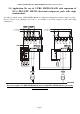
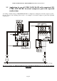
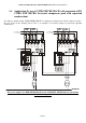
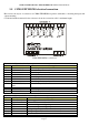
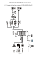
2.8 C-PRO EXP MICRO electrical connection
Here follows the layout of connection of C-PRO EXP MICRO expansion with tables concerning the inputs and
outputs meaning.
Consult the hardware manual for the references about the connection cables’ maximum lenght.
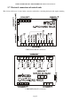
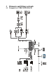
C-PRO EXP MICRO connections
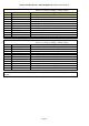
Connector 1: Connection for relay outputs
Conn. Abbreviation Description
C1-1 DO7 Normally open contact relay n.7
C1-2 COMMON DO7 Common relay n.7
C1-3 DO8 Normally open contact relay n.8
C1-4 COMMON DO8 C Common relay n.8
C1-5 DO9 Normally open contact relay n.9
C1-6 COMMON DO9 Common relay n.9
C1-7 DO10 Normally open contact relay n.10
C1-8 COMMON DO10,
DO11
Common relay n.10, 11
C1-9 DO11 Normally open contact relay n.11
C1-11 DO12 Normally open contact relay n.12
C1-12 COMMON DO12 Common relay n.12
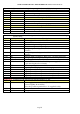
Connector 2: Connector for low tension signals
Conn. Abbreviation Description
C2-1 12Vac (Power) Power supply of the tool (12Vac/dc)
C2-2 Not connected Not connected
C2-3 GND Common analogue and digital inputs
C2-4 GND Common analogue and digital inputs
C2-5 AI8 Analogue input n.8 (for 4-20 mA transductors)
C2-6 AI7 Analogue input n.7 (for 4-20 mA transductors)
C2-7 Not connected Not connected
C2-8 Not connected Not connected