EVCO S.p.A. EVXV 800 range | Installer manual ver. 1.2 | Code 144XV800E124 EVXV 800 range Controllers for blast chillers (integrated into the unit) ENGLISH INSTALLER MANUAL ver. 1.
EVCO S.p.A. EVXV 800 range | Installer manual ver. 1.2 | Code 144XV800E124 Important Important Read this document thoroughly before installation and before use of the device and follow all recommendations; keep this document with the device for future consultation. The following symbols support reading of the document: indicates a suggestion indicates a warning The device must be disposed of in compliance with local Standards regarding the collection of electric and electronic equipment.
EVCO S.p.A. EVXV 800 range | Installer manual ver. 1.2 | Code 144XV800E124 Index 1 INTRODUCTION ...................................................................................................................................5 1.1 Introduction ........................................................................................................................................5 1.2 Summary table of the main features and the models available ..........................................................
EVCO S.p.A. EVXV 800 range | Installer manual ver. 1.2 | Code 144XV800E124 9.3 Restoring the factory settings .............................................................................................................. 33 9.4 List of configuration parameters ........................................................................................................... 33 10 SIGNALS AND INDICATIONS ..........................................................................................................
EVCO S.p.A. EVXV 800 range | Installer manual ver. 1.2 | Code 144XV800E124 1 INTRODUCTION 1.1 Introduction The EVXV 800 line is a range of digital controllers studied to manage temperature-controlled blast chillers, which can be mechanically and aesthetically integrated into the unit. The range is made up from 4 devices: EVXV802, EVXV812, EVXV805 and EVXV815.
EVCO S.p.A. EVXV 800 range | Installer manual ver. 1.2 | Code 144XV800E124 Via a serial interface (to be ordered separately), it is also possible to connect the controller to the Parameters Manager set-up software system, to the monitoring and surveillance system of the RICS plants or to the data recording device, to download the recorded data (via USB), to upload and download EVUSBREC01 configuration parameters.
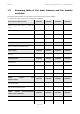
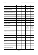
EVCO S.p.A. EVXV 800 range | Installer manual ver. 1.2 | Code 144XV800E124 1.2 Summary table of the main features and the models available The following table illustrates the main features of the devices and the models available. “/“ indicates the feature can be set via a configuration parameter.
EVCO S.p.A. EVXV 800 range | Installer manual ver. 1.
EVCO S.p.A. EVXV 800 range | Installer manual ver. 1.2 | Code 144XV800E124 “HACCP” function • • "keyboard lock" function • • • • configuration parameters access password • • • • restoring the factory settings • • • • Codes EVXV802 EVXV812 EVXV805 EVXV815 codes EVXV802P7 EVXV812P7 EVXV805P7 EVXV815P7 For further information, see chapter 14 "TECHNICAL DATA"; for other models contact the EVCO sales network.
EVCO S.p.A. EVXV 800 range | Installer manual ver. 1.2 | Code 144XV800E124 2 DESCRIPTION 2.1 Description of EVXV802 and EVXV812 The following drawing illustrates the aspect of EVXV802 and EVXV812 The following table illustrates the meaning of EVXV802 and EVXV812. parts.
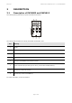
EVCO S.p.A. 2.2 EVXV 800 range | Installer manual ver. 1.2 | Code 144XV800E124 Description of EVXV805 and EVXV815 The following drawing illustrates the aspect of EVXV805 and EVXV815 The following table illustrates the meaning of EVXV805 and EVXV815 parts.
EVCO S.p.A. EVXV 800 range | Installer manual ver. 1.2 | Code 144XV800E124 3 DIMENSIONS AND INSTALLATION 3.1 Dimensions of EVXV802 and EVXV812 The following drawing illustrates EVXV802 and EVXV812 dimensions; these are expressed in mm (in). 3.2 Dimensions of EVXV805 and EVXV815 The following drawing illustrates EVXV805 and EVXV815 dimensions; these are expressed in mm (in).
EVCO S.p.A. 3.3 EVXV 800 range | Installer manual ver. 1.2 | Code 144XV800E124 Installation Back panel via M3 studs 3.4 - Installation warnings make sure that the device work conditions (temperature of use, humidity, etc.) lie within the limits indicated; see chapter 14 "TECHNICAL DATA". - do not install the device near to any heat sources (heating elements, hot air ducts etc.), equipment containing powerful magnets (large diffusers, etc.
EVCO S.p.A. EVXV 800 range | Installer manual ver. 1.2 | Code 144XV800E124 4 ELECTRIC CONNECTION 4.1 EVXV802 and EVXV812 electric connection The following drawing illustrates the EVXV802 and EVXV812 electric connection. The function of the fourth input depends on parameter 5, as follows: - high pressure input (digital input, P5 = 0) - condenser probe (analogue input, P5 = 1, pre-defined setting). For the settings relative to the parameters, see chapter 9 “CONFIGURATION”.
EVCO S.p.A. 4.2 EVXV 800 range | Installer manual ver. 1.2 | Code 144XV800E124 EVXV805 and EVXV815 electric connection The following drawing illustrates the EVXV805 and EVXV815 electric connection. The function of the fourth input depends on parameter 5, as follows: - high pressure input (digital input, P5 = 0) - condenser probe (analogue input, P5 = 1, pre-defined setting). For the settings relative to the parameters, see chapter 9 “CONFIGURATION”.
EVCO S.p.A. 4.3 EVXV 800 range | Installer manual ver. 1.
EVCO S.p.A. EVXV 800 range | Installer manual ver. 1.2 | Code 144XV800E124 5 USER INTERFACE 5.1 Foreword The following operating status’ exist: - the “off” status (the device is not powered) - the “stand-by” status (the device is powered and is off) - the “on” status (the device is powered, is on and is in stand-by for the start-up of an operating cycle) - the “run” status (the device is powered, is on and an operating cycle is in progress).
EVCO S.p.A. EVXV 800 range | Installer manual ver. 1.2 | Code 144XV800E124 Operate as follows to exit the procedure: 5. 6. Press and release the BLAST CHILLING key or do not operate for 15 s: the display will show “Pb1” again. Press and release the UP or DOWN key until the display shows the magnitude indicated in paragraph 5.3 "The display" or do not operate for 60 s. 5.5 Display of the temperature detected by the needle probe Operate as follows: 1.
EVCO S.p.A. 5.8 EVXV 800 range | Installer manual ver. 1.2 | Code 144XV800E124 Defrosting activation in manual mode Operate as follows: 1. Make sure the device is in the "on" status or a storage is in progress. 2. Make sure that the keyboard is not locked and that no procedure is in progress. 3.1 In models EVXV802 and EVXV812, hold the UP key down for 4 s: the 3.2 In models EVXV805 and EVXV815, hold the DEFROSTING key down for 4 s: the LED will switch on. LED will switch on.
EVCO S.p.A. 5.11 EVXV 800 range | Installer manual ver. 1.2 | Code 144XV800E124 Silencing the buzzer Operate as follows: 1. Make sure no procedures are in progress 2. Press and release the key.
EVCO S.p.A. EVXV 800 range | Installer manual ver. 1.2 | Code 144XV800E124 6 OPERATION 6.1 Foreword The devices can manage the following operating cycles: - blast chilling and storage - hard blast chilling and storage - deep freezing and storage - soft deep freezing and storage. For further information, see the next paragraphs. Every operating cycle can be preceded by pre-cooling; see paragraph 6.6 "Pre-cooling".
EVCO S.p.A. EVXV 800 range | Installer manual ver. 1.2 | Code 144XV800E124 The maximum blast chilling duration count is started on condition that the temperature detected by the needle probe is below that established with parameter r15. 5.2 If the test is not completed successfully, the cycle will be started with timed-control. During blast chilling, the display shows the residual time of the blast chilling duration and the LED is on. To modify the residual time, operate as indicated: 5.2.
EVCO S.p.A. EVXV 800 range | Installer manual ver. 1.2 | Code 144XV800E124 4. Press and release the HARD/SOFT key: the HARD LED will flash. 5.1 If parameter r19 is set at 0, the display will show the work set-point during blast chilling; this value can also be set via parameter r7. If parameter r21 has value 1 and it has been decided to start the cycle with timed-control, the display will show the duration of time-controlled blast chilling; this value can also be set via parameter r1. 5.
EVCO S.p.A. EVXV 800 range | Installer manual ver. 1.2 | Code 144XV800E124 To display the cabinet temperature, press and release the BLAST CHILLING key; to restore the normal display, press and release the BLAST CHILLING key again or do not operate for 15 s.
EVCO S.p.A. EVXV 800 range | Installer manual ver. 1.2 | Code 144XV800E124 During deep freezing, the display shows the residual time of the deep freezing duration and the LED is on. To modify the residual time, operate as indicated: 5.2.1 Press and release the UP or DOWN key again to modify the time value: the display will flash. 5.2.2 Do not operate for 4 s: the display will stop flashing and remain on permanently.
EVCO S.p.A. 5.1 EVXV 800 range | Installer manual ver. 1.2 | Code 144XV800E124 If parameter r19 is set at 0, the display will show the work set-point during deep freezing; this value can also be set via parameter r8. If parameter r21 has value 1 and it has been decided to start the cycle with timed-control, the display will show the duration of time-controlled deep freezing; this value can also be set via parameter r2. 5.
EVCO S.p.A. EVXV 800 range | Installer manual ver. 1.2 | Code 144XV800E124 To display the cabinet temperature, press and release the DEEP FREEZING key; to restore the normal display, press and release the DEEP FREEZING key again or do not operate for 15 s.
EVCO S.p.A. EVXV 800 range | Installer manual ver. 1.2 | Code 144XV800E124 To start the temperature-controlled cycle, press the BLAST CHILLING key or the DEEP FREEZING key. After 1 min from the signal that the test has not been completed successfully without having operated, the cycle is started with time control. If parameter r17 is set at 0.0, the test will not be carried out (neither first nor second phase). 6.
EVCO S.p.A. 7 EVXV 800 range | Installer manual ver. 1.2 | Code 144XV800E124 “HACCP” FUNCTION (EVXV812 AND EVXV815 MODELS ONLY) 7.1 Foreword Using the “HACCP” function, it is possible to memorise up to 9 events for each of the 3 HACCP alarms, after which the most recent event overwrites the oldest. The following table illustrates the information relative to the HACCP alarms, which the device can memorise.
EVCO S.p.A. EVXV 800 range | Installer manual ver. 1.2 | Code 144XV800E124 Inf. Meaning 8.0 the critical value is 8.0 °C/8 °F StA the display is about to show the date and time the alarm occurred y11 the alarm occurred in 2011 (continue...) n03 the alarm occurred in in the month of March (continue...) d26 the alarm occurred on 26 March 2011 h16 the alarm occurred at 16:00 (continue...
EVCO S.p.A. EVXV 800 range | Installer manual ver. 1.2 | Code 144XV800E124 8 COMPRESSOR OPERATING HOURS COUNT 8.1 Displaying compressor operating hours Operate as follows: 1. Make sure that the keyboard is not locked and that no procedure is in progress. 2. Hold the DOWN key down for 1 s: the display will show the first label available. 3. Press and release the UP or DOWN key to select “CH”. 4. Press and release the BLAST CHILLING key: the display will show the compressor operating hours.
EVCO S.p.A. EVXV 800 range | Installer manual ver. 1.2 | Code 144XV800E124 9 CONFIGURATION 9.1 Setting the real date and time (in EVXV812 and EVXV815 models only) Operate as follows: 1. Make sure that the keyboard is not locked and that no procedure is in progress. 2. Hold the DOWN key for 1 s: the display will show the first label available. 3. Press and release the UP or DOWN key to select “rtc”. Operate as follows to set the year: 4.
EVCO S.p.A. EVXV 800 range | Installer manual ver. 1.2 | Code 144XV800E124 9. Press and release the UP or DOWN key within 15 s to modify the parameter value: 10. Press and release the BLAST CHILLING key or do not operate for 15 s: the display will show the parameter label again. Operate as follows to exit the procedure: 11. Hold the UP and DOWN key for 4 s or do not operate for 60 s. The display will show the magnitude indicated in paragraph 5.3 "The display".
EVCO S.p.A. EVXV 800 range | Installer manual ver. 1.2 | Code 144XV800E124 EVXV802 EVXV805 EVXV812 EVXV815 °C/°F (1) 0.0 0.0 cabinet probe offset 25.0 °C/°F (1) 0.0 0.0 needle probe offset -25.0 25.0 °C/°F (1) 0.0 0.0 evaporator probe offset -25.0 25.0 °C/°F (1) 0.0 0.0 condenser probe offset Par. Min. Max. Unit CA1 -25.0 25.0 CA2 -25.
EVCO S.p.A. EVXV 800 range | Installer manual ver. 1.2 | Code 144XV800E124 temperature-controlled blast chilling end time temperature; also end temperature of the r3 -50.0 99.0 °C/°F (1) 3.0 3.0 temperature-controlled soft deep freezing phase (temperature detected by the needle probe); also see parameter r5 temperature-controlled r4 -50.0 99.0 °C/°F (1) -18.0 -18.
EVCO S.p.A. EVXV 800 range | Installer manual ver. 1.2 | Code 144XV800E124 duration of the time-controlled hard blast chilling phase (intended as a percentage of r14 10 100 % 60 60 the value established with parameter r1); also duration of the time-controlled soft deep freezing phase (intended as a percentage of the value established with parameter r2) temperature below which the count of the maximum r15 -50.0 99.0 °C/°F (1) 65.0 65.
EVCO S.p.A. EVXV 800 range | Installer manual ver. 1.
EVCO S.p.A. C3 EVXV 800 range | Installer manual ver. 1.2 | Code 144XV800E124 0 240 s 0 0 compressor switch-on minimum duration duration of compressor switch-off during the C4 0 240 min 10 10 cabinet probe error (“Pr1” code) that occurs during storage; see also parameter C5 duration of compressor switch-on during the C5 0 240 min 10 10 cabinet probe error (“Pr1” code) that occurs during post blast chilling storage; also see parameter C4 condenser C6 0 199.0 °C/°F (1) 80.0 80.
EVCO S.p.A. EVXV 800 range | Installer manual ver. 1.
EVCO S.p.A. EVXV 800 range | Installer manual ver. 1.
EVCO S.p.A. EVXV 800 range | Installer manual ver. 1.2 | Code 144XV800E124 maximum temperature alarm delay (“AH” A8 0 240 min 15 15 code) from the conclusion of evaporator fan stop and storage start-up A10 0 240 min 5 5 not not present in present in EVXV802 EVXV805 model model AA 0 240 s 5 5 A11 0,1 15,0 °C/°F (1) 2,0 2,0 A13 Par. 0 Min. 1 Max.
EVCO S.p.A. EVXV 800 range | Installer manual ver. 1.2 | Code 144XV800E124 evaporator fan activity during storage F2 0 3 ---- 3 3 0 = off 1 = on 2 = parallel to the compressor; also see parameter F9 3 = on; also see parameter F1 duration of evaporator fan standstill (the compressor can be on during evaporator fan F3 0 15 min 2 2 standstill, the defrosting output will remain deactivated and the evaporator fan will remain off) F8 0.1 15.0 °C/°F (1) 2.0 2.
EVCO S.p.A. EVXV 800 range | Installer manual ver. 1.2 | Code 144XV800E124 cabinet F17 -50.0 99.0 °C/°F (1) 90.0 90.0 temperature above which the evaporator fan is off during pre-cooling, blast chilling and deep freezing (only if parameter F0 is set at 1 or 2); also see parameter F8 Par. Min. Max. Unit EVXV802 EVXV805 EVXV812 EVXV815 Digital inputs effect caused by opening the door, i.e.
EVCO S.p.A. EVXV 800 range | Installer manual ver. 1.2 | Code 144XV800E124 effect caused by the activation of the high pressure input i5 0 1 ---- 1 0 = no effect 1 = the compressor and the evaporator fan will be off and the condenser fan will 1 be on.
EVCO S.p.A. EVXV 800 range | Installer manual ver. 1.2 | Code 144XV800E124 if parameter u11 is set at 1, maximum u6 1 240 duration of needle probe heating; see also not min 5 present parameter u7 if parameter u11 is set at 2, duration of UV light switch-on for the sterilisation cycle u7 -50.0 99.0 needle not °C/°F (1) 40.
EVCO S.p.A. (7) EVXV 800 range | Installer manual ver. 1.
EVCO S.p.A. EVXV 800 range | Installer manual ver. 1.2 | Code 144XV800E124 10 SIGNALS AND INDICATIONS 10.1 Signals The following table illustrates the meaning of the signalling LEDS. LED Meaning Blast chilling LED. If it is on: - blast chilling in progress. If flashing: - a blast chilling and storage cycle will have been selected. Deep freezing LED. If it is on: - soft deep freezing will be in progress. If flashing: - a soft deep freezing and storage cycle will have been selected.
EVCO S.p.A. EVXV 800 range | Installer manual ver. 1.2 | Code 144XV800E124 Defrosting LED. If it is on: - defrosting will be in progress. Pre-cooling LED. If it is on: - pre-cooling will be in progress and the cabinet temperature will have reached that established using parameter r12. If flashing: - pre-cooling will be in progress and the cabinet temperature will not have reached that established using parameter r12. Auxiliary LED (in the EVXV805 and EVXV815 models only).
EVCO S.p.A. 10.2 EVXV 800 range | Installer manual ver. 1.2 | Code 144XV800E124 Indications The following table illustrates the meaning of the indication codes. Code Meaning Loc The keyboard is locked, see paragraph 5.10 "Lock/unlock the keyboard". UnL The keyboard has been locked, see paragraph 5.10 "Lock/unlock the keyboard".
EVCO S.p.A. EVXV 800 range | Installer manual ver. 1.2 | Code 144XV800E124 11 ALARMS 11.1 Alarms The following table illustrates the meaning of the alarm codes. Code Meaning Temperature-controlled blast chilling or deep freezing not concluded within maximum duration alarm (HACCP alarm). tiME Solutions: - check the value of parameters r5 and r6 and AA. Main consequences: - the device will memorise the alarm. Minimum temperature alarm.
EVCO S.p.A. EVXV 800 range | Installer manual ver. 1.2 | Code 144XV800E124 Power cut alarm (HACCP alarm; in EVXV812 and EVXV815 models only). Solutions: PF - check the device-power supply connection - check the value of the parameter A10. Main consequences: - the device will memorise the alarm. Condenser overheated alarm. Solutions: COH - check the temperature of the condenser - check the value of the parameter C6. Main consequences: - the condenser fan will be switched on.
EVCO S.p.A. EVXV 800 range | Installer manual ver. 1.2 | Code 144XV800E124 12 ERRORS 12.1 Errors The following table illustrates the meaning of the error codes. Code Meaning Cabinet probe error. Solutions: - check the value of parameter P0 - check the integrity of the probe - check the device-probe connection - check the temperature of the cabinet.
EVCO S.p.A. EVXV 800 range | Installer manual ver. 1.2 | Code 144XV800E124 Condenser probe error. Solutions: Pr4 the same as the cabinet probe error (“Pr1” code) but relative to the condenser probe. Main consequences: - the condenser fan will operate parallel to the compressor - the overheated condenser alarm (“COH” code) will never be activated - the compressor blocked alarm (“CSd” code) will never be activated Clock error (in the EVXV812 and EVXV815 models only).
EVCO S.p.A. EVXV 800 range | Installer manual ver. 1.2 | Code 144XV800E124 13 ACCESSORIES 13.1 EVKEY programming key 13.1.1 Introduction EVKEY is a programming key. The key can be used to upload and download the configuration parameters. The key can be used as a powered or non-powered device. In the latter case, the EVPS power supplier must also be used (to be ordered separately). 13.1.2 Description The following drawing illustrates the aspect of the EVKEY.
EVCO S.p.A. 13.1.3 EVXV 800 range | Installer manual ver. 1.2 | Code 144XV800E124 Dimensions The following drawing illustrates the EVKEY dimensions; these are expressed in mm (in). 13.1.4 Uploading the configuration parameters Operate as follows: 1. Cut the device power supply off. 2. Insert the EVKEY Micromatch connector into the device communication port. 3. Connect the device power supply. The display will show “Cln” and the EVKEY signal LED will emit a green light. 4.
EVCO S.p.A. EVXV 800 range | Installer manual ver. 1.2 | Code 144XV800E124 7. Press and release a key to restore normal display. 8. Disconnect the EVKEY Micromatch connector in the device communication port. Operate as follows to abandon the procedure: 9. Do not operate for 60 s. 10. Disconnect the EVKEY Micromatch connector into the device communication port. For further information, consult the documentation relative to EVKEY. 13.2 Non-optoisolated RS-485/TTL serial interface EVIF20TSX 13.
EVCO S.p.A. 13.2.4 EVXV 800 range | Installer manual ver. 1.2 | Code 144XV800E124 Connection to the device Operate as follows: 1. 2. Insert the EVIF20TSX TTL port into the device communication port. Connect the EVIF20TSX RS-485 port to the network devices monitored and supervised by RICS or EVUSBREC01. For further information, consult the documentation relative to RICS and EVUSBREC01. 13.3 EVPROG01 connection kit 13.3.1 Introduction EVPROG01 is a connection kit.
EVCO S.p.A. EVXV 800 range | Installer manual ver. 1.2 | Code 144XV800E124 The following table illustrates the meaning of EVIF20TRX parts. Part Meaning 1 RS-232 port 2 TTL door on moveable support 3 TTL door on rigid support 4 connector for EVPS power supplier 5 non-optoisolated RS-232/TTL serial interface EVIF20TRX 6 1256800042 telephone cable 7 port for telephone connector 8 1256800079 adapter 9 RS-232 port 13.3.
EVCO S.p.A. 13.3.4 EVXV 800 range | Installer manual ver. 1.2 | Code 144XV800E124 Connection to the device Operate as follows: 1. Insert the EVIF20TRX TTL port inside the device communication port (use the port on the support that seems easiest to use). 2. Insert one end of the telephone cable 1256800042 into the EVIF20TRX RS-232 port. 3. Insert the other end of the telephone cable 1256800042 into the 1256800079 adapter telephone cable port. 4.
EVCO S.p.A. EVXV 800 range | Installer manual ver. 1.2 | Code 144XV800E124 14 TECHNICAL DATA 14.1 Technical data Purpose of the devices: blast chiller controllers Esecuzione: open frame board EVXV802 Dimensions: EVXV812 EVXV815 63.8 x 110.0 x 45.8 mm (2.511 63.8 x 110.0 x 50.3 mm (2,511 x 4.330 x 1.803 in; L x H x D). x 4.330 x 1.980 in; L x H x D). Installation: back panel via M3 studs Protection rating: IP00 Connections: EVXV805 6.3 mm faston (0.
EVCO S.p.A. Signal buzzer and alarm: EVXV 800 range | Installer manual ver. 1.2 | Code 144XV800E124 incorporated 3 inputs (cabinet probe, needle probe and evaporator probe), can be set via configuration parameter for PTC/NTC probes PTC type analogue inputs (990 Ω @ 25°C, 77°F) Analogue inputs: Type of sensor: KTY 81-121 Field of measurement: from -50 to 150°C (from -58 to 302°F). Resolution: 0.
EVCO S.p.A. EVXV 800 range | Installer manual ver. 1.2 | Code 144XV800E124 5 outputs (electromechanical relays): - 1 x 30 A res. output @ 250 VAC (K1) 2 outputs (electromechanical relays): - VAC (K1) SPST for management - VAC (K2) for SPDT evaporator SPDT for cycles defrosting management - 2 x 8 A res. outputs @ 250 VAC SPST cycles (K3 and K4) for management cycles defrosting VAC (K2) 1 x 8 A res. output @ 250 compressor 1 x 8 A res.
EVCO S.p.A. EVXV 800 range | Installer manual ver. 1.
EVCO S.p.A. EVXV 800 range | Installer manual ver. 1.
EVCO S.p.A. EVXV 800 range | Installer manual ver. 1.2 | Code 144XV800E124 EVXV 800 range Controllers for temperature blast chillers (integrated into the unit) Installer manual ver. 1.2 PT - 19 / 13 Code 144XV800E124 This document is exclusive property of EVCO. Reproduction and disclosure are prohibited without express authorisation from EVCO. EVCO is not liable for any features, technical data and possible errors stated in this document or deriving from use of the same.
EVCO S.p.A. EVXV 800 range | Installer manual ver. 1.2 | Code 144XV800E124 EVCO S.p.A. Via Mezzaterra 6, 32036 Sedico Belluno ITALY Tel. +39 / 0437 / 84.22 Fax +39 / 0437 / 83.648 info@evco.it www.evco.