Instruction manual for SINLINE PRO 10000 series power supply units TABLE OF CONTENTS TABLE OF CONTENTS........................................................................................................................................ 2 INTRODUCTION .................................................................................................................................................. 3 GENERAL INFORMATION ........................................................................................
Instruction manual for SINLINE PRO 10000 series power supply units INTRODUCTION Thank you for purchasing the EVER SINLINE PRO 10000 power supply unit. It belongs to a series of technologically advanced power supply units intended for servers, computer networks and data processing systems. The UPS EVER SINLINE PRO 10000 has been designed in such a way as to best meet all your expectations regarding protection against the consequences of power outages.
Instruction manual for SINLINE PRO 10000 series power supply units GENERAL DESCRIPTION • Sinusoidal output voltage, generated in battery operation mode; • DPC (Digital Power Control) - Digital control of the power supply units operating parameters, such as: - output voltage shape, - output voltage frequency, - battery charge status, - battery voltage and current, - measurement of the capacity of a set of batteries, - life of batteries, - temperature of critical elements of the power supply unit; • Dig
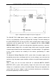
Instruction manual for SINLINE PRO 10000 series power supply units Figure 1: Simplified block diagram of the power supply unit The SINLINE PRO 10000 power supply unit is a modern electronic device that serves as an autonomous source of sinusoidal 230 V voltage. The device belongs to the LINE–INTERACTIVE (VI) class of UPSs, which includes power supply units that synchronize with the power grid.
Instruction manual for SINLINE PRO 10000 series power supply units The dedicated DPC system controls the operation of the power supply unit, and has an extremely precise and rapidly acting system for detecting overloads and output short-circuits during battery operation. In mains operation mode, short-circuit protection is provided by fuses, with overloads being brought to the user's attention both audibly and optically.
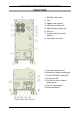
Instruction manual for SINLINE PRO 10000 series power supply units STRUCTURE 1) BYPASS switch cover 2) Fans 3) Adapter card slot plug 4) USB communication link 5) RS232 communication link 6) EPO link 7) Fusible cut-out for internal batteries 8) Connection links cover 9) AC input automatic fuses 10) Mechanical cable mounting grip 11) Service BYPASS switch/UPS 12) Connection link 13) Fusible cut-out for external battery packs 14) Device earthing point 15) Mounting holders Figure 2: Views of the rear panel
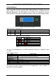
Instruction manual for SINLINE PRO 10000 series power supply units USER INTERFACE The user interface consists of a four-button keypad located on the upper cover of the power supply unit, an LCD, and three LEDs. They allow the user to monitor the unit's operating parameters, and also modify some of them. The method of using the interface and the meanings of individual parameters have been described hereunder.
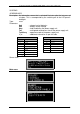
Figure 1: Organisation of screens Instruction manual for SINLINE PRO 10000 series power supply units 2010/08/24 www.ever.
Instruction manual for SINLINE PRO 10000 series power supply units SCREENS SCREENSAVER Description: An information screen that is activated 5 minutes after the last press of a button. This is accompanied by the switching off of the LCD panel's backlight.
Instruction manual for SINLINE PRO 10000 series power supply units The main menu comprises tree screens. Switching between screens is effected by means of the ▼▲ keys. A selection is confirmed by pressing the key, whereafter a submenu may be selected in the chosen menu also by means of the ▼▲ keys. The arrow on the left of the submenu name indicates the current position. Selections are confirmed by the key. To proceed to a higher level, press the ESC key.
Instruction manual for SINLINE PRO 10000 series power supply units Screen view: BATTERY 3/4 Description: Battery-related parameters Type: read Parameters U – battery section voltage I – absolute battery current value Q – charge level of batteries (calculated for the current load) Tau – anticipated autonomous time StanAku.
Instruction manual for SINLINE PRO 10000 series power supply units CONTROL submenu The CONTROL submenu is divided into three groups. The menu can be navigated in the same way as described above. The user may alter the configuration of the power supply unit only if individual items can be changed under specific conditions. Cf. table hereunder. BACKUP X Buzzer X Czas.Wyl.
Instruction manual for SINLINE PRO 10000 series power supply units CONTROL 1/3 Description: Settings of power supply unit control flags. Type: read/save Parameters AwaryjneWylaczenie – forced passage of the power supply unit to the EPO mode from the user interface level UPS – switching the power supply unit on/off Buzzer – switching on/off of battery charge status signalling for the BACKUP mode Screen view: CONTROL 2/4 Description: Settings of power supply unit control flags.
Instruction manual for SINLINE PRO 10000 series power supply units CONFIGURATION submenu The CONFIGURATION submenu is divided into four groups. The menu can be navigated in the same way as described above. The user may change the power supply unit parameter values if the keypad is not locked. Screens are selected using the ▲▼ keys, and confirmation given by pressing . As in the case of parameters, selections are made using the ▲▼ keys and confirmation given by pressing the key.
Instruction manual for SINLINE PRO 10000 series power supply units CONFIGURATION 3/4 Description: Power supply unit parameters Type: read/save Parameters Poj. z STB. – minimal charge level that the batteries must attain in order for the power supply unit to start up following a discharge ProgKas.Prz. – load level at which the power supply unit ceases to signal an overload Screen view: CONFIGURATION 4/4 Description: Power supply unit parameters Type: read/save Parameters Poj.Aku.
Instruction manual for SINLINE PRO 10000 series power supply units ALARMS submenu The ALARMS submenu comprises two screens. The menu can be navigated in the same way as described above. Screens are selected using the ▲▼ keys, and confirmation given by pressing . Alarm screens inform about the type of alarm which caused the power supply unit to switch to EMERGENCY mode. ALARMS 1/2 Description: Power supply unit alarms.
Instruction manual for SINLINE PRO 10000 series power supply units STATISTICS submenu The STATISTICS submenu comprises four screens. The menu can be navigated in the same way as described above. Screens are selected using the ▲▼ keys, and confirmation given by pressing . The screens display information concerning the operational history of the power supply unit. STATISTICS 1/4 Description: Statistical data.
Instruction manual for SINLINE PRO 10000 series power supply units STATISTICS 3/4 Description: Statistical data. Type: read Parameters Rozładowan – the number of total discharges of the power supply unit's batteries AVR Podw. – the number of activations of the AVR system resulting in an increase in voltage value – the number of activations of the AVR system AVR ObniŜ. resulting in a decrease in voltage value Screen view: STATISTICS 4/4 Description: Statistical data.
Instruction manual for SINLINE PRO 10000 series power supply units PANEL SETTINGS submenu The PANEL SETTINGS submenu contains a single screen. The menu can be navigated in the same way as described above. The user can change the values of power supply unit parameters. Confirm a screen by pressing , select a parameter by means of the ▲▼ keys and confirm by pressing the key. The PANEL SETTINGS menu contains numerical parameters.
Instruction manual for SINLINE PRO 10000 series power supply units INDUSTRIAL WORK SAFETY INSTRUCTIONS TRANSPORT • exercise particular care when transporting; • because of its weight, the device has been fitted with rubber wheels; • the appliance should be operated and stored in conditions concordant with those set forward in the specification; ELECTRICAL SAFETY • it is forbidden to work on one's own under conditions constituting a threat to life and/or health; • during a momentary short-circuit,
Instruction manual for SINLINE PRO 10000 series power supply units INSTALLATION NOTE! Before installing the appliance, you must acquaint yourself with the principles of industrial work safety set forward in the previous chapter. UNPACKING Carry out a visual inspection of the power supply unit immediately upon delivery. Although the product is packaged, the appliance could have undergone damage due to inappropriate transport conditions. If any damage is determined, inform the carrier or seller.
Instruction manual for SINLINE PRO 10000 series power supply units INSTALLATION OF THE POWER SUPPLY UNIT The weight of the device should be considered when selecting the point of installation. The unit should be used only in rooms where the levels of dustiness, temperature and humidity are concordant with the device specifications. Appropriate cooling conditions must be ensured for the unit to work correctly.
Instruction manual for SINLINE PRO 10000 series power supply units Figure 3: Connecting battery modules Connecting modules Note! When the safeguards are active, the voltage on the connection terminals is dangerous to health and/or life. All safeguards must be switched off before carrying out any installation work! 1. Switch off the power supply unit by means of the user interface (CONTROL 1/3; UPS). 2. Set fuses F3 and F4 to OFF. 3.
Instruction manual for SINLINE PRO 10000 series power supply units 10. 11. 12. 13. 14. 15. 16. Replace the fuse-elements in their respective mounts. Close the fusible cut-out mounts of all connected battery modules in turn. Close the F1 mount in the power supply unit. Wait at least 10 sec. Close the F2 mount in the power supply unit – the batteries are connected. Switch fuses F3 and F4 ON. Set the appropriate battery-related parameters of the power supply unit (CONFIGURATION 4/4). 17.
Instruction manual for SINLINE PRO 10000 series power supply units CONNECTING THE POWER SUPPLY UNIT Connecting elements Figure 4: Connecting elements with safeguards F3 F4 – safeguard of the service BYPASS line – primary line protection WEJ AC LB L N – input terminals – service BYPASS phase line – primary phase line – primary neutral line WYJ AC L N – output terminals – output phase line – output neutral line WEJ DC + - – input terminals of the external battery module – positive pole – negative po
Instruction manual for SINLINE PRO 10000 series power supply units The system must be structured in such a way as to make possible the disconnection of the power supply unit from the mains, e.g. by the switching of integrated overcurrent cut-outs. NOTE! The UPS should be connected by qualified and authorised personnel only. NOTE! The UPS is completely disconnected from the power network only when the power supply cord is disconnected.
Instruction manual for SINLINE PRO 10000 series power supply units Once it has been correctly connected, start up the power supply unit by performing the following activities in the order mentioned: 1) 2) 3) 4) Check whether fuses F3 and F4 are OFF; if not, set them OFF. Open the mounts of fusible cut-outs F1 and F2. Insert an appropriate fuse-element in mount F1 (do not close the mount). Insert an appropriate fuse-element in mount F5, and then close it in order to close the circuit.
Instruction manual for SINLINE PRO 10000 series power supply units OPERATING MODES OF THE POWER SUPPLY UNIT Figure 5: Graph presenting the operation modes of the power supply unit UNKNOWN mode An intermediate state that occurs when the power supply unit is started up following energisation. INIT (INITIALISATION) mode An intermediate state that occurs following initiation of the hardware platform by means of start-up values or during a return from EMERGENCY mode.
Instruction manual for SINLINE PRO 10000 series power supply units BACKUP mode (BATTERY OPERATION) If the primary power line does not satisfy the mains correctness criteria, the power supply unit switches to the BACKUP mode (battery operation mode). In BACKUP mode, the inverter supplies power to the battery outputs. STOP mode The power supply unit is logically switched off (from the user interface), and no voltage satisfying the correctness criteria is present on the primary line.
Instruction manual for SINLINE PRO 10000 series power supply units mode) only when the overload falls below the set level (CONFIGURATION 3/4;ProgKas.Prz.). If in NORMAL operation mode the overload rises to 105%, the unit will start signalling this development by a continuous sound and the appropriate message on the display. As in the case of BACKUP mode, this state will last until the overload falls below the set level (CONFIGURATION 3/4;ProgKas.Prz.).
Instruction manual for SINLINE PRO 10000 series power supply units Figure 7: Internal battery protection It is necessary to observe the instruction written in the frame below the fuses, namely that the fuses must be activated in the appropriate order. F1 should be activated first, and F2 10 sec. later. Failure to follow this instruction may damage the power supply unit. Fusible cut-out F5 protects the terminal of the external battery module and is located to the right of the terminals.
Instruction manual for SINLINE PRO 10000 series power supply units AVR The power supply unit is equipped with an AVR (Automatic Voltage Regulation) system that immediately corrects small drops (AVR - increasing) and rises in mains voltage, so as to ensure that receivers enjoy the proper supply conditions without using up the power gathered in batteries. EPO The EPO (Emergency Power Off) is a mechanism that cuts off the energy supply to receivers at the unit's output in extreme situations (e.g. a fire).
Instruction manual for SINLINE PRO 10000 series power supply units Switch in the UPS position – normal operation of the power supply unit. Switch in the BYPASS position – the BYPASS line is switched to the input terminals. Switching may be performed at any time. COOPERATION OF THE POWER SUPPLY UNIT WITH A PC RS232 AND USB COMMUNICATION The user can modify the parameters of the power supply unit not only from the user interface (panel), but also by means of the dedicated PowerSoft software.
Instruction manual for SINLINE PRO 10000 series power supply units Installing a management card 1) 2) 3) 4) 5) 6) 7) 8) 9) 10) 11) 12) 13) 14) Switch on the power supply unit by means of the user interface (CONTROL 1/3; UPS). Set safeguards F3 and F4 OFF. Switch off safeguards F1, F2 and F5 by opening the fusible cut-out mounts. The safeguards do not have to be switched off in any special order. Wait for approx. 30 sec. in order to discharge the internal capacities of the unit.
Instruction manual for SINLINE PRO 10000 series power supply units INSTALLING AND CONFIGURING POWERSOFT PERSONAL Installing on a Windows system Before installing the PowerSoft software, you should: • • uninstall your current version of PowerSoft and other monitoring software (if the user is replacing an emergency power supply unit that protects his PC), if you are installing a power supply unit that communicates with the PC by means of a USB connection, the USB cable should be disconnected from the PC.
Instruction manual for SINLINE PRO 10000 series power supply units rpm –ivh powersoftpersonal-x.x.x.i386.rpm Users working with the software must possess system administrator privileges (root) in order to install and subsequently use the programme. Following installation, the package is located in the catalogue /usr/local/powersoft. In order to uninstall the application, write the following command in the command line: rpm –ev powersoftpersonal-x.x.
Instruction manual for SINLINE PRO 10000 series power supply units Linux/Unix systems PowerSoft software for systems from the Linux/Unix family may be updated using a new version of the package, downloaded from www.ever.eu. In the case of CentOS, RedHat, Suse Linux and Fedora Core systems, updates may be performed by means of the following command: rpm –Uv powersoftlite-x.x.x For Debian and FreeBSD systems, we recommend uninstalling the old version of the software and then installing the new version.
Instruction manual for SINLINE PRO 10000 series power supply units COOPERATION OF THE POWER SUPPLY UNIT WITH ELECTRICITY GENERATORS SINLINE PRO 10000 series UPS units are class LINE-INTERACTIVE devices, which synchronise with the voltage of the power grid. By definition, the unit tolerates mains voltage fluctuations and frequency changes within a certain range with reference to a model frequency of 50 Hz (cf. table of technical parameters).
Instruction manual for SINLINE PRO 10000 series power supply units TECHNICAL PARAMETERS INSTALLATION GUIDELINES PARAMETER \ POWER SUPPLY UNIT Apparent/active power POWER SUPPLY PARAMETERS Power supply system topology Rated voltage Rated current Rated frequency input Minimum cable diameter Primary and BYPASS line safeguards 10 kVA 8 kW 1P3W 230 V 46 A 50 Hz 10 mm2 Switch fuse 80 A gG Switch fuse 80 A gG OUTPUT PARAMETERS Output system topology Nominal input voltage Rated current Minimum cable diameter
Instruction manual for SINLINE PRO 10000 series power supply units TECHNICAL DATA PARAMETERS SINLINE PRO 10000 10 kVA 8 kW Output power 1) GENERAL DATA Topology Total efficiency for Pmax AC/AC Cooling Protection level Working environment Working temperature 2) Storage temperature Relative humidity during operation Relative humidity during storage Height above sea level 3) NETWORK POWER MODE Input voltage Input voltage frequency Output voltage range Switching thresholds: mains-ups Output voltage shape Mai
Instruction manual for SINLINE PRO 10000 series power supply units INFORMATION CONCERNING LEGAL PROVISIONS AND THE GUARANTEE DECLARATION OF CONFORMITY The power supply unit has been manufactured in Poland and its construction is concordant with the provisions of the pertinent standards. GUARANTEE The guarantee for the appliance constitutes a separate document, which is attached to the product. This document must meet all formal requirements (e.g.. date of sale, stamp of the seller).