SINLINE XL series UPS – Instruction Manual TABLE OF CONTENTS INTRODUCTION .................................................................................................................................................. 3 GENERAL INFORMATION ................................................................................................................................. 3 PURPOSE OF THE POWER SUPPLY.............................................................................................................
SINLINE XL series UPS – Instruction Manual INTRODUCTION Thank you for purchasing the EVER SINLINE XL UPS (UPS). It belongs to the latest series of state-of-the-art power supply devices designed to work with servers, small computer networks, as well as workstations.
SINLINE XL series UPS – Instruction Manual GENERAL FEATURES OF THE UPS • Output true sine wave, also generated in battery operating mode; • DPC – digital control of operating parameters of the back-up, such as: • shape of the output voltage, frequency of the output voltage, charge level of batteries; voltage and current of batteries; measurement of battery set capacity (displayed on the front panel); battery life; temperature of essential parts of the UPS; Digital monitorin
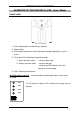
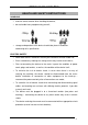
SINLINE XL series UPS – Instruction Manual ELEMENTS OF THE SINLINE XL UPS - Tower Model FRONT PANEL Fig. 1: Front panel 1) LEDs indicating the available battery capacity. 2) Power switch 3) LED indicating whether the AVR (Automatic Voltage Regulation) system is active 4) Two-colour LED indicating the operating mode: a. Mains operation mode – constant green light b.
SINLINE XL series UPS – Instruction Manual >85% >60% >30% >5% The right column of green LEDs indicates the percentage load level of the UPS in both the mains and battery operation mode. If the top LED is lit in red and the UPS is emitting a continous sound signal, this indicates that the UPS has overloaded. However, if the red LED is blinking and the UPS is emitting a quick intermittent signal, this indicates a shorting at the back-up's output.If the UPS malfunctions, it switches off automatically.
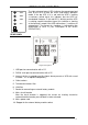
SINLINE XL series UPS – Instruction Manual ELEMENTS OF THE SINLINE XL UPS – Rack Model FRONT PANEL Fig. 3: Front panel 1) Circuit breaker After the circuit breaker is triggered, the reason for shorting should be removed and the breaker pressed back in to be activated. 2) Power switch 3) Two-colour LED indicating the operating mode: a. Mains operation mode – constant green light b.
SINLINE XL series UPS – Instruction Manual LED is lit in red and the UPS is emitting a continous sound signal, this indicates that the UPS has overloaded. However, if the red LED is blinking and the UPS is emitting a quick intermittent signal, this indicates a shorting at the back-up's output. If the UPS malfunctions, it switches off automatically. The reason for shutdown is indicated by the combination of LEDs lit (see "Description of the UPS’S OPERATION"). REAR PANEL Fig.
SINLINE XL series UPS – Instruction Manual HEALTH AND SAFETY INSTRUCTIONS HANDLING • exercise utmost caution when handling the device; • do not handle heavy equipment by yourself; • storage and operation of the device should take place in conditions conforming to its specification.
SINLINE XL series UPS – Instruction Manual • A device powered via a cord with a plug has an earthing lead that carries away the leakage current from the receivers (e.g. computer equipment) – the total leakage current must not exceed 3.5mA. Users are forbidden to carry out any maintenance activities, as they may lead to injury or death. Any repairs and replacement of batteries should be conducted only by a qualified representative of the technical support.
SINLINE XL series UPS – Instruction Manual Check the contents of the packaging. The packaging should contain: • the UPS. • a CD-ROM with the PowerSoft software and complete instruction manual, • quick reference guide, • 1 communication cable to connect the back-up to a computer via RS232, • 1 communication cable to connect the back-up to a computer via USB, • 2 outlet power cords, • warranty card, • 2 moving handles for cabinet installation (Rack Model only).
SINLINE XL series UPS – Instruction Manual 1. Install the moving handles in the back section of the cabinet. 2. Supporting the back-up's base with hand, slide UPS onto the previouslyinstalled handles. 3. Screw the front (fixed) handles of the UPS to the rack's frame. Fig. 5: SINLINE RACK 19" – Top Wiew WARNING!! The device must not be installed in the proxmity of flammable materials! THE BATTERY MODULE SINLINE XL UPSs have the option of connecting an additional battery module.
SINLINE XL series UPS – Instruction Manual Connecting the module 1. Turn the UPS off with the power switch located on the front panel and disconnect it from the mains by removing the power cord plug from the mains socket. 2. Remove the stopper covering the connector (rear panel). 3. Connect the battery module to the UPS. 4. Connect the UPS to the mains and then turn it on with the power switch on the front panel. 5.
SINLINE XL series UPS – Instruction Manual EVER MANAGEMENT CARD The Ever management card is an optional component that may be installed by the user. Installing the card renders the communication via RS232 and USB impossible. Installing themanagement card – Tower and Rack Models 1. Turn the UPS off with the power switch on the front panel and disconnect it from the mains by removing the power cord plug from the mains socket. 2. Remove the screws holding the cover of the card slot and remove the cover (Fig.
SINLINE XL series UPS – Instruction Manual Installing themanagement card 1. Turn the UPS off with the power switch on the front panel and disconnect it from the mains by removing the power cord plug from the mains socket. 2. Remove the screws holding the cover of the card slot and remove the cover (Fig. 7a). 3. Connect the cable located in the opening to the card (Fig. 7b). 4. Slide the card into the slot (Fig. 7c). 5. Replace the screws, fixing the card to the rear panel (Fig. 7d). a. b. c. d. Fig.
SINLINE XL series UPS – Instruction Manual Due to the type and placement of cut-outs present in the UPS the safety circuits of the building function as one of the protection measures. This is essential to provide the UPS with shorting protection. Protection parameters of the buildings' installations should be adjusted according to the type and size of load connected to the installation.
SINLINE XL series UPS – Instruction Manual WARNING! The output side of the back-up only allows the TN-S mains configuration. Output installation Even though the input side allows both types of terminals, the output installation arranged inconsistently with this instruction may damage the UPS. The scheme of correctly arranged output connections is presented in Fig. 10. Fig. 10: Output installation of the UPS The arrangement of terminals of output sockets of the UPS is presented on Fig. 11. Fig.
SINLINE XL series UPS – Instruction Manual FIRST START WARNING! The UPS may only be connected to a ~230V mains socket equipped with a grounding bolt. Electric installation of the building to which the back-up is connected must be protected against overloads and shorting. After unpacking, place the device in the chosen location and connect it to the mains in order to charge the internal batteries. Charging time of batteries can be found in the technical parameters table.
SINLINE XL series UPS – Instruction Manual DESCRIPTION OF THE BACK-UP’S OPERATION GENERAL INFORMATION The SINLINE XL UPS is a state-of-the-art electronic device constituting an autonomous source of true sine wave voltage of ~230V. This device belongs to the group of LINE-INTERACTIVE (VI)-class UPSs, which includes UPSs that synchronise with the mains.
SINLINE XL series UPS – Instruction Manual This UPS utilises an innovative charging method reserved only for the most advanced UPSs (CBC - COOL BATTERY CHARGING) which utilises the elements of an internal inverter. During the mains operation mode it charges the batteries and in the back-up operation mode it converts the internal energy of the battery into the alternating current to power the protected devices.
SINLINE XL series UPS – Instruction Manual STAND-BY MODE The UPS switches to STAND-BY mode when the batteries are completely discharged or when it receives an appopriate command from the control software. The UPS will wait for the mains voltage of correct parameters to come back in order to return to the mains operation mode. EMERGENCY MODE In this mode the UPS cuts the power from its outlets and signals all malfunctions and their origins.
SINLINE XL series UPS – Instruction Manual SAFEGUARDS Against overloads An overload is signalled by constant shining of the top LED (red) in the load indication column and a continuous sound signal. If the UPS is operating in back-up mode and the overload lasts longer than 10 seconds, the UPS will switch to emergency operation mode. Outlet sockets are disconnected from the power supply.
SINLINE XL series UPS – Instruction Manual COMMUNICATION BETWEEN THE UPS AND THE COMPUTER COMMUNICATION VIA RS232 OR USB SINLINE XL series UPSs come with enhanced control features. The UPS is delivered with a built-in RS232 and USB communication port, and the PowerSoft software package. To ensure correct cooperation, the UPS must be connected to the computer with the provided cable.
SINLINE XL series UPS – Instruction Manual In the case of a UPS connected to the computer via a USB cable, when the software installation is complete, the PowerSoft Personal installer will ask the user to connect the USB cable to the computer. The system will announce that a new device has been found and will propose to install the drivers.
SINLINE XL series UPS – Instruction Manual Debian For Debian systems the software is provided in the form of a DEB package. The software is installed via the following command: dpkg –-install PowerSoftpersonal-x.x.x.deb To uninstall the application enter the following command: dpkg –-remove PowerSoft FreeBSD For FreeBSD systems the software is provided in the form of the default package format designed for FreeBSD systems. The software is installed via the following command: pkg_add PowerSoftpersonal-x.x.
SINLINE XL series UPS – Instruction Manual Linux/Unix systems In the case of Linux/Unix systems PowerSoft can be updated by downloading the new package from www.ever.eu. In the case of CentOS, RedHat, Suse Linux, and Fedora Core PowerSoft can be updated by entering the following command: rpm –Uv PowerSoftlite-x.x.x In the case of Debian and FreeBSD systems we recommend uninstalling the old version and then installing the new version of the software.
SINLINE XL series UPS – Instruction Manual CONFIGURING THE UPS'S PARAMETERS PowerSoft Plus allows the user to change certain parameters of the UPS. To enable this, the UPS must be connected to the computer with the cable provided by the manufacturer. A list of these parameters together with available settings is presented in the tables below. Table 2 PARAMETER/FUNCTION Acoustic signalling Delay before standby mode FACTORY SETTING On 90 sec. CUSTOM SETTINGS On/off 0 – 1000 sec.
SINLINE XL series UPS – Instruction Manual of the UPS, which causes an overload detection and consequently a shutdown. This situation may occur in the case of: Television sets and monitors (as they are switched on the picture tube is degaussed which temporarily requires a lot of power), Laser printers (drum warming cycle), Other products with similar operating features. Therefore, if a UPS is to be used with equipment other than computers, its compatibility with equipment used must be verified.
SINLINE XL series UPS – Instruction Manual must be connected with a cable with RJ45 terminators. The existing ETHERNET UTP line should be connected to the other outlet socket of the filter. The filter is symmetrical, so it does not matter to which of the two sockets the ETHERNET UTP line is connected.
SINLINE XL series UPS – Instruction Manual TECHNICAL PARAMETERS – Tower Model PARAMETERS UPS TYPE Output power 1) SINLINE XL 1800 SINLINE XL 2200 2200VA/ 1540W SINLINE XL 3000 3000VA/ 2100W 1800VA/ 1260W Office or industrial rooms with low level of pollution +10 ÷ +35 °C 0 ÷ +45 °C 20 ÷ 80 % (without condensation) 20 ÷ 95 % (without condensation) up to 1000 m < 10 m Working environment Operating temperature 2) Storage temperature Relative humidity for operation Relative humidity for storage Altitude (
SINLINE XL series UPS – Instruction Manual TECHNICAL PARAMETERS – Rack Model PARAMETERS UPS TYPE Output power 1) Working environment Operating temperature 2) Storage temperature Relative humidity for operation Relative humidity for storage Altitude (above sea level) 3) Maximum length of outgoing cables MAINS OPERATION MODE Input voltage 4), 5) Frequency of input voltage Range of output voltage 5) Switching thresholds: Mains – UPS 4), 5) Shape of output voltage Filtering of output voltage Time to switch to
SINLINE XL series UPS – Instruction Manual INFORMATION REGARDING REGULATIONS AND WARRANTY DECLARATION OF CONFORMITY The UPS was manufactured in Poland and its structure conforms to appropriate subject matter standards. WARRANTY A separate document attached to the product constitutes the warranty. The document must meet all formal requirements (e.g. the following fields must be populated: serial number, model/type, date of sale, and dealer stamp).