CATALOG C-CF-0 4 1 7 AHEAD OF THE FLOW ® Copper Fittings
Business-to-Business Solutions Look to NIBCO for technology leadership. The velocity with which e-business evolves demands that new products and services be continuously developed and introduced to keep our customers at the center of our business efforts. NIBCO provides an entire suite of business-to-business solutions that is changing the way we interact with customers. NIBCOpartner.
www.nibco.com AHEAD OF THE FLOW ® Visit our website for the most current information. Table of Contents Specifications . . . . . . . . . . . . . . . . . . . . . . . . . . . . . . . . . . . . . . . . . . . . . 4 Wrot & Cast Pressure Fittings . . . . . . . . . . . . . . . . . . . . . . . . . . . . . 5-21 Cast Copper Alloy Flared Fittings . . . . . . . . . . . . . . . . . . . . . . . . . .
www.nibco.com Revision 6/1/2015 Specifications All of the advantages found in copper as a metal have been capitalized to the utmost in the manufacture of NIBCO® Fittings. Because of the accuracy of construction and design, copper plumbing is more efficient and less expensive. NIBCO manufactures nine general types of fittings: Wrot Pressure; Cast Pressure; Wrot Drainage; Cast Drainage; Flanges; Flared Tube; Threaded Bronze; Insert Fittings for PEX; Barbed Insert Fittings for Polybutylene.
www.nibco.com AHEAD OF THE FLOW ® Wrot and Cast Pressure Fittings 600 Series – Wrot 700 Series – Cast Adapters . . . . . . . . . . . . . . . . . . . . . . . . . . . . . . . . . . . . . . . . . . . . . . . 6-8 Air Chambers . . . . . . . . . . . . . . . . . . . . . . . . . . . . . . . . . . . . . . . . . . . . . 8 Bulkhead Fittings . . . . . . . . . . . . . . . . . . . . . . . . . . . .
www.nibco.com Revision 6/17/2020 ADAPTERS 603 Adapter C x F – Wrot NOM. SIZE 1/8 1/8 x 1/4 1/4 1/4 x 3/8 3/8 3/8 x 1/4 3/8 x 1/2 3/8 x 3/4 1/2 1/2 x 1/4 1/2 x 3/8 1/2 x 3/4 5/8 x 1/2 5/8 x 3/4 3/4 3/4 x 1/2 3/4 x 1 1 1 x 1/2 1 x 3/4 1 x 1 1/4 1 1/4 1 1/4 x 1 1 1/4 x 1 1/2 1 1/2 1 1/2 x 1 1 1/2 x 1 1/4 1 1/2 x 2 2 2 x 1 1/2 2 1/2 3 4 703-2 703 Adapter C x F – Cast APPROX. NET WT./LBS. DIM. A INCHES 0.03 0.03 0.03 0.04 0.04 0.03 0.09 0.10 0.08 0.06 0.04 0.14 0.11 0.13 0.15 0.10 0.21 0.24 0.14 0.
www.nibco.com AHEAD OF THE FLOW ® Revision 3/12/2020 ADAPTERS continued 604 Adapter C x M – Wrot NOM. SIZE 1/8 x 1/4 1/4 1/4 x 1/2 3/8 3/8 x 1/4 3/8 x 1/2 3/8 x 3/4 1/2 1/2 x 1/4 1/2 x 3/8 1/2 x 3/4 1/2 x 1 5/8 x 1/2 5/8 x 3/4 3/4 3/4 x 1/2 3/4 x 1 1 1 x 1/2 1 x 3/4 1 x 1 1/4 1 x 1 1/2 1 1/4 1 1/4 x 3/4 1 1/4 x 1 1 1/4 x 1 1/2 1 1/2 1 1/2 x 1 1 1/2 x 1 1/4 1 1/2 x 2 2 2 x 1 1/2 2 1/2 3 4 704 Adapter C x M – Cast APPROX. NET WT./LBS. DIM. B INCHES 0.03 0.03 0.07 0.04 0.06 0.09 0.15 0.07 0.
www.nibco.com Revision 7/23/2018 ADAPTERS continued 704-2-H Hose Adapter Ftg x Hose – Cast NOM. SIZE APPROX. NET WT./LBS. DIM. B INCHES 0.16 15/8 3/4 F x 3/4 H NOTE: Fits /2," /8" and /4" Garden Hose. 1 5 3 AIR CHAMBERS B USHINGS ULKHEAD B FITTINGS 618 Flush Bushing Ftg x C – Wrot 750 Bulkhead Fitting C x C – Cast NOM. SIZE 1/2 3/4 1 1 1/2 2 APPROX. NET WT./LBS. DIM. A INCHES DIM. B INCHES 0.48 0.77 1.30 2.87 3.
www.nibco.com AHEAD OF THE FLOW ® CAPS C OUPLINGS 600 Reducing Coupling C x C – Wrot 617 Tube Cap C – Wrot NOM. SIZE APPROX. NET WT./LBS. DIM. N INCHES 0.00 0.01 0.01 0.02 0.03 0.05 0.07 0.10 0.16 0.27 0.47 0.78 1.66 1/32 1/8 1/4 3/8 1/2 5/8 3/4 1 1 1/4 1 1/2 2 2 1/2 3 4 1/16 3/32 1/8 1/8 3/16 5/32 3/32 1/8 5/32 7/32 7/32 1/4 717 Tube Cap C – Cast NOM. SIZE APPROX. NET WT./LBS. DIM. N INCHES 5.48 9.07 7/16 5 6 17/32 717-D Drain Cap – Cast NOM.
www.nibco.com Revised 7/23/2018 COUPLINGS continued 600-DS Coupling with Dimpled Tube Stop C x C – Wrot 601 Coupling without Stop C x C – Wrot NOM. SIZE NOM. SIZE 3/16 O.D. 1/8 5/16 O.D. 1/4 3/8 1/2 5/8 3/4 7/8 1 1 1/4 1 1/2 2 2 1/2 3 3 1/2 4 5 6 8 APPROX. NET WT./LBS. DIM. A INCHES 0.00 0.01 0.01 0.01 0.01 0.03 0.04 0.06 0.09 0.11 0.15 0.22 0.40 0.66 1.00 1.45 1.93 3.53 5.63 14.
www.nibco.com AHEAD OF THE FLOW ® C ROSSES Revision 12/6/2019 ELBOWS 706-2 45° Fitting Elbow Ftg x C – Cast 606 45° Elbow C x C – Wrot 735 Cross C x C x C x C – Cast NOM. SIZE 3/8 ▲ 1/2 ▲ 3/4 ▲1 1 1/4 1 1/2 2 2 1/2 APPROX. NET WT./LBS. DIM. A INCHES 0.08 0.14 0.28 0.54 0.78 1.05 2.00 2.
www.nibco.com Revised 7/23/2018 ELBOWS continued 707 90° Elbow – Close Rough C x C – Cast NOM. SIZE 1 1/4 x 1/2 ▲ 1 1/4 x 3/4 1 1/4 x 1 ▲ 1 1/2 x 1 1 1/2 x 3/4 1 1/2 x 1/2 2 x 1 1/4 2x1 2 x 3/4 2 1/2 x 2 3 x 2 1/2 3x2 4x3 APPROX. NET WT./LBS. DIM. C INCHES DIM. D INCHES 0.28 0.34 0.42 0.46 0.45 0.40 0.86 0.78 0.69 2.16 2.26 2.68 5.
www.nibco.com AHEAD OF THE FLOW ® Revised 3/12/2020 E LBOWS continued 607-2-LT 90° Fitting Elbow – Long Radius Ftg x C – Wrot NOM. SIZE 1/8 1/4 3/8 1/2 1/2 x 3/8 5/8 3/4 1 1 1/4 1 1/2 2 2 1/2 3 4 APPROX. NET WT./LBS. DIM. B INCHES DIM. C INCHES 0.01 0.02 0.05 0.08 0.06 0.11 0.16 0.32 0.47 0.66 1.27 2.16 3.10 7.
www.nibco.com Revised 7/23/2018 E LBOWS continued 707-3-5-A 90° Hy-Set Elbow C x F – Cast NOM. SIZE ▲ 1/2 APPROX. NET WT./LBS. DIM. C INCHES DIM. E INCHES 0.20 9/16 27/32 707-3-6 90° Union Elbow C x F – Cast NOM. SIZE ▲ 1/2 ▲ 3/4 1 APPROX. NET WT./LBS. DIM. A INCHES 0.31 0.48 0.77 11/16 111/32 11/2 DIM. E INCHES 7 /8 1 11/4 707-4-6 90° Union Elbow C x M – Cast NOM. SIZE 707-6 90° Union Elbow C x C – Cast APPROX. NET WT./LBS. DIM. A INCHES DIM. E INCHES NOM. SIZE 0.20 0.
www.nibco.com AHEAD OF THE FLOW ® Revision 7/23/2018 F ITTING REDUCERS 600-2 Fitting Reducer Ftg x C – Wrot NOM. SIZE 1/4 x 1/8 3/8 x 1/8 3/8 x 1/4 1/2 x 1/4 1/2 x 3/8 5/8 x 1/4 5/8 x 3/8 5/8 x 1/2 3/4 x 1/4 3/4 x 3/8 3/4 x 1/2 3/4 x 5/8 1 x 3/8 1 x 1/2 1 x 5/8 1 x 3/4 1 1/4 x 1/2 1 1/4 x 3/4 1 1/4 x 1 1 1/2 x 1/2 1 1/2 x 3/4 1 1/2 x 1 1 1/2 x 1 1/4 2 x 1/2 2 x 3/4 2x1 2 x 1 1/4 2 x 1 1/2 2 1/2 x 1 2 1/2 x 1 1/4 2 1/2 x 1 1/2 2 1/2 x 2 3 x 1 1/4 3 x 1 1/2 3x2 3 x 2 1/2 3 1/2 x 3 APPROX.
www.nibco.com Revised 7/23/2018 P LUGS TRAPS & S HANGERS TEES 616 Fitted Plug Ftg - Wrot 623 Copper Hanger Strap 705 Baseboard Tee C x F x C – Cast NOM. SIZE APPROX. NET WT./LBS. 3/8 1/2 3/4 DIM. A INCHES / / 5/ 32 1 16 3 32 0.012 0.02 0.05 SIZE APPROX. NET WT./LBS. 3/4" Wide x 25 Ft. Roll 1.93 R ETURN BENDS NOM. SIZE 1/2 x 1/8 x 3/4 ▲ 1/2 x 1/8 x 1/2 3/4 x 1/8 x 1 ▲ 3/4 x 1/8 x 3/4 ▲ 1 x 1/8 x 1 ▲ 1 1/4 x 1/8 x 1 1/4 APPROX. DIMENSIONS NET WT. INCHES LBS.
www.nibco.com AHEAD OF THE FLOW ® Revised 2/28/2020 TEES continued 710-3 Tee F x F x C – Cast NOM. SIZE ▲ ▲ ▲ ▲ 1/2 3/4 3/4 x 1/2 x 1/2 3/4 x 1/2 x 3/4 3/4 x 3/4 x 1/2 APPROX. DIMENSIONS NET WT. INCHES LBS. C E S 0.20 0.37 0.20 0.21 0.31 9/16 7/8 7/8 11/16 1 1 9/16 7/8 31/32 9/16 15/16 11/16 31/32 1 31/32 710-3-4 Tee M x F x C – Cast NOM. SIZE ▲ 3/4 3/4 x 3/4 x 1/2 APPROX. DIMENSIONS NET WT. INCHES LBS. C E S 0.32 0.
www.nibco.com Revision 9/6/2019 TEES continued 611 Tee C x C x C – Wrot continued NOM.
www.nibco.com AHEAD OF THE FLOW ® Revision 7/23/2018 TEES continued 611-HE Heat Exchanger Tee C x C x C – Wrot Tube slips entirely through fitting on small end of run. Sizes same as listed under 611 where tee has one or more reductions on one end of run. 611 Tee C x C x C – Wrot continued 611-2 Fitting Tee C x Ftg x C – Wrot NOM. SIZE NOM. SIZE APPROX. DIMENSIONS NET WT. INCHES LBS. C F G 5 8.29 227/32 227/32 313/32 5x2x5 9.47 227/32 529/32 313/32 5x4x4 8.
www.nibco.com Revised 7/23/2018 T RAPS TEES continued 712 Tee C x C x F – Cast NOM. SIZE 1/4 3/8 3/8 x 3/8 x 1/4 ▲ 1/2 ▲ 1/2 x 1/2 x 1/4 ▲ 1/2 x 1/2 x 3/8 ▲ 1/2 x 1/2 x 3/4 ▲ 3/4 3/4 x 1/2 x 3/4 ▲ 3/4 x 3/4 x 3/8 ▲ 3/4 x 3/4 x 1/2 3/4 x 3/4 x 1 ▲1 ▲ 1 x 1 x 1/2 ▲ 1 x 1 x 3/4 1 1/4 ▲ 1 1/4 x 1 1/4 x 1/2 ▲ 1 1/4 x 1 1/4 x 3/4 ▲ 1 1/4 x 1 1/4 x 1 1 1/2 ▲ 1 1/2 x 1 1/2 x 1/2 ▲ 1 1/2 x 1 1/2 x 3/4 ▲ 1 1/2 x 1 1/2 x 1 2 ▲ 2 x 2 x 1/2 ▲ 2 x 2 x 3/4 ▲2x2x1 713 Tee C x C x M – Cast APPROX.
www.nibco.com AHEAD OF THE FLOW ® Revision 7/23/2018 UNIONS V ENTURI 633-W Union C x C – Wrot NOM. SIZE 1/4 3/8 1/2 3/4 1 APPROX. NET WT./LBS. DIM. A INCHES 0.13 0.12 0.12 0.28 0.44 1/2 7/16 733-2 Fitting Union Ftg x C – Cast 621 Venturi Insert – Wrot NOM. SIZE Converts any tee into a special purpose venturi or scoop tee 1/2 3/4 1 APPROX. NET WT./LBS. DIM. B INCHES 0.23 0.36 0.50 19/32 15/8 127/32 7/16 7 /16 /2 1 NOM. SIZE APPROX. NET WT./LBS.
www.nibco.com Cast Copper Alloy Flared Fittings 100 Series – Heavy Flared 500 Series – Flared Adapters . . . . . . . . . . . . . . . . . . . . . . . . . . . . . . . . . . . . . . . . . . . . . . . . . . . . . . . Couplings . . . . . . . . . . . . . . . . . . . . . . . . . . . . . . . . . . . . . . . . . . . . . . . . . . . . . . Elbows . . . . . . . . . . . . . . . . . . . . . .
www.nibco.com AHEAD OF THE FLOW ® A DAPTERS Revision 7/23/2018 E LBOWS C OUPLINGS 104 Heavy Flared Adapter FL x M – Cast NOM. SIZE 3/4 1 APPROX. NET WT./LBS. 0.71 1.05 507 Flared 90° Elbow FL x FL – Cast DIM. L INCHES 1/2 2 31/4 NOM. SIZE 3/4 1 DIM. B INCHES 0.54 0.88 1.59 5.58 15/8 197/16 23/32 37/8 1/2 3/4 1 2 101 Heavy Flared Coupling FL x FL – Cast NOM. SIZE APPROX. NET WT./LBS. APPROX. NET WT./LBS. DIM. L INCHES 0.98 1.
www.nibco.com Revision 7/12/2019 NUTS 500 Tube Nut – Cast NOM. SIZE 3/4 1 APPROX. NET WT./LBS. DIM. B INCHES DIM. L INCHES 0.24 0.28 11/16 13/8 11/2 17/8 T EES 511 Flared Tee FL x FL x FL – Cast NOM. SIZE 1/2 APPROX. DIMENSIONS NET WT. INCHES LBS. B D K 0.66 15/8 15/8 15/8 WARNING: This product can expose you to c hemicals including lead, which is known to the State of California to cause cancer and birth defects or other reproductive harm. For more information go to www.
www.nibco.com AHEAD OF THE FLOW ® Wrot and Cast DWV Fittings Adapters . . . . . . . . . . . . . . . . . . . . . . . . . . . . . . . . . . . . . . . . . . . . . . . . . . . . 26-28 Bushings . . . . . . . . . . . . . . . . . . . . . . . . . . . . . . . . . . . . . . . . . . . . . . . . . . . . . . . 28 Cleanouts . . . . . . . . . . . . . . . . . . . . . . . . . . . . . .
www.nibco.com Revision 7/23/2018 ADAPTERS – SLIP JOINT ADAPTERS – SOIL PIPE 801-2-7 DWV Fitting Trap Adapter Ftg x SJ – Cast 805 DWV Soil Pipe Adapter C x Spigot – Cast NOM. SIZE 903-7 DWV Trap Adapter F x SJ – Wrot APPROX. NET WT./LBS. DIM. B INCHES 0.25 13/32 1 1/4 x 1 1/4 O.D. 901-2-7 DWV Fitting Trap Adapter Ftg x SJ – Wrot NOM. SIZE APPROX. NET WT./LBS. DIM. B INCHES 0.24 0.29 11/4 1 1/2 x 1 1/4 O.D. 1 1/2 x 1 1/2 O.D. 11/8 NOM. SIZE APPROX. NET WT./LBS. DIM.
www.nibco.com AHEAD OF THE FLOW ® Revision 7/23/2018 DAPTERS – A SPECIAL LEAD ADAPTERS – THREADED continued 801-T DWV Trap Adapter C x O.D. Tube – Cast 802-F DWV Threaded Piece C x M – Cast NOM. SIZE APPROX. NET WT./LBS. DIM. C INCHES 0.21 0.20 0.22 1/8 9/32 1 1/4 x 1 1/4 O.D. 1 1/2 x 1 1/4 O.D. 1 1/2 x 1 1/2 O.D. 7/32 ADAPTERS – THREADED 1 1/4 1 1/4 x 1 1/2 1 1/2 2 3 NOM. SIZE 1 1/4 1 1/2 2 APPROX. NET WT./LBS. DIM. B INCHES 0.05 0.06 0.05 3/8 3/8 APPROX. NET WT./LBS.
www.nibco.com Revision 7/23/2018 ADAPTERS – THREADED continued B USHINGS CLEANOUTS 904 DWV Adapter C x M – Wrot 801-2 DWV External Bushing Ftg x C – Cast 816 DWV Fitting Cleanout Ftg x Cleanout w/Plug – Cast NOM. SIZE 1 1/4 1 1/4 x 1 1/2 APPROX. NET WT./LBS. DIM. A INCHES NOM. SIZE APPROX. NET WT./LBS. DIM. A INCHES 0.30 0.37 15/32 111/32 3 x 1 1/2 3x2 4x2 4x3 0.65 0.61 1.09 1.12 15/16 111/32 13/4 121/32 804-T DWV Trap Adapter O.D. Tube x M – Cast NOM. SIZE 1 1/4 O.D.
www.nibco.com AHEAD OF THE FLOW ® Revision 7/23/2018 CLOSET FLANGES COUPLINGS 801 DWV Coupling C x C – Cast 851-C DWV Closet Flange C – Cast APPROX. NET WT. NOM. SIZE LBS. 851 DWV Closet Flange C – Cast NOM. SIZE 4 4x3 4x3 APPROX. DIMENSIONS NET WT. INCHES LBS. B F W 1.45 2.32 5 /8 111/16 7 7 6 6 1.31 B 11/16 NOM. SIZE APPROX. NET WT./LBS. DIM. A INCHES 3 x 1 1/2 3x2 4x2 4x3 0.68 0.70 1.34 1.13 15/16 APPROX. NET WT./LBS. DIM.
www.nibco.com Revision 6/17/2020 ELBOWS 806 DWV 45° Elbow C x C – Cast NOM. SIZE 906-2 DWV 45° Fitting Elbow Ftg x C – Wrot APPROX. NET WT./LBS. DIM. C INCHES 2.47 117/32 4 906 DWV 45° Elbow C x C – Wrot NOM. SIZE APPROX. NET WT./LBS. DIM. C INCHES 0.13 0.21 0.38 0.78 1/2 9/16 1 1/4 1 1/2 2 3 13/16 11/8 806-2 DWV 45° Fitting Elbow Ftg x C – Cast NOM. SIZE 4 APPROX. NET WT./LBS. DIM. B INCHES DIM. C INCHES 2.
www.nibco.com AHEAD OF THE FLOW ® Revision 7/23/2018 ELBOWS continued 807-3 DWV 90° Elbow C x F – Cast NOM. SIZE 1 1/2 2 APPROX. NET WT./LBS. DIM. C INCHES DIM. E INCHES 0.78 1.31 113/32 17/8 21/8 211/16 960 DWV 60° Elbow C x C – Wrot 837 DWV 90° Double Elbow C x C x C – Cast NOM. SIZE APPROX. NET WT./LBS. 1 1/2 2 2 x 1 1/2 x 1 1/2 0.78 1.31 0.97 NOM. SIZE DIM. C INCHES DIM. G INCHES 113/32 17/8 15/8 113/32 17/8 11/2 1 1/2 APPROX. NET WT./LBS. 0.66 DIM. C INCHES DIM.
www.nibco.com Revision 7/23/2018 TEES B F G 811-14 DWV Tee C x C x F – Cast 811 DWV Tee C x C x C – Cast NOM. SIZE 3 3 x 3 x 1 1/2 3x3x2 4 4x4x2 4x4x3 APPROX. NET WT. LBS. 2.84 1.59 1.82 5.42 2.91 3.71 C DIMENSIONS INCHES F G 53/64 125/64 2 21/16 15/16 21/4 1 321/32 127/32 27/8 15/32 311/32 119/32 253/64 17/16 13/4 321/32 113/16 27/8 NOM. SIZE 1 1/2 2 2 x 2 x 1 1/2 APPROX. NET WT. LBS. B DIMENSIONS INCHES F G 23/16 13/16 113/32 223/32 11/16 17/8 27/16 7/8 17/16 0.88 1.57 1.
www.nibco.com AHEAD OF THE FLOW ® TEST TEES Revision 7/23/2018 Y’s continued 814 DWV Test Tee C x C x Cleanout w/Plug – Cast NOM. SIZE APPROX. NET WT./LBS. DIM. E INCHES DIM. F INCHES 0.88 1.37 3.72 113/32 121/32 29/16 11/8 13/8 115/16 1 1/2 2 3 T-Y’s 810 DWV 45° Y C x C x C – Cast NOM. SIZE 812 DWV Long Turn T-Y C x C x C – Cast NOM. SIZE § 1 1/4 1 1/2 2 2 x 2 x 1 1/2 3 3x3x2 APPROX. NET WT. LBS. C 0.93 0.87 1.90 1.07 3.49 2.
www.nibco.com Revision 7/23/2018 TRAPS 890 3 x 5 DWV Drum Trap w/Bottom Inlet C x F x Cleanout w/Plug – Cast NOM. SIZE APPROX. DIMENSIONS NET WT. INCHES LBS. B C E 1 1/2 1.97 1 1/2 APPROX. NET WT. LBS. 2.90 DIMENSIONS INCHES B C F 6 / 21 32 1/ 1 2 1 J 3/ 7 8 880 DWV P-Trap w/Cleanout C x SJ x Cleanout w/Plug – Cast NOM. SIZE 1 1/2 2 APPROX. NET WT. LBS. 1.80 2.76 NOM. SIZE 1 1/2 APPROX. NET WT. LBS. 1.
www.nibco.com AHEAD OF THE FLOW ® TRAPS cont. RETURN BENDS 875-S DWV Trap Upturn M x S – Cast NOM. SIZE 1 1/2 APPROX. NET WT. LBS. 1.20 Revision 7/23/2018 DIMENSIONS INCHES B E J 141/64 19/64 4 878 DWV Return Bend w/Cleanout C x C x Cleanout w/Plug – Cast NOM. SIZE 1 1/4 1 1/2 2 3 APPROX. NET WT. LBS. 0.81 0.98 1.40 3.34 DIMENSIONS INCHES C J 117/32 21/4 115/32 21/2 119/32 3 115/16 4 – – – – 879 DWV Return Bend C x C – Cast NOM. SIZE APPROX. NET WT. LBS.
www.nibco.com Engineering Data Brazing Alloy Installation Instructions The Fine Art of Soldering . . . . . . . . . . . . . . . . . . . . . . . . . . . . . . . . . . . . . . . 46 Consumption . . . . . . . . . . . . . . . . . . . . . . . . . . . . . . . . . . . . . . . . . . . . . . . . . . . 40 The Fine Art of Brazing . . . . . . . . . . . . . . . . . . . . . . . . . . . . . . . . .
www.nibco.com AHEAD OF THE FLOW ® Copper Tube Fittings TYPES OF JOINTS Flared Joint — The principle of the flared joint was first developed for copper tube plumbing in 1928 by NIBCO. The flared type joint is wholly a mechanical means of joining copper tubes. The tube nut is placed over the end of the copper tube to be joined; the tube end then is flared out at an approximate 45 degree angle by a flaring tool.
www.nibco.com WHAT MAKES A PLUMBING SYSTEM FAIL? Failure in a copper plumbing system is rare, but may occur due to a variety of reasons. The most common causes of failure are: ABBREVIATED EMF SERIES (Electromotive-Force Series; Common Piping Materials in Sea Water) CATHODE (+) Passive 1. Excessive fluid velocity causes erosion-corrosion or impingement (to strike or hit against) attack in the tube and/or fitting.
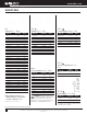
www.nibco.com AHEAD OF THE FLOW ® Copper Tube Fittings continued SOLDER JOINT SPECIFICATION 1. Soldering Clearance (between the outside of the tube and the inside diameter of the solder cup) and the Depth of the Solder Cup (into which the tube is inserted). Chart 1 – Soldering Clearance and Solder Cup Depth Nominal Size of Fitting (Inches) 1/4 3/8 1/2 5/8 3/4 1 1 1/4 1 1/2 2 (34.0) 2 1/2 (37.3) 3 (42.2) 3 1/2 4 5 (67.6) 6 Maximum I.D. of Fitting Inch (mm) 0.381 0.506 0.631 0.756 0.881 1.132 1.382 1.
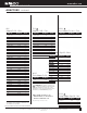
www.nibco.com BRAZING INFORMATION Copper Water Tube Size Brazing A Filler Required Acetylene Consumption Torch Tip (In Inches) Inches (mm) Drill Size No. C.F.H. (C.M.H.) 1/4 0.25 B (6.4) 54 15.9 (0.5) 3/8 0.38 B (9.7) 54 15.9 (0.5) 1/2 0.50 (12.7) 51 24.8 (0.7) 5/8 0.62 (15.7) 51 24.8 (0.7) 3/4 1.00 (25.0) 51 24.8 (0.7) 1 1.60 (41.0) 48 31.6 (0.9) 1 1/4 2.00 (51.0) 48 31.6 (0.9) 1 1/2 2.60 (66.0) 44 38.7 (1.1) 2 4.40 (112.0) 40 60.0 (1.7) 2 1/2 5.90 (150.0) 40 60.0 (1.7) 3 7.90 (200.0) 35 70.0 (2.
www.nibco.
www.nibco.
www.nibco.com AHEAD OF THE FLOW ® Copper Fittings Dimensional Data The mechanics of making both the solder joint and the brazing joint are comparatively similar. Complete instructions on proper techniques of both of these joining methods are outlined in this catalog on pages 46-48. A very important consideration in Copper Piping is the selection of the proper bonding medium. As a general rule, the working temperature of the installation is a more important consideration than the working pressures.
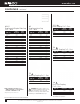
www.nibco.com DIMENSIONAL DATA – BRAZING FITTING ENDS Male End (Fitting Connector) Diameter Female End (Brazing Cup) Diameter Fitting End Solder Cup Length Length Nominal Min. Max. Min. Max. Min. Min. Water Tube Size (In Inches) Inch (mm) Inch (mm) Inch (mm) Inch (mm) Inch (mm) Inch (mm) 1/4 3/8 1/2 5/8 3/4 1 1 1/4 1 1/2 2 2 1/2 3 3 1/2 4 5 6 8 10 12 1 0.373 0.497 0.622 0.747 0.872 1.122 1.372 1.621 2.121 2.621 3.121 3.621 4.121 5.121 6.121 8.119 10.119 12.119 (9.47) (12.62) (15.80) (18.
www.nibco.com AHEAD OF THE FLOW ® EXPANSION AND CONTRACTION In the majority of low-pressure heating systems employing copper tube and installed in small houses or private dwellings, provision for expansion and contraction is relatively simple. Mains, risers, and branches to radiators should be free or floating at one end of the line.
www.nibco.com The Fine Art of Soldering When adjoining surfaces of copper and copper alloys meet under proper conditions of cleanliness and temperature, solder will make a perfect adhesion. The strength of joint is equal to or even greater than the strength of tube alone. Surface tension seals the joint. Capillary attraction draws solder into, around, and all about the joint. It’s easy to learn to make a perfect solder joint when you use NIBCO® Fittings.
www.nibco.com AHEAD OF THE FLOW ® The Fine Art of Brazing Best results will be obtained by a skilled operator employing the step-by-step brazing technique that follows: 1. The tube should be cut to desired length with a square cut, preferably in a square-end sawing vise. The cutting wheel of the type specifically designed for cutting copper tube will also do a satisfactory job.
www.nibco.com 7. Brazing is started by applying heat to the parts to be joined. The preferred method is by the oxyacetylene flame. Propane and other gases are sometimes used on smaller sizes. A slightly reducing flame should be used, with a slight feather on the inner blue cone; the outer portion of the flame, pale green. Heat the tube first, beginning at about one inch from the edge of the fitting. Sweep the flames around the tube in short strokes up and down at right angles to the run of the tube.
www.nibco.com AHEAD OF THE FLOW ® Frequently Asked Questions Q: A: What is the pressure rating of a given fitting? Fittings are rated per Table 1 of ASME B16.22. The system rated pressure shall be the lowest of the fitting, tube or joint. Q: A: When copper fails in a system, what is the problem? MOST COMMON: 1. Velocity – fluid is moving too fast. Recommendation: 2-3 fps (0.0508-0.0762 m/s) hot water 140°F, 5-8 fps (0.1270.2032 m/s) cold water. 2.
www.nibco.com 50 years NIBCO INC. 50 YEAR LIMITED WARRANTY Applicable to NIBCO INC. Copper Fittings NIBCO INC. warrants each NIBCO® copper fitting to be free from defects in material and workmanship under normal use and service for a period of fifty (50) years from the date of original installation.
www.nibco.com AHEAD OF THE FLOW ® Numerical Index Figure Number Page Figure Number Page 100 Series Cast Heavy Flared 101............................... 23 104............................... 23 624.............................. 633-W......................... 638.............................. 698.............................. 500 Series Cast Flared 500.............................. 24 501............................... 23 503.............................. 23 504..............................
www.nibco.com NOTES Visit our website for the most current information. 52 NIBCO INC. WORLD HEADQUARTERS • 1516 MIDDLEBURY ST. • ELKHART, IN 46516-4740 • USA • PH: 1.800.234.0227 TECH SERVICES PH: 1.888.446.4226 • FAX: 1.888.234.0557 • INTERNATIONAL OFFICE PH: +1.574.295.3327 • FAX: +1.574.295.3455 www.nibco.
www.nibco.com AHEAD OF THE FLOW ® NOTES Visit our website for the most current information. NIBCO INC. WORLD HEADQUARTERS • 1516 MIDDLEBURY ST. • ELKHART, IN 46516-4740 • USA • PH: 1.800.234.0227 TECH SERVICES PH: 1.888.446.4226 • FAX: 1.888.234.0557 • INTERNATIONAL OFFICE PH: +1.574.295.3327 • FAX: +1.574.295.3455 www.nibco.
www.nibco.com NOTES Visit our website for the most current information. 54 NIBCO INC. WORLD HEADQUARTERS • 1516 MIDDLEBURY ST. • ELKHART, IN 46516-4740 • USA • PH: 1.800.234.0227 TECH SERVICES PH: 1.888.446.4226 • FAX: 1.888.234.0557 • INTERNATIONAL OFFICE PH: +1.574.295.3327 • FAX: +1.574.295.3455 www.nibco.
globally connecting you at all levels It’s a new age of business, and a new way at NIBCO. From Elkhart, Indiana to Lodz, Poland, and points beyond, our company has integrated manufacturing, distribution, and networked communications to provide a seamless source of information and service, 24 hours a day, 7 days a week. But this integration hasn’t happened overnight. It’s been part of a long-term strategic World Headquarters process that has pushed us to reconsider every aspect of our business.
C-CF-0417 VALVES Pressure-rated bronze, iron and alloy-iron gate, globe and check valves • Pressurerated bronze ball valves • Boiler specialty valves • Commercial and industrial butterfly valves • Lined butterfly valves • Circuit balancing valves • Carbon and stainless steel ball valves • ANSI flanged steel ball valves • Lined ball valves • Pneumatic and electric actuators and controls • Grooved ball and butterfly valves • High performance butterfly valves • UL/FM fire protection valves • MSS specificatio