Instruction Manual PARAGON Series DVR
EVERFOCUS ELECTRONICS CORPORATION PARAGON Series DVR Instruction Manual 2009 EverFocus Electronics Corp www.everfocus.com All rights reserved. No part of the contents of this manual may be reproduced or transmitted in any form or by any means without written permission of the Everfocus Electronics Corporation. Release Date: July 2009 QuickTime is a registered trademark of the Apple Computer, Inc. Windows is a registered trademark of the Microsoft Corporation.
Safety Precautions • To avoid any damage, please consider the following safety warnings: • Never place the recorder near to heaters, furnaces, other heat sources or under direct solar irradiation. • Operate the device only in locations providing the tolerable operating temperature range 0°C~40°C/32°F ~ +104°F. • Make sure that the device‘s ventilation slots are not covered or sheeted. • For cleaning, make sure the device is plugged off and only use a damp cloth without acid detergent.
WEEE This Product is RoHS compliant. The information in this manual was current upon publication. The manufacturer reserves the right to revise and improve his products. Therefore, all specifications are subject to change without prior notice. Misprints reserved. Please read this manual carefully before installing and using this unit. Be sure to keep it handy for later reference.
TABLE OF CONTENTS 1 PRODUCT OVERVIEW ..................................................................................................... 1 1.1 1.2 1.3 1.4 1.5 2 FEATURES ....................................................................................................................... 1 PACKAGE CONTENTS................................................................................................... 2 SPECIFICATIONS ..................................................................................
4.2 4.3 4.4 4.5 LOGIN............................................................................................................................. 27 SELECT CAMERA OPERATION................................................................................. 28 PLAYBACK.................................................................................................................... 28 PTZ .........................................................................................................................
5.9 DISK SETTING .............................................................................................................. 76 5.9.1 5.9.2 Disk....................................................................................................................................................... 76 Lock/Format ......................................................................................................................................... 77 5.10 SYSTEM SETTING ................................
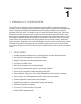
Chapter 1 1 PRODUCT OVERVIEW The latest EverFocus digital video recorder generation is based on MPEG-4 compression technology, resulting in enhanced recording capacity and improved network image transmission speed with high image quality. Comprehensive features and extended event recording settings enable the almost universal application of this DVR series. The Paragon Series DVR comes with multiple control inputs.
Audio recording capabilities* 2 Hot Swappable HDD or 4 internal HDD Built-in DVD burner* Support eSATA 2 USB 2.0 ports (located on front panel) for video archive and mouse usage Multi-language support Simultaneous VGA, composite and S-Video output Watermark capabilities to identify intentional modifications of recorded data Rack mountable *Feature not available for all models 1.
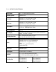
1.3 SPECIFICATIONS Video Format NTSC / PAL (auto detected by system) Operating System Embedded Linux Video Input EPARA16: 16 x 1 Vpp FBAS, BNC, 75 Ohm EPARA8: 8 x 1 Vpp FBAS, BNC, 75 Ohm Video Loop EPARA16: 16 x 1 Vpp FBAS, BNC, 75 Ohm EPARA8: 8 x 1 Vpp FBAS, BNC, 75 Ohm Video Output Main monitor: 1 Vpp FBAS, BNC at 75 Ohm 1 x VGA ( res.
Recording Modes Continuous, schedule, or event recording Playback Rate NTSC 352 x 240: 480 IPS 704 x 240: 240 IPS 704 x 480: 120 IPS Playback Search Function By time / date; by event (alarm / motion); Smart Motion Grid Search Motion Detection Adjustable by channel , 22x16 sensor fields each with 10 levels sensitivity Video Loss Detection Yes Event Log Maximum 500000 events Event Alarm Fan failure, hard disk failure, hard disk temperature over, hard disk full, HD off, power loss, record stop, ne
Ambient Temperature 0°C ~ 40°C ; 32°F ~ 104°F (20%~80% humidity) Remote Control Handheld IR remote control; RS-485 keyboard EKB-500 (optional) 5
1.4 FRONT PANEL Your primary interaction with your new DVR will be through the Front Panel buttons and their corresponding buttons on the included Remote Control. Take a moment to learn where the keys are as the remainder of the manual will refer to them often. Figure 1-1 Front Panel 1) 2 x USB-2.0 port for USB mouse, USB-Flash-Drive 2) Multiview Keys: 16x NOTE: 4x 9x 13x 10x PiP The LED will indicate the selected screen layout. The Multiview keys are only active in Main monitor - operation.
6) SEQ: 7) ZOOM: 2x electronical zoom. For details please consult chapter 4.11 ZOOM. NOTE: Sequence key for automatic switching of a defined camera sequence The Zoom key is only active in Full screen at Main monitor. 8/9) MONITOR: The MONITOR key switches operation between MAIN and CALL. The active screen will be Main monitor when LED is in “M” and Call monitor when LED is in “1”. For more details, please refer to Chapter 4.10 MONITOR .
Jog (inner wheel): Use Jog to scroll through and highlight individual cameras. In PAUSE mode, use the Jog to move frame by frame. Within menu functions, use the jog to adjust the values / parameters. Use either Shuttle or Jog to switch between MENU parameters. 24) POWER: LED indicating power on.
1.5 REAR PANEL During initial setup you will be connecting your DVR to multiple input and output devices. This is done through the rear panel. ○1 ○2 ○5 gdg ○6 ○3 ○4 10 ○ 11 ○ ○7 ○8 ○9 12 ○ Figure 1-2 Rear Panel ○1 POWER: Power socket for external power supply, 100~240VAC power source ○2 Audio output: Audio output ○3 Audio inputs: Audio inputs 1~16(1~8 for EPARA8) ○4 MAIN monitor: Main monitor output.
○7 Alarm inputs: 8 (EPARA8) or 16 (EPARA16) dry contact alarm inputs, programmable NO or NC in alarm menu. ○8 Alarm outputs: 4 NO/NC dry contact alarm outputs.
Chapter 2 2 INSTALLATION 2.1 VIDEO INPUTS/OUTPUTS INSTALLATION Cameras have to be connected using 75 Ohm video cable (e.g. RG-59, RG-12) and suitable BNC plugs. Due to inappropriate absorbability, 50 Ohm coax cable (e.g. RG58), antenna cable and further types of coax cable are not suitable.
All connected video sources must provide a 1 Vpp NTSC/EIA or PAL/CCIR standard video signal (depending on DVR version). When interconnecting transmission lines (twisted pair, fiber optics, radio) to the video inputs, make sure all receivers are accurately calibrated. The Main monitor can be connected to BNC, Composite, or VGA monitor output. NOTE: VGA monitor must support 800x600@60Hz resolution. For local DVR operation, Main monitor connection is required. Call monitor connection is optional.
2.2 AUDIO INSTALLATION The PARAGON DVR provides 16/8 audio inputs and 1 audio output. The inputs are designed for max. 1 Vpp @ 20 KOhm input. The installation has to be effected with audio coax cable and RCA plugs. The output provides a max. 1 Vpp @ 20 KOhm output line audio signal and may be connected to e.g. a monitor‘s audio input. The direct connection of (passive) speakers is not supported.
2.3 ALARM / CONTROL CONTACTS INSTALLATION The PARAGON alarm inputs can be used to start recording or adjust the current recording rate. Furthermore, alarm reactions such as camera switching, buzzer, e-mail, and network alarm are available, as well as 4 alarm output relays if required. Additionally the PARAGON DVR provides 4 x TTL - level control outputs with similar functionality as the relay outputs. 2.3.1 Alarm Input Contacts EPARA8 provides 8 alarm inputs, EPARA16 provides 16.
1. Playback: Playback is active as long the contact is closed. This function is helpful in combination with the "Quickplay" function ( chapter 5.4.3) CTRL IN CTRL IN GND GND Idle state 2. Record: Playback The input switches to Record (or Record Standby) as long the contact is closed. CTRL IN CTRL IN GND GND Idle state Record / Record Standby 3. Armed / Disarmed: If the contact is closed, the DVR will switch off alarm (alarm contact and motion alarm) operation.
2.4.1 General RS-485 bus installation The EKB-500 keyboard uses an RS-485 simplex wiring; the signal is transferred via a single twisted pair line. CAT5 network cable is recommended, UPT version (unshielded) is sufficient for normal application. A shielded cable should be used if the installed cables are expected to be highly susceptible to interferences. The number of devices installed in one bus is limited to 32, and the maximum cable length is 1200m.
An RS-485 distributor can also be used to increase the maximum number of devices on the bus as well as the total range. Each distributor output provides another RS-485 bus. This allows each output to extend an additional 1200m, and it also enables the additional connection of 31 further devices to each output (the output itself represents one device). The maximum system expandability depends on the RS-485 address range of the installed devices.
2.4.5 Speed Dome Installation Speed dome or telemetry receiver pan/tilt/zoom control is available through web browser or the optional PowerCon software if the DVR is connected to a network. Local telemetry control is provided by USB mouse control or by the optional EKB-500 keyboard. Supported protocols: EverFocus, Pelco-D, Pelco-P, Samsung, Transparent Required DVR settings: RS-485 receiver address in CAMERA menu ( chapter 5.10.4.) RS-485 parameters and protocol in the I/O CONTROL menu ( chapter 5.10.4.
2.7 NETWORK CONNECTION This section only describes physical connection to an Ethernet network. This step must be completed before the DVR can connect to the network. For details on setting up the DVR for network connection, see Chapter 5.10.4 Network Setup: LAN. There are two basic types of connection: 2.7.1 Direct PC Connection through Crossover Network Cable The point-to-point connection of DVR and PC requires a crossover (crossed) network cable.
Figure 2-2 Network Connection through Patch Cable Pinout of straight patchcable 2.8 FINAL INSTALL PROCESS Once you have completed the basic wiring connections, you are ready to turn on the DVR. Simply plug in the power source. The POWER LED will light up if power is normal. Once the system has finished loading, you can begin to set up the menu options for the DVR.
Chapter 3 3 MOUSE AND FRONT PANEL OPERATION Paragon series DVR supports multiple sources to control the DVR. It can be controlled with a mouse, the front panel, an EKB500, the handheld remote control, or serial command from RS232 port. This chapter will cover the basic operation using mouse and front panel. 3.1 GENERAL USB MOUSE OPERATION 3.1.1 How to select a channel / Enable audio 1. In a view consisting of more than one channel, user can select a channel by clicking once on desired channel screen.
3.1.3 Operation in Configuration Menu Click on the “Configuration” icon to bring up Configuration menu. NOTE: If password is active, you will need to log in first. Refer to “4.2 LOGIN” for information on logging in. The Main menu (shown in Figure 3-2 OSD Menu) is divided into 3 main sections. 1 ○ 2 ○ 3 ○ Figure 3-2 OSD Menu 1 In section 1, there are ten setup options available. Move the mouse over an icon and click to select it.
Button: Click the button to execute the function. Bar: Click and hold on the cursor to adjust the bar Left or Right. * Note about on-screen keyboard: Click on a key to input that character.
3.2 GENERAL FRONT PANEL OPERATION 3.2.1 Front Panel Key Review The basic principle of front panel operation is to use Jog and Shuttle to navigate among the menu items. Use “Enter” key to confirm a selection or enter the next level menu. Press “Menu” key to enter the Main Menu or exit from the current level of the menu. 3.2.2 How to select a channel / Enable audio 1. In a view consisting of more than one channel, turning Jog or Shuttle can scroll through each channel that is displayed.
1 ○ 2 ○ 3 ○ Figure 3-3 (OSD Menu) 1 In section 1, there are ten setup options available. Use Jog or Shuttle to highlight an icon and press ○ “Enter” to select it. 2 In section 2, the main options for the selected icon will be displayed. Use Jog to highlight an option and ○ press “Enter” to select it. 3 In section 3, all the details for the selected option will be available here. Use Jog to move between items ○ and press “Enter” to make changes.
Bar: Press “Enter” key to activate the slider, then use Jog to adjust the setting. Press “Enter” again to finalize the changes. * Note about on-screen keyboard: Use Jog to move up and down. Use Shuttle to move left and right. Press Enter on a key to input that character.
Chapter 4 4 GENERAL DVR OPERATIONS This chapter introduces the operations on major functions including playback, layout change, sequence, triplex operations, copy, and search. 4.1 RECORD By default, the Paragon series DVR will always be in record mode. When the DVR is turned on, it will start to record. The exceptions are: 1. Paragon DVR will not record any uninstalled cameras (Refer to section 5.3.1 for more detail) 2. If a schedule is active, Paragon DVR will follow the record settings of the schedule.
+ To input password by mouse: click the password field to bring up the on-screen keyboard (see Figure 4-2 On-screen Keyboard). Click on each button to input the desired characters for the password. When finished, click “Done” on the on-screen keyboard to confirm the password. + To input password using front panel: press “Enter” key to show the on-screen keyboard (see Figure 4-2 On-screen Keyboard).
A playback bar will show as the figure below: 1 2 3 4 9 5 6 7 8 2009/05/25 09:09:30PM 10 11 13 2009/05/25 09:09:40PM 14 15 12 10 10 2009/05/25 09:10:30PM 16 1. Stop key: press to stop playback 2. Slow Reverse key: press to slow reverse playback 3. Pause key: press to pause playback 4. Slow Forward key: press to slow forward playback 5. Fast Reverse key: press to fast reverse playback 6. Reverse key: press to reverse playback 7. Forward key: press to forward playback 8.
4.5 PTZ 4.5.1 General PTZ control Right-click to bring up the menu bar and click on to enter PTZ Menu. The following actions can be performed using the PTZ Menu: 1. Use Direction Arrows (up, down, left, right) to move the camera to the desired direction and angle. 2. In Zoom option, Click “Z+” to zoom closer or “Z-” to zoom farther away. 3. In Focus option, click “F+” to increase the focus or click “F-” to decrease the focus. 4.
Click “C” to clear the digit in cell Click “X” at top-right corner to close PTZ menu. Click “Exit” to leave PTZ function. 4.5.2 Express control PTZ When PTZ menu is closed, the mouse cursor will change to a different icon in different areas of the screen. User can control PTZ direction, zoom, and focus by clicking directly on screen. 1 2 3 4 5 Focus + 6 Zoom + 7 8 9 Focus - 10 Zoom - 11 12 15 16 13 14 Figure 4-3 Express Control PTZ The screen is divided into a 4x4 grid.
4.6 LAYOUT The Paragon DVR has a total of seven display modes available. The different available layouts are shown below: (Full screen) (PIP) (10 screens) (4 screens) (13 screens) (9 screens) (16 screens) NOTE: PIP display is not available in Playback mode To change layout, follow the steps below: By mouse: Right-click to bring up the menu bar and click to scroll through each display option.
4.7 CHANNEL SWITCHING Use this function to change channel position 1. Select one camera 2. Press Channel button . 3. Click on the channel number you wish to switch on channel bar. The display of channel will be switched. EX: Select camera1 and enter Channel menu and choose “2”, than camera1 will show on position of camera2, camera2 will show on position of camera1 4.8 DISPLAY 1. Press Display button on menu by using mouse or press “Display” button on the front panel. 2.
4.9 SEQUENCE 1. By mouse: Click Sequence button to enter the auto sequential switching mode. 2. By front panel: Click Sequence button on front panel to enter the auto sequential switching mode. 4.10 MONITOR The DVR can connect to main monitor and call monitor simultaneously, but only one of them can be controlled at one time. This feature allows user to switch control between two monitors.
4. When in ZOOM mode, the mouse cursor will change to a different icon in different areas of the screen. User can control PTZ direction, zoom, and focus by clicking directly on screen: 1 2 3 4 5 6 7 8 9 10 11 12 13 14 15 16 Figure 4-4 Zoom Express Control The screen is divided into a 4x4 grid.
4.12.1 Time Search Figure 4-5 Search Menu – Time Search Play From: Select the time to be searched by choosing the Date and Time. Click on the “Play” button to start search. The DVR will automatically play the video starting at the selected time. DVR will play the next available time if there is no data in selected time. In search playback mode, press stop button to come back to search menu. 4.12.
From: Select starting date and time To: Select ending date and time. Camera: Select which cameras to search for. Event: Select which event type(s) to search for. Choose from Alarm, Motion, Video Loss, or Others. Click on the “Search” button to start searching. The search results will be shown as a list of events. Prev Page: Go to previous page.
4.12.3 Motion Search In order to perform a Motion Search, motion must be enabled first (see “Chapter 5.3.3”). Figure 4-7 Search Menu – Motion Search From: Select motion search starting date/time. To: Select motion search ending date/time. Camera: Select camera number to be searched.
Grid Setting: Choose which areas of the motion grid will be included in the search. The areas you set in motion search must also be active in the motion settings of the Camera Setting Menu. Use the mouse to drag your desired area. Press “Set All” button to select the entire area. Press “Clear All” to deselect the entire area. Press “Save & Back” to save the motion grid setting and return to Motion Search menu. Press “Cancel” to cancel. Press “Search” button to start searching. 4.
Archive To: Select whether you want to copy to USB or DVD. Data Size: Shows the estimated total size for the selected time period. (Because the Paragon is Linux based, you may notice a slight size difference in the file between DVR and PC) Archive Now: Press “Archive” button to start archiving. 4.14 LOGOUT Right-click to bring up the menu bar and click (see Figure 4-10).
Chapter 5 5 DVR CONFIGURATION This chapter will walk you through the DVR Menu Settings step by step and show you how to set the DVR for your specific application. 5.1 CONFIGURATION MENU 1. To bring up the Main Menu, press the “Menu/Esc” key on the front panel or right-click with the USB mouse to bring up the OSD menu bar. 2. Press “Enter” or left-click on the “Configuration” icon “ ” to enter configuration menu. 5.2 EXPRESS Figure 5-1 Express Menu is a screen shot of the EXPRESS SETTING MENU.
Date: Set the current date of DVR. Time: Set the current time of DVR. Resolution: Select recording resolution based on video format. NTSC: 704x480 / 704x240 / 352x240 PAL: 704x576 / 704x288 / 352x288 Record Mode: Blank: No change for Record Mode Normal+Event: Normal recording plus event recording. Event Only: Event recording only. Schedule Rec: Schedule recording. Record With: Blank: No change for Record With Max. Recording Days: Set the maximum recording days.
DHCP: DHCP server in LAN will automatically assign IP for network connection. PPPoE: For direct DSL connection ONLY. Check with your ISP if they use PPPoE. IP Address: This field shows the current IP Address for the DVR. A Fixed IP address must be set manually. If DHCP or PPPoE is selected, this value will be assigned automatically. Subnet Mask: This field shows the subnet mask for your network so the DVR will be recognized within the network.
5.3.1 Basic Setting Camera: Select the camera number. Title: The title setting allows you to assign a title to selected camera. Each title supports up to 16 characters. The on-screen keyboard will appear when you click the title option. Install: Check the box to enable the current camera. To take full advantage of the DVR’s recording abilities, any unused cameras should be disabled. Covert: Check the box to hide the camera picture in live and sequence modes.
PTZ ID: When using a PTZ Camera, this ID must match the ID used by the connected camera in order to control the camera using the DVR. Click “Done” to confirm selection, “Cancel” to cancel selection. Apply To: This button can be used to copy the recording settings to other cameras. Select which cameras you wish to copy to. "Select All" selects all cameras, “Unselect All” deselects all cameras. Click “OK” to copy the settings or "Cancel" to exit without copying. 5.3.
Apply To: This button can be used to copy the video settings to other cameras. Select which cameras you wish to copy to. "Select All" selects all cameras, “Unselect All” deselects all cameras. Click “OK” to copy the settings or "Cancel" to exit without copying. 5.3.3 Motion Figure 5-4 Camera Menu – Motion Camera: Select the camera you wish to adjust. “Title” will change to the title name of the selected camera. Enable: Check box to enable motion detection.
No change: No change on the call monitor display. Full screen: A full screen of the active camera will display on the call monitor. Pre-alarm Record: Check box to record several moments before the motion event. (Pre-alarm recording rate will follow “Normal” frame rate setting) Buzzer: Check box to enable buzzer when a motion event is triggered. Email Notify: Check box to send email notification when a motion event is detected.
Figure 5-5 Camera Menu – Motion Grid Setting Apply To: This button can be used to copy the motion settings to other cameras. Select which cameras you wish to copy to. "Select All" selects all cameras, “Unselect All” deselects all cameras. Click “OK” to copy the settings or "Cancel" to exit without copying.
5.3.4 Video Loss Figure 5-6 Camera Menu – Video Loss Camera: Select the camera you wish to adjust, “Title” will change to the title name of the selected camera. Enable: Check box to enable Video Loss. Log: Check box to record video loss events in the log. Pre-alarm Record: Check box to record several moments before the video loss. (Pre-alarm recording rate will follow “Normal” frame rate setting) Buzzer: Check box to enable buzzer when a video loss event occurs.
Apply To: This button can be used to copy the video loss settings to other cameras. Select which cameras you wish to copy to. "Select All" selects all cameras, “Unselect All” deselects all cameras. Click “OK” to copy the settings or "Cancel" to exit without copying. 5.4 RECORD & PLAY SETTING Figure 5-7 is a screen shot of the RECORD & PLAY SETTING MENU. This menu is used to configure basic recording and playback settings. Figure 5-7 Record & Play Menu 5.4.
Time Stamp: Select if the time and date will display while recording. Choose from Top, Bottom, or Off. Record Status Relay Output: Select from “NONE”, “1”, “2”, “3”, or “4”. Auto Erase Video: The hard drive will automatically erase after the selected number of days. To use the maximum hard drive space, choose “OFF”. 5.4.2 Built-in Cal. The built-in recording calculator can give a rough estimation of the total recording time of the DVR with current settings. Figure 5-8 Record & Play Menu-Built-in Cal.
5.4.3 Play Figure 5-9 Record & Play Menu - Play Quick Playback: Check the box to enable quick playback function. Playback From X Seconds ago: When the DVR is put into playback, it will begin playing from the selected time. Choose from 60 to 3600 seconds.
5.5 ALARM & EVENT SETTING is a screen shot of the ALARM & EVENT SETTING MENU. This menu will walk you through alarm and event setup. Figure 5-10 Figure 5-10 Alarm & Event Menu - Alarm 5.5.1 Alarm Alarm: Select the alarm number from 1 to 16. Enable: Check box to enable alarm. Log: Check box to record alarm events in the log. Pre-alarm Record: Check box to record several moments before the alarm event.
Recording: Select which cameras will start recording when alarm happens. Email Notify: Check box to enable email notification when an alarm occurs. Input Type: This field is to change the type of alarm trigger. N.O.: Normal Open contact. N.C.: Normal Close contact. Network Alarm: Check box to send out a network alarm to client PC when motion occurs. (requires PowerCon software and setting up Alarm Server in Network Setup menu) Active Camera: This field is for assigning the alarm to a specific camera.
5.5.2 Event This section covers internal system event warnings. Figure 5-11 Alarm & Event Menu – Event Event: Select from the following event types. Fan Failure: The internal fans are equipped with rotation detection. Any fault of a fan will cause "Fan Failure" event. HD Temperature: Hard drive is over the safety warning temperature HD Failure: If DVR fails to detect a HDD on start up, the system will create a HD failure event.
Fan Failure: Figure 5-12 Alarm & Event Menu – Event-Fan Failure Log: Check box to record events in the log. Buzzer: Check box to enable buzzer when a fan fails to work. Email Notify: Check box to enable email notification when a fan fails to work. Network Alarm: Check box to send out a network alarm to client PC. (requires PowerCon software and setting up Alarm Server in Network Setup menu) Alarm Output: This will transmit a signal through one of the alarm outputs.
HD Temperature: Figure 5-13 Alarm & Event Menu – Event - HD Temperature Log: Check box to record events in the log. Buzzer: Check box to enable buzzer when hard drive’s temperature is over the “Temp. Warning Limit”. Email Notify: Check box to enable email notification when temperature is over the “Temp. Warning Limit”. Network Alarm: Check box to send out a network alarm to client PC.
HD Failure: Figure 5-14 Alarm & Event Menu – Event - HD Failure Log: Check box to record events in the log. Buzzer: Check box to enable buzzer when hard drive fails. Email Notify: Check box to enable email notification function when HD fails. Network Alarm: Check box to send out a network alarm to client PC. (requires PowerCon software and setting up Alarm Server in Network Setup menu) Alarm Output: This will transmit a signal through one of the alarm outputs.
HD Full: Figure 5-15 Alarm & Event Menu – Event - HD Full Buzzer: Check box to enable buzzer when hard drive is full. Email Notify: Check box to enable email notification when HD is full. Network Alarm: Check box to send out a network alarm to client PC. (requires PowerCon software and setting up Alarm Server in Network Setup menu) Alarm Output: This will transmit a signal through one of the alarm outputs. It can be set to either “NONE” (not active), “1”, “2”, “3”, or “4”.
HD Off: Figure 5-16 Alarm & Event Menu – Event - HD Off Buzzer: Check box to enable buzzer when hard drive is removed or turned off. Email Notify: Check box to enable email notification when HD is off. Network Alarm: Check box to send out a network alarm to client PC. (requires PowerCon software and setting up Alarm Server in Network Setup menu) Alarm Output: This will transmit a signal through one of the alarm outputs. It can be set to either “NONE” (not active), “1”, “2”, “3”, or “4”.
Power Loss: Figure 5-17 Alarm & Event Menu – Event – Power Loss Log: LOG is permanently checked for this feature. Power Loss events are always recorded by the DVR. Email Notify: Check box to enable email notification when HD is off. Network Alarm: Check box to send out a network alarm to client PC.
Record Stop: Figure 5-18 Alarm & Event Menu – Event – Record Stop Log: Check box to record events in the log. Buzzer: Check box to enable buzzer when DVR stops recording. Email Notify: Check box to enable email notification when DVR stops recording. Network Alarm: Check box to send out a network alarm to client PC. (requires PowerCon software and setting up Alarm Server in Network Setup menu) Alarm Output: This will transmit a signal through one of the alarm outputs.
Network Loss: Figure 5-19 Alarm & Event Menu – Event – Network Loss Log: Check box to record events in the log. Buzzer: Check box to enable buzzer when network is lost. Alarm Output: This will transmit a signal through one of the alarm outputs. It can be set to either “NONE” (not active), “1”, “2”, “3”, or “4”. Output Type: Output action when alarm is triggered. Timeout: Alarm output lasts for the set time duration. Permanent: Alarm will be continuously active until user presses “Enter” key.
5.6 SCHEDULE SETTING is a screen shot of the SCHEDULE SETTING MENU. In this menu you can set a unique timer to start recording during a specified time period. This menu is used to configure Express Setup, Holidays and Schedule settings. Figure 5-20 Figure 5-20 Schedule Menu-Express Setup 5.6.1 Express Setup Weekend Starts: Select day and time when weekend starts. Weekend End: Select day and time when weekend ends. Daytime Starts: Select daytime starting time.
Event Action: Check this box to enable Buzzer, Alarm out, E-mail and Network actions when an event occurs on the selected time period. Apply: Press Apply button bring up a confirmation window. Select “Yes” to confirm and apply express schedule settings or “No” to cancel changes. 5.6.2 Holidays In addition to setting a weekly record schedule, user can also schedule recording for specific days of the year. Figure 5-21 Schedule Menu-Holidays Data Type: Select either Holiday or Others.
Month/weekday: Repeats recording on a specific day of the month/week. Details: Specifies the date to be recorded. Prev: Previous Page (30 Holidays Total) Next: Next Page (30 Holidays Total) 5.6.3 Schedule Figure 5-22 Schedule Menu-Schedule Camera: Select a number to change the schedule for that camera. Each camera can be set on a 24 hour time block for Holiday (Hol), Other (Oth), Sunday (Sun), Monday (Mon), Tuesday (Tue), Wednesday (Wed), Thursday (Thu), Friday (Fri), or Saturday (Sat).
Schedule Setting using Front Panel 1. Enter schedule setting mode: press Enter button to enter schedule setting mode. At this time, the whole editing area at right-down side will be highlighted with a light blue frame. See below image. 2. Enter camera selection mode: turn Jog wheel to switch to Camera selection mode. When Camera selection mode is selected, all 16 cameras will be highlighted in a light blue frame. See below image. 3. Selecting camera: Turn Shuttle knob to select which camera to configure.
6. Editing blocks in a time bar: when a time bar is selected (highlighted in red frame), press Enter button, then the first block of this bar will be highlighted in blue. Turn Jog wheel to select the desired starting block. Press Enter button to cycle through the colors (gray > orange > blue). Move to a different block and repeat until each section has the desired color.
Normal: Record rate in frames per second (FPS) for continuous recording. The speed is limited to the maximum recording rate of the DVR divided by the number of installed cameras. Event Speed: Record rate in frames per second (FPS) for event recording. Event record speed can be set from 1 to 30 (25 for PAL). Action: Check this box to enable Buzzer, Alarm out, E-mail, and Network when an event occurs. Apply: Press this button to save settings and return to Schedule Menu.
5.7 NETWORK SETTING is a screen shot of the NETWORK SETTING MENU. This menu is for configuring the DVR for a network connection. Figure 5-24 NOTE: Since every Network Configuration is different, please check with your Network Administrator or ISP to see if your DVR requires specific IP addresses and/or port numbers. Figure 5-24 Network Menu – LAN 5.7.1 LAN Network Type: Static IP: User can set a fixed IP for network connection.
5.7.2 EMAIL Figure 5-25 Network Menu – Email SMTP Server: Assign the SMTP (e-mail) server’s name. NOTE: For more reliable email service, use the server’s IP address. SMTP Port: Assign the port number used by the SMTP server. Authentication: Check this box if the SMTP server requires authentication (user name / password). SSL: Check the box if mail server needs to be encrypted by SSL. User name: Input the login user name if the SMTP server requires authentication.
EverfocusDDNS Figure 5-26 EverfocusDDNS DVR Name: Input the desired name for the DVR Register/Update: Click the button to submit and register the name to the Everfocus server. www.dyndns.org Figure 5-27 www.dyndns.org Host name: Host name created through the dyndns account. User name: User name of the dyndns account.
Password: Password of the dyndns account. Confirm: Re-enter password. Note: For more details on DDNS setup, please see “Chapter 8 - Everfocus DDNS Setup”. 5.7.4 Alarm Server Figure 5-28 Network Menu – Alarm Server Server IP1~3: IP address of client PC with installed PowerCon Software. The network alarm can be transmitted to up to 3 addresses.
5.8 DISPLAY SETTING is a screen shot of the DISPLAY SETTING MENU. This menu will walk you through Monitor OnScreen Display (OSD) and Sequential setup. Figure 5-29 Figure 5-29 Display Menu – Monitor OSD 5.8.1 Monitor OSD These are the display options for the Main Monitor. Main Monitor Camera Title: Check the box to display camera titles. Date/Time: Check the box to display current date/time. Playback Date/Time: Check the box to display playback date/time.
5.8.2 Main M/T SEQ Figure 5-30 Display Menu – Main M/T SEQ Step: Sequence order. Cannot be changed. Camera: Select which camera appears on the current step. Dwell (sec): Set the dwell time for each step. Sequence dwell time can be set from 0 to 99 seconds. 5.8.3 Call M/T SEQ Figure 5-31 Display Menu – Call M/T SEQ Step: Sequence order. Cannot be changed. Camera: Select which camera appears on the current step. Dwell (sec): Set the dwell time for each step.
5.9 DISK SETTING is a screen shot of the DISK SETTING MENU. This menu is used to review and manage the DVR’s hard drive settings. Figure 5-32 Figure 5-32 Disk Menu 5.9.1 Disk Disk: Select the disk number. Health Status: Displays current status of the selected disk. Disk Temperature: Displays current disk temperature. Disk Size/Total: Shows total disk size. Disk Size/Usage: Shows percentage of used disk space.
5.9.2 Lock/Format Figure 5-33 Lock/Format Menu Maximum Lock (%): User can set the maximum lock percentage of the HDD volume. After setting lock percentage, it can be enabled/disabled in three places 1. “Camera > Basic Setting > Motion > Auto Lock” 2. “Alarm & Event > Alarm > Auto Lock”. 3. Lock or unlock the file manually in search result list Current Lock (%): Displays the current lock percentage of HDD volume. If locked data has reached the maximum lock percentage, it will stop locking new data.
5.10 SYSTEM SETTING is a screen shot of the SYSTEM SETTING MENU. This menu is for setting up the system configurations of the DVR. Figure 5-34 Figure 5-34 System Menu – Date/Time 5.10.1 Date/Time Date: Set current Date. Time: Set current Time. Date Format: Choose date format from yyyy/mm/dd, dd/mm/yyyy, or mm/dd/yyyy. Time Format: Change time format between 12H and 24H mode. Time Zone: Set the time zone that the DVR adjusts to when updating from the time server.
5.10.2 Daylight Saving Figure 5-35 System Menu – Daylight Saving Daylight Saving: Check the box to enable daylight saving time. Start Date: Set the start date of daylight saving time. Start Time (hh:mm): Set the time when daylight saving time begins. Set To (hh:mm): This is what the time will change to when daylight saving begins. For most regions, this will be one hour ahead of the “Start Time”. End Date: Set the end date of daylight saving time.
5.10.3 User User Menu is where you can add or delete different users on the system as well as set administrator rights. Figure 5-36 System Menu – User Add Click “Add” button to add a new user. Set the name (case-sensitive), password, and access level. Press “Add” button to confirm a new user or “Cancel” to exit without making changes.
Edit Click “Edit” button to make changes to an existing user account. Press “Save” button to save changes or “Cancel” to exit without making changes. Figure 5-38 System Menu – User - Edit Delete Click “Delete” button to remove the selected user account. A pop-up window will ask for confirmation. Choose “Yes” to delete user or “No” to cancel. User Login: Check this box to activate user login.
5.10.4 I/O Control is a screen shot of the I/O Control Setting Menu. This menu is used to define the settings for controlling the DVR through RS232 or RS485. Figure 5-39 Figure 5-39 System Menu – I/O Control RS232 Baud Rate: The speed used to transmit instruction or information through the RS232 port on the DVR. Choose from the following speeds: 1200, 2400, 4800, 9600, 19200, 38400, 57600, or 115200 BPS. Data Bit: The data bit used for transferring. This can be set to 8 or 7.
5.10.5 Misc. Figure 5-40 System Menu – Firmware & Misc. Firmware Current Firmware Version: Displays the current version. Firmware Upgrade: Press “Upgrade” to upgrade the firmware. NOTE: To perform a Firmware Upgrade, you will need to connect a USB flash device with the latest version of the firmware. Do not disconnect USB device or turn off the power of the unit during the upgrade; this can cause the system to crash.
5.11 INFORMATION SETTING is a screen shot of the INFORMATION SETTING MENU. This menu displays important system information. Figure 5-41 Figure 5-41 Information Menu – System 5.11.1 System System Version: Displays firmware version number. Model: Displays DVR model number. NTSC/PAL: Displays current video format. Network IP: Displays the DVR’s current IP Address. MAC: Unique address of the DVR’s internal network card. This option cannot be changed.
5.11.2 Log Figure 5-42 Information Menu – Log Log Type: Configurations: to see log sorted by setting changes Event: to see log sorted by event Record: to see log sorted recording start/stop Operation: to see log sorted by operation User: to see log sorted by user login View Log: Press “View Log” button to view the log. See Figure 5-43 for more detail. Clear Log: Press “Clear Log” button to clear the log. Export Log to USB: Export log data to USB.
Figure 5-43 Log List Prev Page: Go to the previous page of log. Next Page: Go to the next page of log.
Chapter 6 6 Networking Overview This chapter will give you a basic instruction on how to set up the DVR for network connection. It is highly recommended that you have a working knowledge of what a network is and how it works. This will be helpful in completing the networking process. 6.1 Introduction to TCP/IP TCP/IP is the group of protocols used by the Internet and most Local Area Networks (LANs) throughout the world.
6.4 Virtual Ports A port number represents a "channel" or entryway for network communications. Port numbers allow different applications on the same computer to utilize network resources without interfering with each other. Port numbers most commonly appear in network programming, particularly socket programming. Sometimes, though, port numbers are made visible to the casual user. For example, some websites on the Internet use a URL like the following: http://www.fakeaddress.
Do you have a static IP address? ______________ A Static IP address means you use the same IP address every time you connect to the Internet. With a static IP address, other Internet users always know the address of your location and can easily connect with it. This makes it much simpler to host a website, email server, or other type of server connection. Everfocus suggests using a static IP address. If this is not available, you will need to use a dynamic IP address. This is explained below.
6.7 Simple One to One Connection Crossover Ethernet Cable Pin outs: The Figure below shows the pin configurations for a cross-over cable. Connection Procedure: The First step is to purchase or make a cross-over cable. We recommend purchasing one if you have never made a cross-over cable.
Assign an IP of 192.168.001.003, a Subnet Mask of 255.255.255.000, and a Gateway of 192.168.001.001. You can ignore DNS Server. The next step is to set the computer’s network settings to match those of the DVR. You will need Administrator privileges on your Windows machine to do this. To assign a fixed IP address in Windows 2000/XP.
92
93
Click on the option that says “Use the following IP address” Assign an IP address of 192.168.1.2, a Subnet Mask of 255.255.255.0, and a Default Gateway of 192.168.1.1, then click OK. Restart both the computer and the DVR. To access the DVR from the computer, simply open Internet Explorer and in the address bar type: http://192.168.1.
6.8 Direct High Speed Modem Connection Straight Through Ethernet Cable Pin outs: The Figure below shows the pin configurations for a straight cable. Connection Procedure: The first step is to purchase or make a straight through cable. We recommend purchasing one if you have never made a straight through cable.
Once you have a straight through cable plug one end into the LAN port on the back of the recorder and the other into the high speed modem. Log into the EverFocus DVR menu and go to the Network Setting Menu. Input the Static IP address, the Subnet Mask, and the Gateway that you obtained from the internet service provider. Note: If you have a dynamic IP address, you can set the DVR to DHCP to automatically detect the network settings settings. Therefore, it can use a dynamic IP address.
6.9 Router or LAN Connection Straight Through Ethernet Cable Pin outs: The Figure below shows the pin configurations for a straight cable. Connection Procedure: The First step is to purchase or make a straight through cable. We recommend purchasing one if you have never made a straight through cable.
Once you have a straight through cable plug one end into the LAN port on the back of the recorder and the other into the router. Log into the EverFocus DVR menu and go to the Network Setting Menu. To let the router automatically assign an address: Set the Network Type to DHCP. Make sure to write down the IP address and the Gateway. Exit from the Menu to save settings. To manually assign an address: Go to a computer connected on the same network as the DVR.
number of the IP address. For example, if the IP address of the computer is 192.168.2.101, the DVR’s IP address should be 192.168.002.050. To access the DVR from a computer simply open Internet Explorer and in the address bar type: http:// (IP address of the DVR) Note: The DVR’s IP address will only work at the location of the DVR. To connect from a different location over the Internet, see below. To set DVR for Internet Connection through router The next step is to open ports within your router.
Chapter 7 7 REMOTE OPERATION FROM BROWSER 7.1 CONNECTING TO PARAGON To access the DVR from a computer, open an Internet Explorer window and in the address bar type: Local connection: http:// (IP address from the DVR’s Network Menu) Internet connection: http:// (IP address given by your Internet Service Provider) The login page will appear on the screen similar to the one shown above. Enter a user name and password to access the recorder. These can be changed in the System section of the Main Menu.
7.2 BROWSER SECURITY SETTING 7.2.1 Installing ActiveX controls When you first connect to the DVR’s IP address, you may see a screen like the one below. If you do not see a yellow bar like the one the arrow is pointing at, your security settings may be too high. If so, go to “Section 7.2.2 - Enabling ActiveX Controls.
Install the ePlusDVR.cab file when prompted to do so. Once the file finishes installing, you will return to the same login page as before. Type in the username and password and click Login to view the cameras.
7.2.2 Enabling ActiveX Controls Note: This section is only necessary if you DO NOT see the yellow ActiveX bar at the top of your browser screen when you first connect to the DVR. At the top of the Internet Explorer Window, click on Tools, then select Internet Options. Click the Security tab at the top of the window, then choose Custom Level near the bottom.
In the Security Settings window, scroll to “ActiveX controls and plug-ins” Set the controls as follows: “Enable”: Allow previously unused ActiveX controls to run without prompt (Internet Explorer 7 only) Allow scriptlets (IE7 only) Automatic prompting for ActiveX controls Binary and script behaviors Display video and animation on a webpage that does not use external media player (IE7 only) Run ActiveX controls and plug-ins Script ActiveX controls marked safe for scripting “Prompt”: Download
Close the window so you are back at the login screen. Click the Refresh button to reload the page. Install the ePlusDVR.cab file when prompted to do so. Once the file finishes installing, you will return to the same login page as before. Type in the user name and password and click Login to view the cameras. Default user name: admin Default password: 11111111.
7.3 REMOTE LIVE VIEW 3 2 1 1. In the main page, you will see live images in a 16-screen display (or 8 screens, depending on the model). 2. The status of each camera is represented by different colors on the left side of the screen. Green means normal; orange indicates a Motion; blue indicates Vloss, red indicates an alarm event. Click on a camera number to switch that camera to full screen. Click on “4UP”, “9UP”, or “16UP” to display 4, 9, or 16 screens.
7.4 REMOTE PTZ CONTROL 1. Use Direction Arrows (up, down, left, right) to move the camera to the desired direction and angle. 2. In Zoom option, Click “Z+” to zoom closer or “Z-” to zoom farther away. 3. In Focus option, click “F+” to increase the focus or click “F-” to decrease the focus. 4. In Iris option, you can increase the amount of light by clicking “I+” or decrease it by clicking “I-“. 5. To program a preset position a. Move PTZ camera to the specified position b. Click “Preset” button c.
11. Steps to run a tour a. Click “Tour” button b. Click the number of the desired tour c. Click “Go” button 12. Steps to remove a tour a. Click “Tour” button b. Click the number of the desired tour c.
7.5 REMOTE PLAYBACK To playback the video, press “Search” button. Select from “Time Search”, “Event Search”, or “Motion Search”. For more details about Search setting, please refer to “4.12 Search Setting”. “Event Search” and “Motion Search” will show maximum 400 search result items (from start time) Playback Control Keys Playback Control Keys: 1. Fast Rewind 2. Play Reverse 3. Stop Playback 4. Play Forward 5. Fast Forward 6.
Chapter 8 8 EVERFOCUS DDNS SETUP Setup Steps: Step 1. Set up the Network Menu according to the instructions detailed in the Networking chapter. (Make sure that DNS Server 1 is set correctly or DDNS will not work) Step 2. Go to the website http://everfocusddns.com and check for an available name. Note: This step is optional, as it is only used to check the availability of host name. If the name is available, proceed to step 3 for DDNS setup. Step 3. In DVR’s Network Menu, go to DDNS.
Chapter 9 9 LINKSYS & D-LINK PORT FORWARDING 9.1 LINKSYS PORT FORWARDING This section will cover a few simple configurations for the Linksys router. This chapter is only to offer some help to the installer and end user. Please understand we DO NOT support this product and will not give tech support on it. If you need additional technical support on this router you must call Linksys. To access the Web-based Utility, launch a web browser and type the Router’s default IP address, 192.168.1.
Applications and Gaming allows you to set up public services on your network, such as web servers, ftp servers, e-mail servers, or other specialized Internet applications. (Some Internet applications may not require any forwarding) To forward a port, enter the information on each line for the criteria required. Descriptions of each criterion are described here. Application - In this field, enter the name you wish to give the application.
9.2 D-LINK PORT FORWARDING This section will cover a few simple configurations for the D-Link router. This chapter is only to offer some help to the installer and end user. Please understand we DO NOT support this product and will not give tech support on it. If you need additional technical support on this router you must call D-Link. Whenever you want to configure your network or the DI-624, you can access the Configuration Menu by opening a web-browser and typing in the IP Address of the DI-264.
Click Virtual Servers on the left to bring up the following screen. Virtual Servers allows users who are connecting remotely to access services on the router’s Local Network. The functions of each field are described below. Virtual Server - Select Enabled or Disabled Name - Enter the name referencing the virtual service Private IP - The IP address of the device running the local services. Protocol Type - The protocol used for the virtual service.
Here is an example of the information for each service: Name HTTP CTRL Private IP 192.168.1.50 192.168.1.50 Protocol Both Both Private Port 80 1600 Public Port 80 1600 Schedule Enable Enable Note: If you changed port 80 in the DVR’s Network Menu, open that port instead of 80.
Chapter 10 10 TROUBLESHOOTING If you have problems with the system, run through the following checklist to see if you can solve the problem. The DVR will not go into record mode. Bring up the DVR’s Menu and check under the Camera Menu. Verify that all connected cameras are checked as “Installed”. Also, verify that Record Mode is set to “Normal + Event” for all cameras. Check the Disk or Information Menus and verify that the internal hard drive is being detected.
Appendix A APPENDIX A: TIMING OF ALARM MODES Transparent Mode Input Event Alarm Duration t t Event = t Reaction t Event: t reaction: Duration of alarm input source (motion, contact, system events...) Resulting duration for this alarm mode, related to event record, alarm outputs, OSD message, buzzer Timeout + Transparent Mode Input Event Alarm Duration t Event t Duration t t Reaction t Event: t Duration: t reaction: Duration of alarm input source (motion, contact, system events...
Timeout Mode Input Event Alarm Duration t t Event t Duration = t Reaction t Event: t Duration: t reaction: Duration of alarm input source (motion, contact, system events...
Timeout Mode: Retrigger of Alarms t Event: t Duration: t reaction: Duration of alarm input source (motion, contact, system events...) Alarm duration for timeout, defined in the event setup menus Resulting duration for this alarm mode, related to event record, alarm outputs, OSD message, buzzer Timeout+Transparent Mode: Retrigger of Alarms t Event: Duration of alarm input source (motion, contact, system events...
Headquarter Office 12F, No.79 Sec.1 Shin-Tai Wu Road, Hsi-Chi, Taipei, Taiwan Tel: +886-2-26982334 Fax: +886-2-26982380 Beijing office Room 609,Technology Trade Building.