INSTALLATION / OPERATION EAN-1350 1.
Safety warnings To avoid any damage, please consider the following safety warnings: Never place the recorder near to heaters, furnaces, other heat sources or under direct solar irradiation. Operate the device only in locations providing the tolerable operating temperature range 0°C~40°C. Make sure that the device‘s ventilation slots are not covered or sheeted. For cleaning, make sure the device is plugged off and only use a damp cloth without acid detergent.
TABLE OF CONTENTS 1 Introduction ....................................................................................................... 5 1.1 Features ..................................................................................................5 1.2 DELIVERY SCOPE......................................................................................5 1.3 System requirements ................................................................................6 1.4 Specifications .............................
6.1.3 Event Server............................................................................................47 6.2 Motion Detection.....................................................................................48 6.3 Firmware Upgrade ..................................................................................49 6.4 Factory Default.......................................................................................50 6.5 Reboot .................................................................
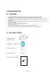
1 INTRODUCTION 1.1 FEATURES • • • • • • • • 1.
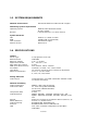
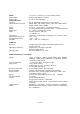
1.3 SYSTEM REQUIREMENTS Network environment LAN 10/100 Ethernet Cable CAT.5E or higher Monitoring system requirements Operating system Browser Windows 2000 Professional SP4/ XP SP2 / VISTA Internet Explorer 6.x or later versions System hardware CPU: RAM: VGA resolution: DirectX Version: Pentium 4, 2.4GHz or better 512MB (1GB recommended) 1024x768 or higher DirectX 9.0c 1.
Audio Audio modes Audio Codec Communication LAN Port Communication Protocol Alarm RS485 Status LED Power Dimensions Operating temperature Storage temperature Humidity Software Browser Application Software OS supported 1 x line in, 1 x line out, 3,5 mm stereo sockets duplex / full duplex / simplex G.711, G.
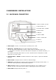
2 HARDWARE INSTALLATION 2.1 BACKPANEL CONNECTORS 1. Power 12 VDC / 24 VAC 2. Switch Video / IP 3. Terminal Alarm / RS485 4. Reset Switch 5. LAN port 6. Video out BNC 7. Power / Status LED 8. Audio in 9. Audio out 1. Power input: 12 V DC / 24 V AC input, no polarity for 12 V DC 2.
8. Audio Input: 3,5 mm audio socket for Audio line input 1 V max / 10 KOhm 9.
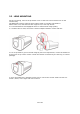
2.2 LENS MOUNTING For lens mounting, remove the protection cover at the front and screw the lens on the camera body. The EAN-1350 camera supports lenses with manual iris and DC-controlled iris. Please make sure, that the used lens supports 1/3" CCD chip format. It is recommanded to use Megapixel lenses to achieve best image quality. If a C-Mount lens is used, mount the C-Mount adapter between camera and lens.
2.3 CAMERA MOUNTING The camera monting adapter allows using standard camera brackets with 1/4" thread. The mounting adapter can be mounted at top or botton side of the camera body. 2.4 VIDEO INSTALLATION FOR CAMERA / LENS ADJUSTMENT For checking and adjusting lens and camera viewing direction connect a standard video monitor to the BNC socket. Switch the mode switch to "TV test" and switch OFF / ON camera power. In this "TV test" mode is no IP streaming possible.
2.5 ALARM IN- / OUT INSTALLATION Alarm- in- and outputs are connected to the screwless terminal at backside of the camera. For Details to input/output circuit refer to Attachment A. 2.5.1 Terminal pin assignment: Contact Description 1 2 3 4 5 6 7 8 9 10 11 Alarm IN 1 + (max 50 V DC) Alarm IN 1 Alarm IN 2 + (max 50 V DC) Alarm IN 2 Relay COM (max. 24 V DC / 1 A) Relay N.C. (max. 24 V DC / 1 A) Relay N.O. (max.
B) Installation with dry N.O. contact using external DC voltage ATTENTION: Do not exceed the maximum input voltage of 50 V DC. This may cause serious hardware damage. 2.5.3 Alarm Output The relay output provides dry contacts, maximum load is 24 V DC, 1 A. 7 (N.O.
2.6 AUDIO INSTALLATION Audio input and output are connected to the 3,5mm sockets. Please make sure to use a pre-amplified microphone with line level 1 V max. For audio output please use active speakers only. 2.7 RS-485 TELEMETRY INSTALLATION The EAN-1350 supports Pan-/Tilt/Zoom control of RS-485 PTZ receivers with Pelco-D/P telemetry protocol.
2.8 NETWORK INSTALLATION / WIRING Depending on the network environment at installation site, connect camera network connector to the LAN (switch, router, PC...). Use CAT.5 cable or better for installation. The camera network interface is auto-sensing, this means normal straight wired patch cable or crossover cable are supported.
3 IP- SETUP 3.1 NETWORK INSTALLATION / BASIC IP - SETUP WITH IP-FINDER The IP-Finder application (on application CD in camera package) is a useful tool for initial IP - setup f the camera. Start the IP-Finder at a PC, which is connected in to the same network as the camera is or use a direct network connection camera<>PC. Click on "Update" to search cameras in your network, the cameras will be listed in the left side of the screen. Mark a camera in the list by mouseclick.
3.3 NETWORK INSTALLATION / BROWSER SETUP At initial connecting by web browser an installation of the camera ActiveX control is required. Supported we browsers are Internet Explorer (version 6.0 or higher) or Mozilla Firefox (version 3.0 or higher) with installed IE-Tab Add-On. Make sure that user rights at this PC allow installation of ActiveX components. Set the security level of the browser to "Medium" for ActiveX installation. Steps: IE browser > Tools > Internet Options > Security > Custom Level 3.
Click on OK.
4 MAIN OPERATION SCREEN After successful login the main screen appears: Switch Live / setup mode Language Alarm indicator Video settings Video streaming mode Pan-Tilt control Video window size Video streaming format Alert Log Video window File path setup for record/snapshot Status display Single picture snapshot Local video record Display file path for record/snapshot 19 of 59
5 SETTINGS - BASIC SETTING 5.1 SETUP SCREEN To access the detailled camera setup click on "Settings" in upper right corner of the window. 5.2 SYSTEM The System setting page gives an overview about camera version and basic IP settings. The values are not editable at this page except the Device name.
5.2.1 System Log The administrator can view all login information of this camera, including boot record, video streaming mode, login IP, changes, and the date/time information. You can copy the entries to a Word document and save them manually. Please note that all information is deleted when you turn off the machine. Syslogd Service The Syslogd service allows to transmit log informations to a server, which provides Syslogd function.
5.3 VIDEO / IMAGE Setup menu for general video quality and streaming settings. 5.3.1 Video Sensor Scan Mode MPEG 4 Resolution 2 modes are available: Full scan: Mode with highest available resolution, reduced framerate Partial scan: In this mode 4 pixel are combined in scanning. Realtime framerate and enhanced light sensitivity are available in this mode.
Motion JPEG Resolution Full scan mode: QuadVGA 1280x960 pixel or same as MPEG4 setting, Partial scan mode: always similar to MPEG4 setting Framerate (FPS) Full scan mode: 12,5 or 8 images/second Partial scan mode: 1 ~ 12 IPS images / second Quality image quality (compression, adjustable in 5 steps) 5.3.
color palette. Select a character color by clicking in a color in the palette. Background color Color of character´s outline: clicking in the color box at right opens a color palette. Select a outline color by clicking in a color in the palette.
DayNight Setting Mode Mode for day (color) and night (b/w without IR-Cutfilter) switching: Auto: automatic switching to dayand night mode, "Status" shows the current mode (not editable) Manual: Manual setup of day / night mode External: D/N switching by external contact, setup under "EVENT" Switching delay Delay of D/N switching in AUTO - mode. Setup range 1~15 seconds. A longer delay time avoids false D/N switching caused by car light, clouds, reflections or other effects.
5.4 AUDIO The EAN-1350 provides bidirectional audio transmission with different quality options. Mode Audio In Codec Gain Audio out Codec Gain Full duplex: Allows using a microphone and amplifier at the same time, or turning them off at main page. Half duplex: Allows using a microphone or amplifier by manual switch. Simplex microphone only: Allows using the microphone only. Simplex amplifier only: Allows using the speaker only. Audio off: Turns audio off; i.e.
5.5 PTZ This Setup page contains settings for electronic zoom and external RS-485 PTZ devices. The EAN-1350 provides control of 2 PTZ devices, this allows a combined control of electronic zoom and external PTZ - device.
PTZ Driver Upload Upload of new available PTZ drivers: Search: Enter the file path to the new PTZ driver files.
Add / Modify / Delete User Press "Add" to define a new user, "Update" to modify the settings for a selected user. "Delete" removes a user from the list ("user1" can not be deleted). User setting: anonymous login "Enable" allows access to the camera without login by username /password. This function could be helpful for public cameras, for security applications the default setting "Disable" is recommended.
The EAN 1350 provides 4 level of different user rights.
5.7 NETWORK 5.7.
EAN-1350 Installation / Operation 5.7.2 Services The FTP function allows FTP access to the camera. This function is currently not supported by this camera model. 5.7.3 Streaming Streaming method Setting HTTP Port 80(80 by default) can pass through most firewalls under Internet environment. Video streams are transmitted through HTTP Port (80 by default) to ensure passage through firewalls. RTSP Port 554 uses a fixed port (i.e. TCP) or can be defined by users to ensure reliable data transmission.
EAN-1350 Installation / Operation 5.7.4 PPPoE PPPoE ( Point-to-Point Protocol over Ethernet) is a protocol that supports access to a high-speed wideband network using a PC and a wideband modem (such as xDSL, Cable, Wireless modem). The user need only to equip the PC with an Ethernet card and apply to an ISP and an ADSL provider for ADSL service to roam the Internet through ordinary twisted copper wires. PPPoE is applicable to networking via a xDSL or cable modem.
EAN-1350 Installation / Operation 5.7.5 DDNS DDNS (Dynamic Domain Name Service) provides a central (public) database where DNS information can be stored and retrieved. It allows those using a dynamic IP address (i.e. one where it changes each time the computer connects to the internet) to be registered centrally so others can connect to it by name.
EAN-1350 Installation / Operation 5.7.6 UPnP UPnP (Universal Plug and Play) If you connect your camera to a router, IP allocator, or wireless AP, the camera will possibly be blocked by the NAT (network address translation) and can’t be located on the Internet. To penetrate the firewall, activate the supportive item UPnP. The Link URL shows the external IP address and the port of the router.
EAN-1350 Installation / Operation To activate the UPnP function in Windows OS: Ex: Windows XP: Windows component installation. 1. 2. 3. 4. 5. 6. Click Control Panel Click Add/Remove Programs Click Add/Remove Windows Components Click Networking Services Click Detail Check / add UPnP User Interface Firewall settings 1. 2. 2. 3. Click Windows Firewall in the Control Panel Open Windows firewall option Click Exceptions Check UPnP configuration and edit ports, if needed.
EAN-1350 Installation / Operation 5.7.
EAN-1350 Installation / Operation 5.7.8 SAMBA The EAN-1350 supports SAMBA server for storage of event snapshots and video recordings.
EAN-1350 Installation / Operation 5.7.9 Notification Notification service for installations with dynamic IP-Adressing. After IP-Adress change the camera can send out notification by email, ftp or HTTP. This service is not needed for installations with fixed IP-Address.
EAN-1350 Installation / Operation 5.7.10 Multicast This function allows multiple people to watch video streaming without limitation on the number of users. Multicast is only applicable in the LAN environment. The function requires support of Multicast function in the connected network. The video streaming format (MPEG4/MJPEG) depends on the selected image format setting in Video settings.
EAN-1350 Installation / Operation 5.7.11 Date / Time The EAN-1350 camera supports date / time setting in manually, synchronized with client PC or automatic adjustment by NTP time server. Date / Time Setting Server Time Current time and date of the camera, display only.
EAN-1350 Installation / Operation Switch from Time for switching to DST and updated time End time End date of DST Switch from Time for switching off DST and updated time 5.7.12 IP Filtering The EAN-1350 provides IP filtering for network access to the camera based on a blacklist or whitelist.
EAN-1350 Installation / Operation 6 SETTINGS - APPLICATION SETTING 6.1 EVENT 6.1.1 Event These setup pages provide settings for event related actions such as recording, notification and contact output. Add / Modify Event Press "Add" to define a new event. Depending on current settings several status / warning messages for event related settings may appear.
EAN-1350 Installation / Operation Event Setting Name Name of the event (appears in the event list) Response to event trigger Always: permanent event handling During time: simple weekly schedule function for event handling, set a start time and a duration of activity (in hours, max 168) Example: Event handling shall be activated from Saturday 08:00 am to Monday 8:00 am.
EAN-1350 Installation / Operation SERVER menu is required to activate server upload. Send TCP notification In case of event the camera will send a notification message to a TCP server. Note: A definition of Notification server in EVENT > EVENT SERVER menu is required to activate server upload. Send NAP notification In case of event the camera will send a notification message and alarm image to a NAP server. Use this function to create network alarm event for PowerCon management software (Version 4.
EAN-1350 Installation / Operation 6.1.2 Trigger This menu provides setting for alarm input contact modes and test functions. Event Setting Alarm Input 1 / 2 Contact mode of alarm inputs, Normal Open or Normal Closed. Triiger Alarm Out Manual trigger of relay output (latched function). "Clear" releases the relay. Trigger Mail Test of email transmission. Trigger FTP Test FTP: a test video file will be transmitted to FTP.
EAN-1350 Installation / Operation 6.1.3 Event Server Setup for the event servers. Press "Add FTP", "Add HTTP", "Add TCP" or "Add UDP" to define the access data for event servers. Press "Modify" to change selected server. Press "Remove" to delete event server.
EAN-1350 Installation / Operation 6.2 MOTION DETECTION The EAN-1350 offers motion detection in 3 independent zones. Zone 3 can be defined as "Exclusive" zone, no motion will be detected. Setup of "EXCLUSIVE" zone: Motion detection Setting Area 1 ~ 3 Set the checkbox to enable the motion detection zone. Click on "AREA1(2,3)" to show the detection area. Click in der middle of the zone to move the area, click at the borders to change area size.
EAN-1350 Installation / Operation 6.3 FIRMWARE UPGRADE Firmware upgrade Setting Model Shows the camera type Hardware version Shows hardware version of the camera Firmware version Shows current firmware version Firmware build time Creation date of current firmware Firmware upgrade Search Submit Enter the file path to the upgrade firmware file Send the selected firmware file to the camera. This procedure may take several minutes. follow the screen instructions.
EAN-1350 Installation / Operation 6.4 FACTORY DEFAULT This menu allows to load factory default values and backup / restore camera settings. Factory Default Setting Resets all settings, except IP - parameters All values will be set to factory defaults except the basic settings for IP parameters. Resets all parameters All parameters incl. IP settings are set to factory default values. Backup all parameters Saves the current camera settings in a configuration file. Confirm to save the file.
EAN-1350 Installation / Operation 6.5 REBOOT Press "Reboot" to initialize the camera by restarting. A confirmation popup will appear. Confirm the request with "OK".
EAN-1350 Installation / Operation 7 OPERATION 7.1 MAIN SCREEN CONTROLS After successful login the main screen appears: Switch Live / setup mode Language Alarm indicator Video settings Video streaming mode Pan-Tilt control Video window size Video streaming format Alert Log Video window File path setup for record/snapshot Status display Single picture snapshot Local video record Display file path for record/snapshot 7.
EAN-1350 Installation / Operation Transmission mode of the video stream, the ideal mode depends on the network conditions: UDP: Provides the fastest but most unreliable transmission service. Video steams are transmitted through UDP Port (50000~60000 by default) to ensure the fastest image transmission. However, video fragment or mosaics may occur due to poor transmission quality. TCP: Provides reliable data transmission.
EAN-1350 Installation / Operation 7.4 PAN / TILT / ZOOM Depending on setting the PTZ control works with electronic zoom (setting EZOOM in > SETTING > PTZ) or with external PTZ devices. PTZ-Device: Select a PTZ device (setup in > SETTING > PTZ) Zoom IN / OUT: Zoom In or Out in the picture. Arrow keys: Move a zoomed picture up/down/left/right Speed: Speed of pan / tilt movements NOTE: This way of PTZ operation is global for this video stream.
EAN-1350 Installation / Operation 7.5 RECORD / SNAPSHOT SETTING Click on to define the settings for manual record and snapshots. Recording Path Doubleclick in the setup field to define the folder location for manual records. Filename Prefix Define a prefix for the record file name. The file name contains the prefix, start date and start time. Example: Prefix: Start Date: Start Time: Record File Size / Record Duration Lobby1_20090128-142524.avi Lobby1 Jan. 28.
EAN-1350 Installation / Operation 7.6 MANUAL RECORD Press on "REC" to start a manual record. The file format is AVI. The storage location is defined by the "PATH" icon. The icon will start to flash. A RECORD symbol appears in lower left corner of the video window. Press "REC" again to stop the record. The record will also stop after reaching maximum file size / maximum recording duration, which is defined in "PATH". Note: Record will also stop with closing the Browser! 7.
EAN-1350 Installation / Operation 7.8 AUDIO The audio fuctionality depends on the installation and on settings in > SETTINGS > AUDIO. Listen Audio transmission from camera to client PC. Click on the icon to switch the mode. No audio from camera to client PC. Click on the icon to switch the mode. Speak Audio transmission from client PC to camera. Click on the icon to switch the mode. No audio transmission from client PC to camera. Click on the icon to switch the mode. 7.
EAN-1350 Installation / Operation 8 ATTACHMENT A: ALARM INTERFACE CIRCUIT 58 of 59
EAN-1350 Installation / Operation EverFocus Electronics Corp. Head Office: 12F, No.79 Sec. 1 Shin-Tai Wu Road, Hsi-Chih, Taipei, Taiwan www.everfocus.com.tw China Subsidiary: Room 609, Technology Trade Building, Shandgdi Information Industry Base, Haidian District, Beijing,China www.everfocus.com.cn USA Subsidiary: 1801 Highland Ave. Unit A Duarte, CA 91010, U.S.A. www.everfocus.com Japan Subsidiary: 1809 WBG MARIBU East 18F, 2-6 Nakase.Mihama-ku. Chiba city 261-7118, Japan www.everfocus.