EVERFOCUS 560 TVL True Day/Night Indoor Vandal Color Camera Operation Instructions Model No. ED550 Please read this manual first for correct installation and operation. This manual should be retained for future reference. The information in this manual was current when published. The manufacturer reserves the right to revise and improve its products. All specifications are therefore subject to change without notice. PRECAUTIONS 1. Do not install the camera near electric or magnetic fields.
TABLE OF CONTENTS 1. PRODUCT OVERVIEW ...................................................................................................... 4 1.1 Main Features ............................................................................................................................................. 4 1.2 Package Contents ....................................................................................................................................... 4 1.3 Specifications .............................
5.8.7 SHARPNESS ........................................................................................................................................ 24 5.8.8 RESET................................................................................................................................................... 24 5.8.9 RETURN ............................................................................................................................................... 25 5.9 Exit .........................
1. PRODUCT OVERVIEW The new ED550 camera is designed with advanced new generation 16-bit DSP which has powerful processing capability to show over 560TVL horizontal resolution. Built-in DNR (Dynamic Noise Reduction) function, the camera performs clear & crisper image in low light and substantial disk-saving effect. In addition, designed with SENS-UP slow shutter technology, the starlight super-high sensitivity of 0.002 Lux is achieved.
1.3 Specifications Pickup Device Video Format Scanning System Picture Elements Horizontal Resolution Sensitivity S/N Ratio Electronic Shutter Lens Type True Day/Night: Back Light Comp. Auto Gain Control DNR Auto White Balance Gamma Correction Flickerless Video Output Sync.
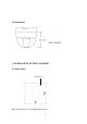
1.4 Dimensions 2. NAMES AND FUNCTIONS OF PARTS 2.1 Front Panel Internal Sensor Note: Internal Sensor is a Day/Night Switch Sensor.
-7-
2.2 Back Panel (6) (5) (1) (2) (3) (4) (7) (1) Power Input Terminal & Video Output Connector Connect to the appropriate power to each model. Video Output connector is for connecting the video output of the camera to a color monitor or other video devices through a 75 Ohm type coaxial cable with BNC female connector at backside of the camera.
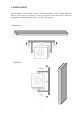
3. INSTALLATION Take off camera's cover first. Fix 3 screws of the bracket firmly to wall or ceiling. Adjust the camera to best angle for viewing. Use the tact switcher at the back panel to make any adjustment if needed. Finally, place the cover back to the camera.
4. CAMERA SETUP OPERATIONS This camera utilizes an On Screen Display (OSD) user setup menu. 4.1 Setup Button To set items on the user setup menu, use the following switch on the back panel. z Up: Adjust the switch to move the cursor upwards. This is used to select the item need to be set. z Down: Adjust the switch to move the cursor downwards. This is used to select the item need to be set. z Right: Adjust the switch to right direction.
4.2 Display/Close the user setup menu screen SETUP > LENS SHUTTER WHITE BAL. BACKLIGHT AGC DNR SENS-UP SPECIAL <┘ EXIT Set button DC <┘ ___ ATW OFF MIDDLE LOW AUTO <┘ I. Press the SET button The menu screen will appear on the monitor as the block shown above. II. Using the cursor switch Adjust the switch c or d to move the cursor up or down. Move the switch e or f to adjust the mode or parameter of settings. III.
5. USER SETUP 5.1 Lens 1. When the SETUP menu is displayed on the screen, please direct the arrow to point to “LENS” by adjusting the switch to UP or DOWN direction. SETUP > LENS SHUTTER WHITE BAL. BACKLIGHT AGC DNR SENS-UP SPECIAL <┘ EXIT LENS DC <┘ ___ ATW OFF MIDDLE LOW AUTO <┘ LEVEL |+++++++++| 20 NOTE: 1.ED550 does not support Manual lens, please do not select lens to Manual mode, as it may cause malfunction of lens. 2. The brightness of the screen can be adjusted on DC mode in LENS LEVEL.
SETUP LENS > SHUTTER WHITE BAL. BACKLIGHT AGC DNR SENS-UP SPECIAL <┘ EXIT MANUAL FLK ATW OFF MIDDLE LOW ___ Ö ESC: The shutter speed can automatically be controlled. When ESC mode turns on, the auto control of the shutter speed can be performed according to the brightness of the screen. The range of ESC is 1 ~ 70. SETUP LENS > SHUTTER WHITE BAL.
5.3 White Balance Control The screen color can be adjusted by using the WHITE BALANCE function. 1. Please direct the arrow to point to “WHITE BAL” on the SETUP menu by adjusting the switch to UP or DOWN direction. 2. Please select the mode you would like to operate by adjusting the switch to LEFT or RIGHT direction.
5.4 Backlight Even there is a massive backlight behind the object, bright images of the background and the object can still be obtained by using the BACKLIGHT function. 1. Please direct the arrow to point to “BACKLIGHT” on the SETUP menu by adjusting the switch to UP or DOWN direction. 2. Select the mode you would like to operate by adjusting the switch to LEFT or RIGHT direction. SETUP LENS SHUTTER WHITE BAL.
5.6 DNR (Dynamic Noise Reduction) Dynamic Noise Reduction in video images has the following effects. 1. Images are brighter and sharper. 2. When the level of noise is reduced, the performance of a camera can apparently be improved. 3. When it is recorded digitally, reduced noise can reduce image file size. As the level of gain changes, the background noise in the low light level automatically decreases. 1.
SETUP LENS SHUTTER WHITE BAL. BACKLIGHT AGC DNR > SENS-UP SPECIAL <┘ EXIT LIMIT DC <┘ ___ ATW OFF MIDDLE LOW AUTO <┘ > AUTO X 10 Ö OFF: The function is disabled. NOTE: 1. When SHUTTER is in the manual mode, SENS UP will be disabled. 2. When AGC is turned off, SENS-UP will be disabled. 2. Press SET button when you finish all the settings. NOTE: 1. The maximum storage magnification in low light level movement situations can be adjusted by pressing the SETUP button in “AUTO” mode. 2.
SPECIAL > CAMERA ID COLOR ADJ. <┘ SYNC. MOTIION DET PRIVACY MIRROR SHARPNESS RESET RETURN <┘ OFF INT OFF OFF OFF ON <┘ 5.8.1 CAMERA ID Input the camera ID, and it will be appeared on the monitor. 1) Please direct the arrow to point to “CAMERA” by adjusting the switch to UP or DOWN direction. 2) Select “ON” by adjusting the switch to LEFT or RIGHT direction. 3) Press SET button. 4) Maximum 15 letters can be used for the ID.
5.8.2 COLOR ADJ Adjust the Color Gain from 0 ~ 15 SPECIAL CAMERA ID > COLOR ADJ. <┘ SYNC. MOTIION DET PRIVACY MIRROR SHARPNESS RESET RETURN <┘ OFF COLOR GAIN. INT OFF OFF OFF ON <┘ > LEVEL |++++++++| 8 5.8.3 SYNC There are two SYNCHRONIZATION modes: INTERNAL and EXTERNAL LINE-LOCK. In LINE-LOCK mode, without a synchronous generator, it synchronizes the video signal between cameras. The Line-Lock synchronization is only used in the places of 60Hz (NTSC models) or 50Hz (PAL models).
SPECIAL MOTION DETECTION CAMERA ID COLOR ADJ. <┘ SYNC. > MOTIION DET PRIVACY MIRROR SHARPNESS RESET RETURN <┘ OFF > AEREA SEL AREA STATE TOP INT ON <┘ OFF OFF ON <┘ DOWN LEFT RIGHT AREA1 ON |+++++++++| 10 |+++++++++| 25 |+++++++++| 20 |+++++++++| 40 z Please select the area you would like to detect from the 4 areas in AREA SEL mode. z Please select ON mode for the chosen area.
2. Increase DOWN scale value by 20. AREA1 position after change is: TOP: 10, DOWN: 45, LEFT: 20 and RIGHT: 40. AREA1 3. Increase TOP scale value by 20. AREA1 position after change is: TOP: 30, DOWN: 45, LEFT: 20 and RIGHT: 40. AREA1 4. Increase RIGHT scale value by 20. AREA1 position after change is: TOP: 30, DOWN: 45, LEFT: 20 and RIGHT: 60. AREA1 5. Increase LEFT scale value by 20. AREA1 position after change is: TOP: 30, DOWN: 45, LEFT: 40 and RIGHT: 60.
5.8.5 PRIVACY This mode covers the areas you do not want to see on the screen. 1) Please direct the arrow to point to “PRIVACY” by adjusting the switch to UP or DOWN direction. 2) Select “ON” by adjusting the switch to LEFT or RIGHT direction. 3) Press SET button. SPECIAL CAMERA ID COLOR ADJ. <┘ SYNC. MOTIION DET > PRIVACY MIRROR SHARPNESS RESET RETURN <┘ PRIVACY OFF > AEREA SEL AREA STATE.
1. The original position of AREA1 was TOP: 10, DOWN: 25, LEFT: 20 and RIGHT: 40. AREA1 2. Increase DOWN scale value by 20. AREA1 position after change is: TOP: 10, DOWN: 45, LEFT: 20 and RIGHT: 40. AREA1 3. Increase TOP scale value by 20. AREA1 position after change is: TOP: 30, DOWN: 45, LEFT: 20 and RIGHT: 40. AREA1 4. Increase RIGHT scale value by 20. AREA1 position after change is: TOP: 30, DOWN: 45, LEFT: 20 and RIGHT: 60. AREA1 5. Increase LEFT scale value by 20.
z In order to save the changes and complete the setting, press the SET button. This allows you to return to the previous menu. 5.8.6 MIRROR -ON: Sets a horizontal image inversion. -OFF: Disable the inversion. SPECIAL CAMERA ID COLOR ADJ. <┘ SYNC. MOTIION DET PRIVACY > MIRROR SHARPNESS RESET RETURN <┘ OFF INT OFF OFF OFF ON <┘ 5.8.7 SHARPNESS The contour of the video image becomes cleaner and more distinguishing as the level of SHARPNESS increases.
5.8.9 RETURN It saves all settings in SPECIAL menu and returns to the SETUP menu. SPECIAL CAMERA ID COLOR ADJ. <┘ SYNC. MOTIION DET PRIVACY MIRROR SHARPNESS RESET > RETURN <┘ OFF INT OFF OFF OFF ON <┘ 5.9 Exit Save all the setting menus and exit. NOTE: If you quit the Menu without pressing EXIT, all the settings you previously did will NOT be saved.
EverFocus Electronics Corp. Head Office: 12F, No.79 Sec. 1 Shin-Tai Wu Road, Hsi-Chih, Taipei, Taiwan TEL: +886-2-26982334 FAX: +886-2-26982380 www.everfocus.com.tw USA L.A. Office: 1801 Highland Ave. Unit A Duarte, CA 91010, U.S.A. TEL: +1-626-844-8888 FAX: +1-626-844-8838 www.everfocus.com USA N.Y. Office: 415 Oser Avenue Unit S Hauppauge, NY 11788 TEL: 631-436-5070 FAX: 631-436-5027 www.everfocus.