Administrator’s Guide and Operating Instructions Administrator’ s Guide and Operating Instructions Digital Video Recorder EDR1600 Version 3.
Administrator’s Guide and Operating Instructions WARNING TO REDUCE RISK OF FIRE OR ELECTRIC SHOCK, DO NOT EXPOSE THIS APPLIANCE TO RAIN OR MOISTURE. CAUTION DO NOT REMOVE COVER. NO USER SERVICEABLE PARTS INSIDE. REFER SERVICING TO QUALIFIED SERVICE PERSONNEL. WARNING: This equipment has been tested and found to comply with the limits for a Class “A” digital device, pursuant to part 15 of the FCC Rules.
Administrator’s Guide and Operating Instructions PRECAUTIONS ?? Refer all work related to the installation of this product to qualified service personnel or system installers. ?? Do not block the ventilation opening or slots on the cover. ?? Do not drop metallic parts through slots. This could permanently damage the appliance. Turn the power off immediately and contact qualified service personnel for service. ?? Do not attempt to disassemble the appliance.
Administrator’s Guide and Operating Instructions Table of Contents 1. Product Overview… … … … … … … .… … … … … … … … … .… … ... 1.1 Features… … … … … … … ..… … … .… … … … ..… … … … … … … ... 1.2 Technical Overview… … .… .… … .… … … … … … … … … … .… … .. 2. Front & Rear Panels… .… … .… … … … … … … … … … … … .… … . 3. System Installation… … .… … .… … … … … … … … … … … … .… … 3.1 Before Installation… … .… … … .… … … … … … … … … … … .… … . 3.2 Basic Connections… … … … … .… … … … … … … … … … … .… … .. 3.
Administrator’s Guide and Operating Instructions 1. Product Overview The PowerPlex EDR1600 is a state-of-the-art digital video recorder that brings unparalleled price/performance video surveillance, recording and playback to the CCTV systems. With parallel processing architecture, high performance video engine, and intelligent recording algorithms, triplex operation can be easily achieved without sacrificing the increasing demands of performance, reliability, and availability in the CCTV industry. 1.
Administrator’s Guide and Operating Instructions 1.2 Technical Overview 1.2.1 Video Input and Output The digital video recorder is designed to support either NTSC/EIA or PAL/CCIR standard. To make the auto detection of video standard work, at least one camera must be connected to the video input. The product features video camera inputs with a passive looping output for each. Camera input impedance termination is set independently for each camera automatically.
Administrator’s Guide and Operating Instructions During video playback, the selected pictures can be saved to floppy disk, ZIP disk, CD-RW, DVD RAM etc. in .MPG format for MPEG-1 encoded video or .MOV format for JPEG encoded video. For Time-Lapse Mode Recording Time, please refer to Appendix B. 1.2.4 Motion Detection The digital video recorder continuously monitors all camera inputs for motion.
Administrator’s Guide and Operating Instructions 1.2.7 Expandable IDE Hard Disk Architecture All the other HDD-based digital video recorders support only 1-4 hard disks. If those recorders do support more hard disks, they usually use RAID (Redundant Arrays of Independent Disks) or SCSI disks, which are very expensive. With the Expandable IDE Hard Disk Architecture, the EDR1600 can support up to 18 pieces of IDE hard disks that are hot swappable.
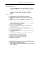
Administrator’s Guide and Operating Instructions 2. Front & Rear Panels The following is a brief overview of the front panel and rear panel of EDR1600. Rear Panel 19 1 2 20 3 4 21 5 6 22 23 8 7 24 9 10 25 11 12 13 14 18 15 16 17 1. Power Switch From Rear Panel 2. Power Selector Switch: 115V AC or 230V AC selector switch. Warning: To avoid damaging the system, set this switch before plugging in the power plug.
Administrator’s Guide and Operating Instructions 6. 2 USB Connectors: Connect to USB port devices, e.g. CD-RW, DVD RAM, printer, ZIP. 7. RS-232 Connector: Com 1, connects to modem. 8. Printer Port Connector: Connects to printer port devices (e.g. ZIP/printer port). 9. RS-232 Connector: Com 2, connects to PTZ camera. 10. Audio Out: Connect to speakers or other audio out devices. 11. Audio In: Connect to microphone or other audio in devices. 12. VGA Monitor Output. 13.
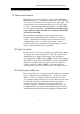
Administrator’s Guide and Operating Instructions Front Panel 29 28 27 26 26. Hard Disk Trays: Hard disk holders for HDD#1 (upper tray) and HDD#2 (lower tray). (Note1.2) Please make sure to set HDD#1 as master and HDD#2 as slave. The settings should be described on the hard disk itself or in the manual come with the hard disk. 27. Floppy Drive: 3.5”, 1.44MB. 28.
Administrator’s Guide and Operating Instructions 3. System Installation The installations described below should be made by qualified service personnel or system installers. 3.1 Before Installation Please make sure to set the Power Selector Switch before plugging in the power plug to avoid damaging the EDR1600. Use a screwdriver to set the switch to the correct position so that the number shown is the same as the local AC voltage. Please refer to the following diagram for the system connections.
Administrator’s Guide and Operating Instructions 3.2 Basic Connections ?? Cameras Connect each of the camera video input connector to the video output from a camera or other composite video source. At least one camera must be connected before the system is running for the auto detection of video standard to take effect. ?? VGA Monitor Connect the VGA monitor output connector to a VGA monitor. The VGA monitor displays selected live or recorded cameras in any available format.
Administrator’s Guide and Operating Instructions ??EDA800 Connect the External Hard Disk Connector to EDA800 if the user has purchased EDA800. If EDR1600 is running, please power on EDA800 first, and then make the connection. ??PTZ Camera Connect the PTZ camera to the RS-232(Com #2) connector at system start up. The system supports 4 models of PTZ camera: EverFocus ED2200, Pelco D protocol Dome, SamSung SCC-641P and Kalatel Cyber Dome.
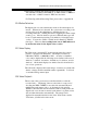
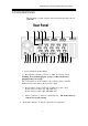
Administrator’s Guide and Operating Instructions 4. Main Screen Camera 1 Live Camera 2 Live Camera 3 Live Camera 4 Live 36% The diagram above is the main screen display. The icons on the lower corner of the screen are mainly for control and configuration, those on the right corner for status indication. If any icon is grayed, it means that the specific function is not accessible in the current mode or login right. The followings are a brief description for each of the icons.
Administrator’s Guide and Operating Instructions TV Overscan/Underscan – To change the display size of the Main TV Monitor. Login – To login the system as Administrator, Supervisor or Operator. Sequence Mode / Static Page Mode – To toggle between Sequence Mode and Static Page Mode. In Sequence Mode, each page in the designated sequence will be shown for its preset dwelling time sequentially. To select the Sequence, click on the Up/Down buttons beside the displayed sequence number.
Administrator’s Guide and Operating Instructions order is Camera, Alarm Output, Hard Disk, Alarm Input, then back to Camera. Each status bar stands for the status of one device, the bottommost for ID#1. There are 5 different colors: GRAY/BLACK – Not existent or not installed, GREEN – Normal, YELLOW – Video Loss detected for Camera, Alarm for Alarm Input/Output, and Recording for Hard Disk RED – Motion detected for Camera. 4.
Administrator’s Guide and Operating Instructions 5. Basic Operations & Log Display If the user does not login the system, he will be treated as a guest and can only view the live video display and device status. To login as an Operator or Supervisor, please click on the Login icon, and enter the appropriate Operator’s Login name and Password (For Operator, the factory default value for both of them is operator, for Supervisor, the factory default value for both of them is supervisor).
Administrator’s Guide and Operating Instructions There are 6 kinds of event logs: User Login (Local/Remote), Alarm, Motion, Video Loss, Hard Disks Full and Power On/Off. To view the event Log display, please click on the Log icon. The screen will be shown as below: If you logged in as Administrator, the Delete button and Delete All button will be enabled. Click on the Delete button to delete the highlighted event log, and click on the Delete All button to delete all the event logs. 5.
Administrator’s Guide and Operating Instructions 6. Setup (Administrator) To login as an Administrator, please click on the Login icon, and enter the appropriate Administrator’s Login name and Password (the factory default value for both of them is admin). To setup the behaviors of the system, please click on the Config icon. The configuration menu will pop up as below. Click on the menu item for the respective configuration. For the details of each item, please refer to the following paragraphs.
Administrator’s Guide and Operating Instructions 6.1 Time Type Setup The behavior for the system is the same when it’s in the same time Type (or Time Mode). Please refer to Camera Setup and Motion Setup for how they depend on Time Type. There are 2 default Time Types, On duty and Off duty, in the system. However, you may configure up to 16 Time Types to suit your needs. Use the meaningful names no matter they are from human viewpoint or the system’s viewpoint.
Administrator’s Guide and Operating Instructions 6.2 Day Type Setup The daily behaviors for the system are the same for those days configured as of the same Day Type. There are 2 default Day Types, WORK DAY (Monday through Friday) and HOLIDAY (Saturday and Sunday), in the system. However, you may configure up to 16 Day Types to suit your needs. For each Day Type, you may configure up to 16 time segments and their corresponding Time Types, beginning time and end time.
Administrator’s Guide and Operating Instructions 6.3 Calendar Setup The Calendar setup is provided for the administrator to set the Day Type of each calendar day. It’s designed to be a Perpetual Calendar. However, up to 10 years of calendar days can be configured at any specific time. Operations: After the Calendar menu item is selected, the Calendar Setup dialog box will be shown on the screen.
Administrator’s Guide and Operating Instructions 6.4 Alarm Action Setup The Alarm Actions allow the administrator to define how the digital video recorder responds to the triggered alarm from the Alarm Inputs. There are up to 16 Alarm Actions that correspond to 16 (Focus) Cameras for most applications. For each Alarm Action, you may configure its behaviors as shown on the screen and described below.
Administrator’s Guide and Operating Instructions ??Go to Preset- The option will be available while the focus camera is a PTZ camera. Check the box and enter the desired preset location. The corresponding PTZ camera will automatically go to the preset location while the alarm action is triggered. For more details of the preset location settings, please refer to Chapter 7 PTZ Control Functions.
Administrator’s Guide and Operating Instructions ?? Record Audio – To enable audio recording function while the alarm action is triggered. ?? Call Display – If it is checked, the Call Monitor will switch to the Focus Camera when the Alarm Action is triggered. Otherwise, the Call Monitor will switch among the cameras according to setting. Please refer to 6.15 Set Call Monitor for the setup details. ?? Send Mail - To activate the e-mail notification function or not when the Alarm Action is triggered.
Administrator’s Guide and Operating Instructions 6.5 Motion Action Setup The Motion Actions allow the administrator to define how the digital video recorder responds to the detected motion for the cameras. There are up to 8 Motion Actions that correspond to 8 Alarm Outputs for most applications. The Focus Camera is always the camera with the detected motion. For each Motion Action, you may configure its behaviors as shown on the screen and described below.
Administrator’s Guide and Operating Instructions 6.6 Video Loss Action Setup The Video Loss Actions allow the administrator to define how the digital video recorder responds to the detected video loss for the cameras. There are up to 8 Video Loss Actions that correspond to 8 Alarm Outputs for most applications. The Focus Camera is always the camera with the detected video Loss. For each Video Loss Action, you may configure its behaviors as shown on the screen and described below.
Administrator’s Guide and Operating Instructions 6.7 Hard Disks Full Action Setup The Hard Disks Full Actions allow the administrator to define how the digital video recorder responds when the hard disk drives reach the maximum storage capacity. Operations: After the HDDs Full Action menu item is selected, the HDDs Full Action Setup dialog box will be shown on the screen.
Administrator’s Guide and Operating Instructions ?? Output – Alarm Out output state when the hard disk capacity is full. For NC signal, it’s always open, for NO signal close. The Normal State above shows whether the selected Alarm Out is NC signal or NO signal. ?? Buzzer On – To activate the internal buzzer or not when the full hard disk capacity is detected. ?? Log – Log to event log list or not. Please refer to Log Display for the details.
Administrator’s Guide and Operating Instructions 6.8 Camera Setup The Camera Setup allows the administrator to define the behaviors for each Camera at each Time Type. There are up to 16 Cameras connected to the system. For each Camera and each Time Type, you may configure the behaviors as shown on the screen and described below. Operations: After the Camera menu item is selected, the Camera Setup dialog box will be shown on the screen.
Administrator’s Guide and Operating Instructions ?? Tag Color – To select the text color of the corresponding camera tag name. Use the Up/Down arrow buttons to select, the color will be shown on the screen above. ?? Installed – Check this item if the selected Camera is installed. If the selected Camera is installed, all the items in the Behaviors For Each Camera are settable. The default setting is installed.
Administrator’s Guide and Operating Instructions ??Video Loss Action – The corresponding Video Loss Action (always enabled). ??Normal Record (FPS) – The normal recording rate for the selected Camera at the selected Time Type. Use the Up/Down arrow buttons to adjust the value (0-30). The default value is 0.1 Frame Per Second (or 6 Frame Per Minute). (Note) ??Alarm Record (FPS) – The alarm-recording rate for the selected Camera at the selected Time Type.
Administrator’s Guide and Operating Instructions 6.9 Alarm In Setup The Alarm In Setup allows the administrator to define the behaviors for each Alarm Input at each Time Type. There are up to 24 Alarm Inputs connected to the system. For each Alarm Input and each Time Type, you may enable/disable and select its corresponding Alarm Action. For most applications, 16 Alarm Inputs are enough to correspond to 16 Alarm Actions and hence 16 (Focus) Cameras. 8 more Alarm Inputs are reserved for users’convenience.
Administrator’s Guide and Operating Instructions ?? Normal State – NC or NO, please check the signal types connected to the Alarm Input Terminal on the rear panel of the system. Use the Down arrow button to select the signal type. ?? Enable Alarm Action – Check to Enable Alarm Action for the selected Alarm Input at the selected Time Type. ?? Alarm Action – The corresponding Alarm Action if the Alarm Input changes its state from normal to alarm. Up to 16 Alarm Actions are selectable.
Administrator’s Guide and Operating Instructions 6.10 Alarm Out Setup The Alarm Out Setup allows the administrator to define the tag name for each Alarm Output. There are up to 4 Normally Closed (NC) signals (AO 1-4) and 4 Normally Open (NO) signals (AO 5-8) for the system. Operations: After the Alarm Out menu item is selected, the Alarm Out Setup dialog box will be shown on the screen.
Administrator’s Guide and Operating Instructions 6.11 Display Sequence Setup The Display Sequence Setup allows the administrator to define the Sequence Mode display. Please refer to Chapter 4 for Sequence Mode display. For the definition of the Display Pages in each Display Sequence, please refer to Display Page Setup. Operations: After the Display Seqs menu item is selected, the Display Sequence Setup dialog box will be shown on the screen. The following is a brief description for each item shown above.
Administrator’s Guide and Operating Instructions 6.12 Display Page Setup The Display Page Setup allows the administrator to define the Display Pages in Sequence Mode display and Static Page Mode display (please refer to Chapter 4). Operations: After the Display Pages menu item is selected, the Display Page Setup dialog box will be shown on the screen. 1 ? 1 5 Camera 01 Please select Sequence Mode or Static Page Mode first.
Administrator’s Guide and Operating Instructions ?? Static Page Mode – To set the Display Pages for Static Page Mode display. ?? Sequence No – To select the Sequence Number in Sequence Mode display. Use the Down arrow button to select the number. ?? Page No - To select the Page Number for the selected Sequence Number in Sequence Mode display. Use the Down arrow button to select the number. ?? Page Dwell Time – The Dwell Time (in seconds) for the selected Page shown in Page No.
Administrator’s Guide and Operating Instructions 6.13 Motion Setup The Motion Setup allows the administrator to configure how motion detection works for each Camera at each Time Type. For each Camera and each Time Type, you may configure the Detection Area (16x12 grids) and Sensitivity as shown on the screen and described below. Operations: After the Motion menu item is selected, the Motion Setup dialog box will be shown on the screen. Please select the Camera and the Time Type first.
Administrator’s Guide and Operating Instructions ?? Camera – Use the Down arrow button to select the camera. ?? Time Type - Use the Down arrow button to select the Time Type. ?? Set – To set the Detection Area – active at down position. Clear – To clear the Detection Area – active at down position. ?? Video Window – Showing the images for the selected Camera. Dragging the mouse inside to set (clear) the Detection Area. The motion detection is enabled for the area with net on it.
Administrator’s Guide and Operating Instructions 6.14 Password Setup The Password Setup allows the administrator to set the new Login names and Passwords for the Administrator, Supervisor and Operator. The system allows up to 5 user accounts for each login level. The default (Login, Password) for the Administrator is (admin, admin), the Supervisor (Supervisor, Supervisor), the Operator (operator, operator).
Administrator’s Guide and Operating Instructions 6.15 System Configurations The System Configurations Setup allows the administrator to set up the communication, main monitor sharpness-adjusting, daylight saving time, TV system and backup the configurations to floppy diskette or restore the configurations from the backup floppy diskette. Operations: After the System menu item is selected, the System Configurations dialog box will be shown on the screen.
Administrator’s Guide and Operating Instructions ?? Domain Name Server IP Address – Enter the correct Domain Name Server for mapping Domain Names to IP addresses. The default setting is 168.095.001.001. The user can also defines their local Domain Name Sever for name-to address translation, however, please make sure to define a correct - Dial Up Configurations After the Dial up item is selected, the Dial up Configurations dialog box will be shown on the screen.
Administrator’s Guide and Operating Instructions ?? ? ??? ? Dialin detail – If ISDN is selected as the dialup method, please define EAZ/MSN number and ISDN Channels. The default value of Local IP address is 192.168.0.1, Remote IP address is 192.168.0.2, and the default User Name and Password are both admin. The IP addresses, User Name and Password are all configurable by the users. - Mail Setup ? ? To define the setting of the E-mail notification function.
Administrator’s Guide and Operating Instructions ?? E-mail receiver – The system can send e-mail notification to up to 8 receivers for each action. Enter the e-mail addresses in #1 ~ #8 columns. For WAP messages, check the box on the right of the e-mail address. - Network Alarm – Reserved for the Power Com (Optional) user. Please refer to the Power Com user manual for the detail information. ? ??? ¦ Printer Model – Select the proper printer model which connected to the system.
Administrator’s Guide and Operating Instructions the box in front. Basically, the system can detect it automatically, doesn’t require user to define it. However, the system might sometimes misjudge due to the ambiguous signal, which mainly caused be over-length or bad quality cable. In this case, the user can define it manually to meet the local system. ? ¦ Main Monitor Sharpness – The slider bar is for adjusting the sharpness of the images shown on the main monitor screen.
Administrator’s Guide and Operating Instructions 6.16 Audio Setup The Audio Setup allows the administrator to define the behavior of the Audio Mode at each Time Type. There is 1 Audio Input connected to the system. Operations: After the Audio item is selected, the Audio Setup dialog box will be shown on the screen. Please check the box on Audio Installed item if it is installed to the system. Click on the item in the action list, the Normal Record option is corresponding to the selected item.
Administrator’s Guide and Operating Instructions 6.17 Set Call Monitor The Call Monitor Setup function allows the administrator to define the regular behavior of the call monitor. Operations: After the Set Call Monitor item is selected, the Call Monitor Setup dialog box will be shown on the screen. Click on the item on the Camera List, then select the dwelling time (1-60seconds) for the corresponding camera by using the down arrow button.
Administrator’s Guide and Operating Instructions 7. PTZ Control Functions The system supports certain models of PTZ camera, which the user can easily operate the control functions through the user interface. Please refer to Chapter 6.8 for detail settings of the PTZ camera. Operations: While the installed camera is a PTZ camera, there will be an indication icon showing on the upper right corner of the corresponding view window.
Administrator’s Guide and Operating Instructions ¦ Auto Pan – To enable Auto Pan function. Select the speed (high, Medium or Low) from the above column by using the down arrow button, then click on Auto Pan button to start. The camera will run between the defined start and end position. Click on Auto Pan button again to stop running. ¦ Sequence – To enable Sequence Mode. In sequence Mode, the camera will go to each preset position sequentially by the preset dwelling time.
Administrator’s Guide and Operating Instructions 8. Date/Time Setup (Administrator) If you are an Administrator, please click on the Time displaying on the Main Screen to enter the Date/Time Setup for the system. The date is in YYYY/MM/DD format, whilst the time in military hour format (HH:MM:SS). The built-in real time clock will be updated accordingly.
Administrator’s Guide and Operating Instructions 9.
Administrator’s Guide and Operating Instructions Play Saved Video – To preview the retrieved images in the floppy disk, ZIP disk (PC format), etc. Stop – To stop playing the video. If the user plays the video again, it will start from the beginning. Play – To play the selected video. Step Forward – The next single image corresponds to one of the selected playback cameras will be played and displayed on its corresponding video window. Reverse Play – To reverse play the selected video. (Note.
Administrator’s Guide and Operating Instructions Slider Bar – Showing the current playing position in the selected range. Click on it and drag the mouse to play the video from anywhere in the selected range when it’s playing. The date and time will be shown on the screen and the playback will be temporarily stopped when you drag the slider. To change the playback video window to full screen, please click on the video window, then select the appropriate option in the dialog box shown.
Administrator’s Guide and Operating Instructions When the user click on the Select HDD & Range icon on the Playback Panel, the Select HDD & Range dialog box will be shown on the screen. The system provides user to search the image either by HDD location or by time. Use the Down arrow of the upper left column in the diagram box to select the desired searching way. To search by location, the diagram will be shown as below.
Administrator’s Guide and Operating Instructions No. ?? Start/End Slice No – 1 MB/Slice for the system. Use the Down arrow button to select the Start/End Slice No. ?? Options to Play – To playback all recorded video images, or to playback only motion or alarm detected video images of the assigned location. ?? Slider Bar (and the messages above it) – The Slider Bar displays in different colors the status for the recorded video from the Start Block/Section/Slice No. through the End Block/Section/Slice No.
Administrator’s Guide and Operating Instructions 02 06 05 N Y N N N Y Y N N N Y Y N N N N 14 45 05 N Y N N N Y Y N N N Y Y N N N N 02 06 05 N Y N N N Y Y N N N Y Y N N N N 14 55 05 N Y N N N Y Y N Use the Down arrow to select the desired start/end date and time, click on the Submit button to start searching. Or you may select the Use Duration Time item, there will be a column shown in below to allow the users select the desired duration time instead of entering the End Time.
Administrator’s Guide and Operating Instructions file of EDR 1600 from any PC in anywhere. The remote computer does not need to have the EDR1600 software or any special hardware and software installed. 10.1 Connecting the Remote PC and Server Before you start, please verify the connection between EDR1600 and the ISDN, modem or network. The procedure for configuring a remote PC depends on the desired type of connection.
Administrator’s Guide and Operating Instructions Example: http://61.218.36.254 Camera 2 Play the appropriate enter Camera 1 mainPlay page will The be shown on the screen, name and password, then click on the Submit button. (Note. 2) Login The main control page will be shown as below. The video image can be displayed in full or quad screen mode, and the time shown on each window refers to the time on EDR1600 system clock. The following is the brief description of each item above.
Administrator’s Guide and Operating Instructions completed. PTZ - Click on the PTZ button, a PTZ control panel will be shown on the screen as below. Select the camera number which with the PTZ camera installed. There are 2 reaction methods in adjusting the camera directions and zoom focus – Continuous (Default) and Step. Click on the Step button if the user would like to adjust it step by step. The other control functions are the same as on the system. Please refer to Chapter 7 for PTZ Control Functions.
Administrator’s Guide and Operating Instructions / – The next/previous single image corresponds to the selected playback cameras will be played and displayed on its corresponding video window. – To pause the playback image. Slider Bar – Showing the current playing position for image playback. Click on it and drag the mouse to play the video from anywhere in the selected range. Note. 1 The best viewer’s environment is Internet Explorer 5.
Administrator’s Guide and Operating Instructions To connect to the system, enter the system IP address in the location/address field of the i-mode system, follow with “/iwapindex.htm”. Example: http://61.218.36.254/iwapindex.htm The welcome page will be shown on the screen, enter the proper login name and password, click on “OK” to login to the system and enter the main menu page.
Administrator’s Guide and Operating Instructions odd-numbered (1, 3, 5, .., 15) cameras, and the other 30/25FPS to even-numbered (2, 4, 6, .., 16) cameras. That makes a total of 60FPS(NTSC)/50FPS(PAL) for the new model. Note 2: If the machine is V1.10 or older, please Setup CMOS before make the necessary hardware upgrade to make it the new model. For the Setup of CMOS data, please refer to the following paragraph. However, you don’t have to press F1 because it’s just for abnormal booting of the system.
Administrator’s Guide and Operating Instructions recording purposes. EDA800 and IBM’s hard disks have the best compatibility. No limitation for motion setup There are only 50 sets of motion configuration settings for V1.20 or earlier version. Now, there is no limitation for V1.21 (or later version).
Administrator’s Guide and Operating Instructions Video Display Display Resolution Video Freeze Sequential Switch 1/4/7/9/10/13/16 video windows, 16 million colors 640x480 for NTSC, 800x600 for PAL Yes Programmable, with adjustable dwell time (5-100 seconds) Alarm Input Alarm Output 24 inputs, Contact or TTL/CMOS signal, polarity selectable 4 Normally Open, 4 Normally Closed relay outputs Hard Disk Storage Hard Disk Extension Hard Disk Type Up to 2 sets of Hard Disks, hot swappable Up to 16 sets of Har
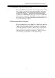
Administrator’s Guide and Operating Instructions Appendix B – Time Lapse Mode Recording Time EDR1600 Time Lapse Mode Recording Time (system storage: 20GB) (Estimated with typical image - low noise level) JPEG Normal (5) day hour min. 20 52 1 17 45 2 14 38 4 8 24 8 16 48 13 1 12 21 17 59 26 2 23 43 11 59 86 23 58 130 11 59 217 11 55 260 23 54 Total Capture Rate (FPS) NTSC PAL 30 25 15 12.5 10 8.3 6 5 3 2.5 2 1.7 1.2 1 1 0.83 0.6 0.5 0.3 0.25 0.2 0.17 0.12 0.1 0.
Administrator’s Guide and Operating Instructions EDR1600 Time Lapse Mode Recording Time (system storage: 20GB) (Estimated with typical image - low noise level) Total Capture Rate (FPS) NTSC PAL 30 25 15 12.5 10 8.3 6 5 3 2.5 2 1.7 1.2 1 1 0.83 0.6 0.5 0.3 0.25 0.2 0.17 0.12 0.1 0.1 day 1 3 5 9 11 18 37 56 94 113 Fine (10) hour min. 9 53 18 14 27 21 21 35 19 10 16 45 11 55 9 30 22 49 23 39 23 28 23 7 22 56 MPEG-1 Normal (5) day hour min.
Administrator’s Guide and Operating Instructions Appendix C – Simulated Keyboard There are situations that the user will be asked to enter a numeric or alphanumeric string. So, a Simulated Keyboard is designed for the user to use the mouse for all the operations. Please refer to the following diagram for the details. Appendix D – Q & A Q: The mouse doesn’t work. A: The mouse must be connected to the system at system startup.
Administrator’s Guide and Operating Instructions Q: How to setup time-lapse recording? A: Please setup the Normal Recording rates for the Cameras at different Time Types. The normal recording rates are also time-lapse recording rates. Q: How to setup event recording? A: Please setup the Alarm Recording rates for the Cameras at different Time Types, the different Actions, and the enable/disable items for the Cameras and the Alarm Inputs. The alarm recording rates are also event-recording rates.
Administrator’s Guide and Operating Instructions Q: How to login to the system if the administrator’s login name and password are lost? A: For the security reason, it’s impossible to retrieve the login name and password once they’re lost. Once the administrator’s login name and password are lost, the only way to re-login to the system is through the backdoor program.
EverFocus Electronics Corp. Head Office: 12F, No.79 Sec. 1 Shin-Tai Wu Road, Hsi-Chi, Taipei, Taiwan TEL: 886-2-26982334 FAX: 886-2-26982380 http:// www.everfocus.com.tw USA Office: 2445 Huntington Drive, San Marino, CA, 91108 U.S.A. TEL: 1-626-844-8888 FAX: 1-626-844-8838 Toll free: 1-888-383-6287 or 1-888-EV-FOCUS http://www.everfocus.