INSTRUCTION MANUAL Mobile Digital Single Channel Recorder EDSR100M V1.0 About this manual Before installing and using this unit, please read this Manual carefully. Be sure to keep it handy for later reference.
Safety Warning WARNING TO REDUCE RISK OF FIRE OR ELECTRIC SHOCK, DO NOT EXPOSE THIS APPLIANCE TO RAIN OR MOISTURE. CAUTION DO NOT REMOVE COVER. NO USER SERVICEABLE PARTS INSIDE. REFER SERVICING TO QUALIFIED SERVICE PERSONNEL. Note: This equipment has been tested and found to comply with the limits for a Class A digital device, The changes or modifications not expressly approved by the party responsible for compliance could void the user's authority to operate the equipment.
Safety Precautions Safety Precautions ?Refer all work related to the installation of this product to qualified service personnel or system installers. ?Do not block the ventilation opening or slots on the cover. ? Do not drop metallic parts through slots.This could permanently damage the appliance. Turn the power off immediately and contact qualified service personnel for service. ?Do not attempt to disassemble the appliance.To prevent electric shock, do not remove screws or covers.
Safety Precautions Safety Precautions The lightning flash with an arrowhead symbol, within an equilateral triangle, is intended to alert the user to the presence of uninsulated ” dangerous voltage ” within the product’s enclosure that may be of sufficient magnitude to constitute a risk of electric shock to persons The exclamation point within an equilateral triangle is intended to alert the user to presence of important operating and maintenance(servicing)instructions in the literature accompanying the ap
Important Safeguards Important Safeguards Read Instruction---All the safety and operating instructions should be read before the init is operated Retain Instructions---The safety and operating instructions should be retained for future reference. Heed Warnings— All warnings on the unit and in the operating instructions should be adhered to. Follow Instructions— All operating and use instructions should be followed Cleaning— Unplug the unit from the outlet before cleaning.
Important Safeguards Important Safeguards and Warnings before Installation For Mobile Digital Single Channel Video Recorder (single HDD) While the DVR is connected to the 12VDC battery of the vehicle, the limited electric current is 3.0 amps with a normal electric current between 1.5~1.0 amps. While the DVR is connected to the 24VDC battery of the vehicle, the limited electric current is 1.5 amps with a normal electric current between 0.7~1.0 amps.
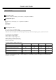
Quick Install Guide Quick Install Guide : 1.Unpack Everything Make sure you have everything you need before you begin the installation. 2.Equipment Required The following tools may help you to complete the installation: •Drill •Screwdrivers •Wire cutters 3. Choosing the Location Choose a location for installation that: •Provide convenient access for installing or removing the hard drive •Allows air to flow around the fan vents. Inadequate or improper air flow can impede proper operation of the unit.
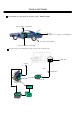
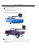
Quick Install Guide Possible Installation Locations Inside the Automobile Vehicle: TOYOTA CAMRY Glove box (inside or underneath) Truck ( Suggest user “ suspend” for mounting option) Passenger seat (underneath) Drive seat ( between seat and wall) Show the wiring on the wiring harness that connects to the electrical system.
Quick Install Guide Possible Installation Locations Inside the Automobile Vehicle: Truck Glove box (inside or underneath) Drive seat ( between seat and wall) or Passenger seat (underneath) ( Suggest user use “support” for mounting option) Show the wiring on the wiring harness that connects to the electrical system.
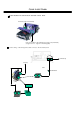
Quick Install Guide Installing the Camera and Monitor The DVR is typically connected to one camera installed inside the car. For installation procedure, refer to the guide that came with the camera you purchased. The Monitor power supply connect from the Automotive adapter(cigarette plug) Monitor and cameras must be purchased separately. LCD Monitor LCD Monitor Connect the Camera Connect the power connector from the camera harness into the CAM ERA POWER OUT jack on the back panel of the DVR.
Quick Install Guide The DVR can be mounted horizontally (suspend or support mounted). Interface Support Suspend Interface Show all the possible ways to mount the DVR. Use the two Z-brackets supplied to mount it in any ways shown.
Quick Install Guide Installing the Hard Drive As following are the figure for the 3.5”and 2.5”HDD. Figure shows 3.5“ HDD Figure shows 2.
Table of Contents 1. Product Overview… … … .… ...… … … … … … … … … … … … … … … … … … … … … … … … … … … … … … … … ..… … … … .. 1 1.1 Feature… … … ...… … .… … .… .… … … … … … … … … … … … … … .… … … … ..… … … … … … … … … … … … … … … … … ..1 1.2 Specifications… … … ....… … … … … … … .… … … … … … … … … … … … ..… … … … .… … … … .… … … … … … … … … … ...2 2. Front & Rear Panels… … … ...… … .… … … … … … … … … … … … … … … ..… … … … … … … … … … … … … … … … … … … ....3 3. Back Panel Connections… … .… … … ...
Product Overview and Features 1. Product Overview The EDSR100M is the industry’s first full- featured digital video recorder designed specifically for use in mobile applications. Superior image quality and ease of use, combined with the ability to withstand high levels of vibration and humidity make the EDSR100M ideal for use in buses, cars, police cruisers, or any other application requiring a rugged digital recorder.
Specifications 1.
Front Panel Keypads 2. Front Panel Keypads 17 1 18 2 3 20 4 5 6 7 8 19 EDSR100M 22 9 10 11 13 12 14 15 16 21 KEY 1 ~ 4 Left/Right Button: Press Up/Down Button: Press or or to move the cursor to the left or right to change the value. 5 ENTER: Press this key to confirm the selection or data changed. 6 BUZZER: Press this key to turn On/OFF the buzzer for all events. 7 LOCK : Press and hold the LOCK button over 3 seconds to lock/unlock the function keys of the front panel.
16 Display: Press this key to switch ON/OFF. Record 002HR Record 002HR Disk:120 GB(0) Disk:120 GB(0) Disk size:120GB 2003/04/24 10:41:00 2003/04/24 10:41:00 Display OFF Display Date/Time And Operation status 17 HDD KEY: Protect HDD without steal 18 Hard Disk Tray: Hard Disk holder for HDD. 19 Display Date/Time, Operation Status, Disk Status. Jog and Shuttle Dial Shuttle : In Playback mode,turn the shuttle dial can fast forward/rewind the picture.
Back Panel Connections 3. Back Panel Connections 6 10 3 8 7 5 4 2 9 1 POWER 1 Power in: The main power in. AUDIO 2 Audio IN : Audio input for recording. Audio OUT : These two audio outputs can be set to “Enable” or “Disable” in Setup Menu. The operation of audio out is as follows: ( Internal circuit ) SW2 OFF / Mute SW1 Playback Audio A Audio OUT Audio IN Operation of SW2 : Operation of SW1 : When in recording or standby mode, the out of SW1 is connected to Audio IN.
Back Panel Connections MONITOR 3 MUX MAIN MONITOR: Video input BNC connector, connected to multiplexer main monitor output. 4 MONITOR : Video output BNC connector connected to main monitor. ( Internal circuit ) SW3 MAIN MONITOR A INTERNAL VIDEO MONITOR OUT When the machine is in Menu, Search or Copy mode, the internal Video is switched to Monitor Out, so that the user can view full screen OSD. In other modes, the Video from multiplexer main monitor will be loop-through to the Monitor Out.
Back Panel Connections RS232 RS232 connector : Connect D-Sub 9 pins connector to RS232 ports for remote control 8 RS485 9 RS485 connector : Cascade multi Digital Video Recorder. 10 FAN: Cooling FAN.
System Connection 4. System Connection 4.1 One Camera Connection. (1) (2) (3) Main Monitor (1 ) :Video out: The Camera Video Output is connected to the Video In at the rear panel. (2 ) : Audio Out: The camera audio output is connected to the audio input terminal at the rear panel. (3) : System Main Monitor Output: The main monitor is connected to the VIDEO OUT 1 BNC connector. Note: Please set the Multiplexer item to OFF .
System Connection 4.2 Multiplexer Connection. Multiplexer MAIN MONITOR OUTPUT (3) VCR IN (2) VCR OUT (1) (4) (1): Multiplexer VCR Out : This connects to the VIDEO IN connector at the rear panel. Main Monitor (2) :Multiplexer VCR In : This connects to the VIDEO OUT 1 connector at the rear panel. (3) :Multiplexer Main Monitor Output: This connects to the MUX. MAIN MONITORIN IN connector at the rear panel. (4) :System Main Monitor Out: Connect the MAIN MONITOR OUTPUT connector to the main monitor.
System Connection 4.3 Quad Connection. ( Quad with VCR in VCR out connector) Quad MAIN MONITOR OUTPUT (3) VCR IN (2) VCR OUT (1) (4) Main Monitor (1): Quad VCR Out: This connects to the VIDEO INPUT connector at the rear panel. (2) : Quad VCR In: This connects to the VIDEO OUTPUT connector at the rear panel. (3) : Quad Main Monitor Out: This connects to the MUX. Main connector at the rear panel. (4) : System Main Monitor Output: Connect the MAIN MONITOR OUTPUT connector to the main monitor.
System Connection 4.4 Quad connection. ( Quad without VCR in VCR out connector) Quad VIDEO OUT (1) (2) Main Monitor (1): Quad Video Out ( to Video Recorder): This connects to the VIDEO INPUT connector at the rear panel. (2): System Main Monitor Output: Connect the MAIN MONITOR connector to the main monitor. Note: Please set the Multiplexer item to OFF .
INSTALLATION 5. Installation (1) Insert a HDD (IDE) for Video Storage The HDD should be set as MASTER. ( Normally the default setting of HDD is Master) Notice: After the hard disk case is inserted into the hard disk tray, be sure to Turn the tray key in lock position. Otherwise, hard disk will not be detected and The System Loading procedure can not be completed. (2) Connect cable for video/audio input and video/audio out, The POWER LED lights if power is normal.
MENU 6. MENU FLOW Turn the Jog dial clockwise or counterclockwise to change setting menu page. ALARM RECORD SETTING MENU ( See page 20 ) CLOCK/LANGUAGE SETTING MENU ( See page 14 ) ALARM RECORD SETTING MENU CLOCK/LANGUAGE SETTING MENU DATE TIME ALARM OPERATION RECORDING SPEED RECORDING QUALITY ALARM – IN TYPE ALARM -RESET TYPE ALARM DURATION TIME : 2003/04 /24 TUE : 13:01:02 MENU LANGUAGE PRE-ALARM OPERATION RECORDING SPEED : ENGLISH : : : : : : ON 002 HR STANDARD N.O. N.O.
MENU 6.1 CLOCK/ LANGUAGE SETTING MENU CLOCK/LANGUAGE SETTING MENU DATE : 2003/04/24 TUE TIME : 13:01:02 : ENGLISH MENU LANGUAGE VERSION: 1.0 (2003/05/26) In CLOCK/LANGUAGE SETTING MENU , we SET (1) DATE : Current date Year: 2000 ~ 2099 Month: 01~ 12 (2) TIME : Current time Hour: 00 ~ 23 Minute : 00 ~ 59 Date: 01~31 Second: 00 ~ 59 (3) MENU LANGUAGE: ENGLISH Left/Right Button: Press Up/Down Button: Press or or 14 to move the cursor to the left or right to change the value.
MENU 6.2 DAYLIGHT SETTING MENU DAYLIGHT SETTING MENU DAYLIGHT SAVING: OFF START ON JAN 1ST MON FROM 00:00 TO 00:00 END ON JAN 1ST MON FROM 00:00 TO 00:00 In DAYLIGHT SETTING MENU , we define: (1) DAYLIGHT SAVING: Select “ON” or “OFF” while the daylight saving time function is enabled or not.
MENU 6.
(4) Speed : When SPEED FORMAT is set to HOUR, the recording speed can be set from 2/3 (NTSC/PAL)HR to 960HR. When SPEED FORMAT is set to IPS, the recording speed can be set from 1~60/1~50(NTSC/PAL)IPS. (5) QUALITY: Picture Quality There are six quality levels for recording LOWER LOW BASIC STANDARD HIGH SUPERIOR : : : : : : 15 KB 20 KB 25 KB 30 KB 35 KB 40 KB (6) SET: Set “ON” when using timer recording.
MENU 6.4 NORMAL RECORD SETTING MENU NORMAL RECORD SETTING MENU SPEED QUALITY MULTIPLEXER DISK FULL : : : : 002 HR STANDARD OFF REWRITE In NORMAL RECORDING MENU, we define (1) SPEED : Recording Speed The user can select the record ing speed from 2/3 (NSC/PAL) HR to 960 HR.
MENU (3) MULTIPLEXER: ON/OFF : The user can select Multiplexer connection or One Camera connection ON : The video input from MUX MAIN MONITOR connector at the rear panel will be looped through to the main monitor out when the recorder is not in MENU mode. OFF : The main monitor output is similar to the video out connector. (4) Disk Full: STOP : When the disk is full, the machine will STOP recording.
MENU 6.5 ALARM RECORD SETTING MENU ALARM RECORD SETTING MENU ALARM OPERATION RECORDING SPEED RECORDING QUALITY ALARM – IN TYPE ALARM -RESET TYPE ALARM DURATION TIME : : : : : : PRE-ALARM OPERATION RECORDING SPEED : ON : 003 HR ON 003 HR STANDARD N.O. N.O. 05 SECS In ALARM RECORDING MENU, we define (1) ALARM OPERATION : ON : Records when alarm occurs. OFF : Does not record when alarm occurs. (2) RECORDING SPEED : The recording speed in alarm duration. The max. recording speed is 2/3 (NTSC/PAL) HR.
MENU (4) ALARM – IN TYPE : N.O. : Normal Open, N.C. : Normal Close (5) ALARM - RESET TYPE: N.O. : Normal Open, N.C. : Normal Close (6) ALARM DURATION TIME : Alarm recording starts from the beginning of alarm and stops at the end of the duration. The max. duration is NON - STOP, the min. duration is 5 Seconds. (7) PRE-ALARM OPERATION : ON : Record the picture in pre -alarm recording speed in pre-alarm period. OFF : No pre -alarm recording before alarm occurs.
MENU Note: Alarm Connectors (DB-15) The alarm connector, figure 1, is used to provide one sensor alarm input for each camera input. For easy operation, an alarm extension board, figure 2, is provided to connect to the alarm connector. 1 8 15 Each alarm input requires two wires, one wire connects to the desired alarm input pin, the second wire connects to the multiplexer ground. The alarm signal assignment is shown at the following table, table 1.
MENU (a.
MENU (c) Alarm in and alarm reset There is 1 alarm sensor in for 1 channel and 1 alarm reset in, the alarm input can be set to Normally Open or Normally Closed by user. ALARM CIRCUIT SENSOR 1 8 15 2 1 9 ALARM RESET Alarm in There is one alarm input. Please connect the alarm input in the same sequence as the camera input BNC. When alarm signal comes in, the Digital Video Recorder will do the following: 1. Display Alarm Message 2. Turn on the buzzer if the buzzer setting is on.
MENU 6.6 BUZZER SETTING MENU BUZZER SETTING MENU BUZZER ALARM – IN RECORD -IN DISK FULL VIDEO LOSS TIMER : ENABLE : : : : : ON ON ON ON ON In BUZZER SETTING MENU, we SET the buzzer ON/OFF under the following conditions: (1) BUZZER : ENABLE: Turns the buzzer on. DISABLE: Turns the buzzer off. User can press Enter button to enable/disable in Record/Playback mode . (2) ALARM – IN : ON, the buzzer will sound when the alarm occurs.
MENU 6.7 ARCHIVE SETTING MENU ARCHIVE SETTING MENU PICTURE SIZE TIME STAMP TIME STAMP POS WATER MARK WATER MARK POS MULTIPLEXER : : : : : : 720x576 ON BOTTOM ON BOTTOM NONE (1) PICTURE SIZE : Selects picture size for copying image to CF card Big size:720x576 Small size:352x288 (2) TIME STAMP : ON: The time stamp will show on the picture when copying image to CF card. OFF: The time stamp will not show on the picture when copying image to CF card.
MENU 6.8 RS232/RS485 SETTING MENU RS232/RS485 SETTING MENU RS232/RS485 RS232/RS485 ID BAUD RATE PARITY DATA BIT STOP BIT : RS232 : 01 : 9600 : NONE :8 :2 In the RS232/RS485 SETTING MENU, we define (1) RS232/RS485: Choose RS232 or RS485 for activated. (2) RS232/RS485 ID: This entry is used to assign each device with its own ID code, when more than on unit is used in one system through RS232/RS485.
MENU 6.9 SYSTEM SETTING MENU SYSTEM SETTING MENU PLAY WITH AUDIO 1 PLAY WITH AUDIO 2 PASSWORD ENABLE PASSWORD FIELD CODE LINE DISK RENEW SYSTEM UPDATE LOAD DEFAULT CF RENEW(FAT16) : : : : : : : : : NO NO OFF 888888 12 NO NO NO NO (1) PLAY WITH AUDIO 1 PLAY WITH AUDIO 2 : ON/OFF : Play back with or without audio. (2) PASSWORD ENABLE : YES/NO : User can set the PASSWORD ON or OFF to enter the system setting menu. YES: Selects the PASSWORD to enter the system setting menu .
MENU (4) FIELD CODE LINE : When the system is connected to the Multiplexer, it is used to adjust the field code of the Multiplexer. The values: 00~20 The default value is 13, it is suitable for most of the multiplexers. If the field code line appears on the top of each playback channel, decrease the value. If multiplexers can not playback properly ,increase the value. (5) DISK RENEW : YES/NO : Activates the Renew HDD option.
MENU (7) LOAD DEFAULT : LOAD DEFAULT NO YES Press NO to load default and Exit. LOAD DEFAULT NO YES Press YES to load default value. (8) CF RENEW: Two of modes for choice, YES or NO. CF RENEW NO YES CF RENEW NO NO: will not format CF card YES: will format CF card YES Left/Right: Press Up/Down: Press or or to move the cursor to the left or right to change the value.
Recording 7.1 INSTANT RECORDING Press Record key to start the recording immediately. Video out When pressed, the pictures being monitored will be recorded in the HDD. REC •The recording rate and recording quality are set in the Record Set menu RECORD 002 HR • “ REC ” button light up in the operating display Press Stop key to stop recording. • Stop key can be activated only in recording mode.
Recording 7.2 ALARM RECORDING The monitor image will automatically record when alarm occurs and stops recording at the end of the alarm duration period. Instant recording and timer recording will stop when an alarm occurs. MENU Press MENU key and turn the jog dial to select the ALARM RECORDING SETTING MENU. RECORDING OPERATION: ON: Enables alarm recording, OFF :Disables alarm recording. RECORDING SPEED: Set the recording speed when alarm occurs.
Playing Back 8.1 NORMAL PLAYBACK (1) Playback Press the PLAY key to start playing back the stored image/audio from the last SEGMENT. PLAY Press the REV.PLAY key to start reverse playing back the stored image/audio from the last segment. REV.PLAY (2) STOP Press the STOP key to stop playing back. STOP (3) Fast Forward/Reverse Playback Press the PLAY key to start playing back. PLAY Turn the shuttle dial clockwise and fast forward playback starts.
Playing Back (4) Slow Forward/Reverse Playback Press PAUSE key to freeze the playing back picture. PAUSE Turn the shuttle clockwise and slow forward playback starts. The speed will show on the LCD at the corner of the screen. >> 1/2, 1/4, 1/6, 1/8, 1/10, 1/16, 1/32 Turn the shuttle counterclockwise and slow reverse playback starts. The speed will show on the LCD at the corner of the screen.
Playing Back 8.2 SEARCH PLAYBACK (1) Segment Search Playback Press the SEARCH key to enter the Search menu. SEARCH SEARCH MENU BY SEGMENT LIST BY ALARM LIST BY DATA TIME Press the select file search. keys to move the cursor to BY SEGMENT LIST and press ENTER key to SEGMENT SEARCH 1 2 3 Alarm Timer Timer 2002/04/24 19/03/29 2002/04/25 12/30/30 2002/05/20 12/00/00 Alarm:ALARM RECORD Timer: TIMER RECORD Press the keys to move the cursor to the segment you want to playback.
Playing Back (2) Alarm Search Playback Press SEARCH key to enter the Search menu. SEARCH SEARCH MENU BY SEGMENT LIST BY ALARM LIST BY DATE TIME Press the keys to move the cursor to BY ALARM LIST and press ENTER key to select alarm search. ALARM SEARCH 1 Alarm 2 Timer 3 Timer 2002/04/24 19/03/29 2002/04/25 12/30/30 2002/05/20 12/00/00 Alarm : PRE-ALARM RECORD Timer : TIMER RECORD Press the keys to move the cursor to select the alarm image to be played back.
Playing Back (3) Date/Time Search Playback Press SEARCH key to enter the Search menu. SEARCH SEARCH MENU BY SEGMENT LIST BY ALARM LIST BY DATE/TIME Press the select file search. keys to move the cursor to BY DATE/TIME and press ENTER key to DATE/TIME SEARCH YEAR/MM/DD HH:MM:SS 2002 04 24 19 03 35 Press the keys to move the cursor. Press the keys to increase/decrease the data. Press Enter and the playback starts from the date/time set in the menu.
COPY 9. COPY Insert a Compact Flash card into the Compact Flash slot on the front panel. When inserting the Compact Flash card, make sure that the direction of insertion is correct. EDSR100M 9.1 STILL IMAGE COPY Press the PLAY key to start playing back. PLAY Press the PAUSE key to freeze the picture. PAUSE Turn the jog dial clockwise or counterclockwise to move to your desired image of choice . COPY While the image to be displayed as your desired image of choice , press the COPY key.
COPY 9.2 COPY TO MOVIE FILE Press the PLAY key to start playing back. PLAY Press COPY key and then the copy menu appears. COPY COPY TO MOVIE FILE Press COPY Press PLAY Press PAUSE Press SEARCH Press STOP To Step Copy To Continue Copy To Stop Continue To End Copy To End Play Press PLAY key to continue Copy Movie File.
COPY PAUSE SEARCH Press the PAUSE key to stop continue copy. Press SEARCH key to end copy. Press STOP key to end play. STOP Notice: Copied images are stored as a movie picture. Copied files are saved as .MOV file. Use QuickTime to play the retrieved .MOV files. You may download QuickTime at www.apple.com. The playback version for QuickTime is free.
Interface Specifications RS232 This Digital Single Channel Recorder may be controlled by a computer or a terminal via the standard D-SUB 9-pin RS-232 connector.
Interface Specifications 10.2 Remote Control Protocol A computer or a terminal can be used to control the unit by sending the packet as following. ========================================================= Digital Video Recorder 485/232 Control Code Protocol ========================================================= 1-1.
2-1. The format of message packet is as follows: Length Byte (Prefix: 0x86, 0x87, or 0x88 ..... ) Receiver ID high byte Receiver ID low byte Opcode Byte Data Byte1 Data Byte2 Data Byte3 . . Checksum Byte 2-2. Length Byte This Length Byte is also a prefix. Bit7 must be 1. EX: 0x87 ==> this packets has 7 bytes length. ( not included Length byte itself ) 2-3. Receiver ID 1).
2-4. Opcode Byte & Data bytes 2-4-1. OPcode -----------------------------------------OPcode Data1 Function -----------------------------------0x4B Keycode A remote key pressed ------------------------------------------ 2-4-1. A remote key pressed (OPcode=0x4B) --------------------------------Data1 Key -----------------------------0x00 key 'LEFT' 0x01 key 'RIGHT' 0x02 key 'UP' 0x03 key 'DOWN' 0x04 key 'ENTER' 0x05 key 'BUZZER' 0x06 key 'LOCK' 0x07 key 'MENU' 0x08 key 'REC' 0x09 key 'REV.
Remote Controller 11. Remote Controller (Optional) The remote controller is an accessory to enhance the handy operations of digital video recorder (Figure 1). You can do all the settings and operations by the remote controller. The effective distance is up to 10 meters without any obstacles. The keypad functions are as same as the front panel of the digital video recorder .
Appendix-A 12. APPENDIX- A/Time Lapse Mode Recording Time 12.1 When Recording with an 80-GB HDD Lower Low Basic Standard High Superior (Estimated with typical image-low noise level) NTSC Recording Speed (Hour) 2 6 12 24 48 72 96 168 480 720 960 : 15 kB : 20 kB : 25 kB : 30 kB : 35 kB : 40 kB (system storage:80GB) Recording Rate (field/Sec) 60 15 8.571 4.615 2.4 1.622 1.224 0.706 0.249 0.166 0.125 PAL Recording Recording Speed Rate (Hour) (field/Sec) 3 50 6 16.667 12 10 24 5.556 48 2.941 72 2 96 1.
Appendix-A 12.2 When Recording with a 160-GB HDD Lower Low Basic Standard High Superior (Estimated with typical image-low noise level) PAL Recording Recording Speed Rate (Hour) (field/Sec) 3 50 6 16.667 12 10 24 5.556 48 2.941 72 2 96 1.515 168 0.877 480 0.311 720 0.207 960 0.
Appendix-B 13. APPENDIX-B/SECURITY LOCK SETTING LOCK LOCK Press LOCK key during record mode, then all the keys on the front panel will be locked. (Password must be Enable on System Setting Menu) Press LOCK key, the system will ask for the password. If you enter a correct password, the locked keys will be released.
EverFocus Electronics Corp. Head Office: 12F, No.79 Sec. 1 Shin-Tai Wu Road, Hsi-Chi, Taipei, Taiwan TEL : 886-2-26982334 FAX : 886-2-26982380 USA Office: 2445 Huntington Drive, San Marino, CA 91108, U.S.A.