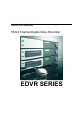
Instruction Manual 16/9/4 Channel Digital Video Recorder EDVR SERIES
EVERFOCUS ELECTRONICS CORPORATION EDVR SERIES Instruction Guide 2005 EverFocus Electronics Corp www.everfocus.com All rights reserved. No part of the contents of this manual may be reproduced or transmitted in any form or by any means without written permission of the Everfocus Electronics Corporation.
Federal Communication Commission Interference Statement This equipment has been tested and found to comply with the limits for a Class B digital device, pursuant to Part 15 of the FCC Rules. These limits are designed to provide reasonable protection against harmful interference in a residential installation. This equipment generates, uses and can radiate radio frequency energy and, if not installed and used in accordance with the instructions, may cause harmful interference to radio communications.
CE Declaration This equipment has been tested and found to comply with the limits for a CE Class A digital device. The changes or modifications not expressly approved by the party responsible for compliance could void the user’s authority to operate the equipment. In a domestic environment this product may cause radio interference. In which case the user may be required to take adequate measures.
TABLE OF CONTENTS 1. PRODUCT OVERVIEW ..............................................................................................1 1.1 Features.................................................................................................................1 1.2 Specifications.........................................................................................................2 1.3 Front Panel Keypads .............................................................................................4 1.
4.1 Instant (N) Recording Setup ................................................................................59 4.2 Schedule Recording Setup ..................................................................................60 4.3 Event Recording Setup ........................................................................................60 5. PLAYBACK OVERVIEW...........................................................................................63 5.1 Basic Playback .................................
APPENDIX B: ALARM BOARD CONFIGURATION ..................................................124 APPENDIX C: RJ45 (RS485) PIN ASSIGNMENT......................................................127 APPENDIX D: LAPSE MODE RECORDING TABLE .................................................128 APPENDIX E: INSTALLATION STEPS OF NERO INCD SOFTWARE......................132 INDEX .........................................................................................................................141 TROUBLESHOOTING ......
Safety Warning WARNING To reduce risk of fire or electric shock, do not expose this appliance to rain or moisture. CAUTION Do not remove cover. No user serviceable parts inside. Refer servicing to qualified service personnel. Note: This equipment has been tested and found to comply with the limits for a Class A digital device, The changes or modifications not expressly approved by the party responsible for compliance could void the user's authority to operate the equipment.
Safety Precautions Refer all work related to the installation of this product to qualified service personnel or system installers. Do not block the ventilation opening or slots on the cover. Do not drop metallic parts through slots. This could permanently damage the appliance? Turn the power off immediately and contact qualified service personnel for service. Do not attempt to disassemble the appliance. To prevent electric shock, do not remove screws or covers.
Safety Precautions Read Instruction All the safety and operating instructions should be read before the unit is operated. Retain Instructions The safety and operating instructions should be retained for future reference. Heed Warnings All warnings on the unit and in the operating instructions should be adhered to. Follow Instructions All operating and use instructions should be followed. Cleaning Unplug the unit from the outlet before cleaning.
Chapter 1 1. Product Overview The latest EverFocus digital video recorder generation is based on MPEG-4 compression technology, resulting in enhanced recording capacity and improved network image transmission speed with high image quality. Comprehensive features and extended event recording settings enable the almost universal application of this DVR series. 1.
Remote Firmware Upgrade function System diagnostic feature alerts users of HDD or system problems via Email or alarm output 1.
Timer Watch Dog Timer Title VGA USB Ethernet Archive RS-485 Power Source Power consumption Dimension Weight Operating Temperature Built-in real time clock and Auto Time Synchronization with global NTP server through Internet Yes 12-characters title for each camera Yes Yes, 2 x USB2.0 interface device. 1 for archiving & 1 for mouse. Yes, RJ45 connectors for network communication USB 2.0 port for archiving to memory stick or external DVD burner (EPR200) D series: built-in 3.
1.3 Front Panel Keypads Keys: 1 REC Press this key to start instant recording. 2 STOP Press this key to stop recording and playing back. 3 PLAY Play Back. 4 PAUSE Press this key to pause the playback picture. 5 SEARCH Press this key to enter the SEARCH MENU. 6 COPY Opens image export menu. In playback mode, the current playback position is stored as image export start position. 7 ENTER Press this key to enter items, or jump to next subentry in the menu setting.
9 SELECT On live view, press this key to assign a camera to a multi-screen or to adjust single screen display properties. In menus, press this key to select certain features. 10 MODE Switch PIP, 4, 7, 9, 10, 13 and 16 displays in Live and Playback modes. 11 ZOOM In full screen mode, 2x electronic zoom. Zoom screen can be moved through JOG. Enter key changes the direction. Pressing the zoom key again switches the electronic zoom off. In multiscreen mode: Image orientation adjustment.
13 CALL Press this key to enter and set up CALL MENU. 14 Menu Press this key to enter MAIN SETUP MENU or to exit from any submenu. 15 Shuttle and Jog Dial Shuttle: In the Playback mode, turn the Shuttle dial to fast forward/rewind the video. In the Pause mode, turn the Shuttle dial to slow forward/rewind the video. In the event list, turn the Shuttle to change pages. Jog Dial: In the Pause mode, turn the Jog dial to forward/rewind the video frame by frame.
1.4 Back Panel Connections For models: EDVR16D1/F1, EDVR16D2/F2, EDVR9D1/F1, EDVR4D1/F1 For model: EDVRD3 POWER 1 Main Power plug Connect power jack (AC 100~240V). 2 Power Switch Switch DVR on or off. MONITOR 3 MAIN MONITOR This connector is used for the main monitor display, a number of different display modes may be selected for viewing. 4 CALL MONITOR This connector is used for the call monitor. This monitor can only display a full screen, but not able to enter Setup Menu.
VIDEO IN 5 16 CH: VIDEO OUT (1~16): BNC connectors for video looping out 1~16. VIDEO IN (1~16): BNC connectors for video input 1~16. 9 CH: VIDEO OUT (1~9): BNC connectors for video looping out 1~9. VIDEO IN (1~9): BNC connectors for video input 1~9. 4 CH: VIDEO OUT (1~4): BNC connectors for video looping out 1~4. VIDEO IN (1~4): BNC connectors for video input 1~4. ALARM INPUT/OUTPUT 6 ALM-INPUT Normal open or normal close type alarm signal inputs. The Alarm Input can be selected as normal open (N.O.
VGA 10 VGA Connect to the monitor that has VGA input. REMOTE CONTROL (extension cable is optional) 11 Remote Control Connector for IR extension cable that has an IR remote control receiver. AUDIO 12 Audio IN Audio inputs 1~4 for recording, and it can be enabled by setting to “YES” or “NO” in the RECORD SETUP MENU. Audio OUT Connect an audio output to a monitor or other device. Audio 1 corresponds to CH 1, audio 2 corresponds to CH 2, audio 3 corresponds to CH 3 and audio 4 corresponds to CH 4.
1.5 Monitor Display The status information of the cameras or machine will show up, and be located at different places on the screen. 1. Channel tag A channel tag indicates the channel name of the screen. 2. Event sign Event signals which are small icons with a capital letter and red background show the events on each screen. There are a total of 6 different signals: A Alarm event. Alarm event shows on a channel if an ALARM is enabled for that camera in the ALARM SETUP MENU and an alarm is triggered.
The last display on the screen has a “*” sign in the top-middle. The S sign will replace the “*” in the display when sequence occurs. Note: Sequence is invalid when the multi-screen display is showing all cameras. T Temperature indication. This shows if the hard drive’s temperature is overheated. Overheat temperature is determined in HDD TEMPERATURE of WARNING SETUP MENU. F Fan fail indication. This shows when the fan fails to work normally.
4. Record status bar The record status bar appears when you enable a status bar on the screen. There are four parts: current date, record status, event, and current time. Current Date Record Status Event Current Time Audio Ch HDD/Fan Status 1. Current date The current date which is set in the TIME/DATE SETUP MENU. 2. Record status While the unit is recording, current HDD and percentage is displayed. e.g: “R01 16%”: currently recording on HDD 1, 16% full. 3.
Chapter 2 2. Installation The installations described below should be done by qualified service personnel or system installers. 2.1 Packing Please check accessories in the packing before installation. 2.2 System Floorplan Please refer to the following diagrams for the system connections. Note: Monitor and Camera must be purchased separately. Diagram 2.
2.3 Basic Wiring Instructions 1. Power Connect the power source or adapter into the power socket. 2. Cameras Connect each cameras video output to the video input on the digital video recorder shown in diagram 2.1. Note: At least one camera (CH 1) must be connected before the system is running for the auto detection of video standard to take effect. 3. Audio Input The camera audio output or Microphone is connected to the audio input terminal at the rear panel. 4.
9. Call Monitors Connect the call monitor output connectors to a call monitor. The call monitor display selected live cameras in full screen format. Note: The call monitor will only display one full screen camera at a time. 2.4 Final Install Process Once you have completed the basic wiring installation and the hard disk drive installation you are ready to turn on the DVR. Simply plug the power source you installed earlier. The POWER LED lights will light up if power is normal.
Chapter 3 3. DVR Menu Setup Assuming you have completed the first two chapters of this manual. You are now ready to begin setting up the digital video recorder. The following chapter will walk you through the detailed DVR Menu step by step and how to set the DVR for your specific application. To begin this process, press the MENU key. Once inside the main menu you will find there are 12 setup option pages as follows. Press the MENU key to enter or exit the MAIN SETUP MENU.
3.1 Time/Date Setup Menu Diagram 3.2 Diagram 3.2 is a screen shot of the TIME/DATE SETUP MENU. This menu is used to set up the correct time and date for your region of the world. You are able to setup daylight savings as well as synch it with an internet based time server. In the TIME/DATE SETUP MENU the following fields are defined as follows: 1. TIME FORMAT This field represents the time format on the DVR. You can select between 12 HOUR and 24 HOUR format. 2.
3. DATE FORMAT This field represents the date format on the DVR. To change this, simply use the Jog Dial on the DVR. There are three date formats to select from: YYYY-MM-DD, MM-DD-YYYY and DD-MM-YYYY. 4. DATE This field represents the date on the DVR. To change this, simply use the Jog Dial on the DVR. The date is represented as follows: Year: 2000~2037 / Month: 01~12 / Date: 01~31 (Day of Week) 5. DAYLIGHT SAVING This field represents the daylight savings on the DVR.
To set the starting time change of daylight saving time: Choose the “FROM” time and “TO” time when daylight savings starts. 7. END TIME To set the end time of daylight saving time. To set the end month of daylight saving time: Dial the jog to set the end month. JAN FEB MAR APR MAY JUN JUL AUG SEP OCT NOV DEC To set the end week of daylight saving time: Dial the jog to set the end week. 1 ST 2 ND 3 RD 4 TH LAST To set the end date of daylight saving time: Dial the jog to set the end date.
c) In the Dos Prompt, type “ping pool.ntp.org” to find out the IP address of an NTP Server. Diagram 3.3 10. TIME ZONE You can set the time zone that the DVR adjusts to when updating from the time server.
DAY WEEK MONTH 3.2 Camera Setup Menu Diagram 3.4 Diagram 3.4 is a screen shot of the CAMERA SETUP MENU. This menu will walk you through setting up the Camera Recording Speeds, Camera titles, PTZ ID, covert modes, and recording quality. In the CAMERA SETUP MENU the following fields are defined as: 1. TITLE The title setting allows you to assign a title to each camera input. Each channel supports a title with up to 12 characters.
3. INSTALL/COVERT For installation of camera; select “ON” to enable a camera, and “OFF” to disable it. Please make sure to stop recording before making a change to INSTALL. To take full advantage of the record abilities, switch any unused camera ports to OFF in this section. For COVERT, select “ON” to disable a channel screen in live mode. However, the image will still be recorded, and can be played back by user who has playback rights. Covert channels will not show up in the sequence mode.
360x240 Video Source Simple: Complex: Average size per image Lower: 1.76KB 4.56KB Low: 1.87KB 4.87KB Basic: 1.97KB 5.46KB Standard: 2.38KB 6.51KB High: 2.67KB 7.08KB Superior: 3.63KB 9.02KB Note: Since the compression ratio of MPEG4 fully depends on the variation and complexity of the recorded video, the tables above are for reference only. 6. REC SPEED & ACTION: TP Scheduled recording time 1~8 which can be set in the SCHEDULE SETUP MENU.
Example: EDVR9F1/D1 with 12 installed cameras, at 720 x 240 resolution: 60 IPS / 12 cameras = 5 IPS Therefore the maximum adjustable recording rate per camera is 5 IPS. EVENT IPS recording rate for motion or alarm events. Event record speed can be set from 1 to 30 IPS (25 for PAL) or “OFF”. Note: In order to activate a new record speed, you need to disable all current record actions and then turn them back on. ACTION Set “ON” to activate TP of motion action. Set “OFF” to disable TP of motion action.
7. SUMMARY Diagram 3.5 All cameras’ statuses are shown in the SUMMARY table. The table is only to check camera overall statuses, not for changing them. Use the Jog to change which option you wish to check. Note: The SUMMARY table also exists in ALARM, MOTION and VIDEOLOSS SETUP MENU. All of these SUMMARY tables are also for checking particular overall statuses, not for setting. 8.
3.3 Record Setup Menu Diagram 3.6 Diagram 3.6 is a screen shot of the RECORD SETUP MENU. This menu is for setting up the options for recording. In the RECORD SETUP MENU the following fields are defined: 1. RECORD AUDIO YES: Audio will be recorded when machine is recording and a microphone is present. NO: Audio will not be recorded when machine is recording. 2. TIME STAMP ON: The time stamp will be recorded on the video and picture when recording.
5. RESOLUTION The resolutions for NTSC are 720x480, 720x240 (default) and 360x240. The resolutions for PAL are 720x288, 720x576 (default) and 360x288. NOTE: Changing the resolution will determine the amount of IPS the DVR will support. Model D1/F1 D2/F2 D3 6.
3.4 Alarm Setup Menu Diagram 3.7 Diagram 3.7 is a screen shot of the ALARM SETUP MENU. An alarm is defined as an electronic or mechanical device that sends a warning signal under specific circumstances. In this case the signal triggers the recorder to start recording the alarmed event. This menu contains all the alarm operations and options needed to successfully complete an alarm recording. In the ALARM SETUP MENU the following fields are defined: 1.
3. LOG YES: Select YES if you wish to record Alarm Events in the Log. NO: Select NO if you do not wish to record Alarm Events in the Log. 4. ACTIVE CAMERA This field is to activate camera you want to have the alarm enabled too. For example if you had an external motion detector on camera one you would set this option to camera one. The Default setting is the same camera number as the current alarm. To change this, simply use the Jog Dial on the DVR. 5.
11. MAIN MON: Display on main monitor when an alarm occurs. NO CHANGE: No change on the main monitor display when an alarm occurs. FULLSCREEN: A full screen of the active camera will display when an alarm occurs. 12. CALL MON: Display on a call monitor when an alarm occurs. NO CHANGE: No change on the call monitor display when an alarm occurs. SEQUENCE: Display in sequence mode on call monitor when an alarm occurs, according to sequence duration set in Camera Setup Menu.
3.5 Motion Setup Menu Diagram 3.8 Diagram 3.8 is a screen shot of the MOTION SETUP MENU. We define motion as a change of pixilation in the field of view, which is detected by the digital video recorder and triggers the recorder to start recording. This menu is for setting up the digital recorder for motion recording on a per camera basis. In the MOTION SETUP MENU the following fields are defined as follows: 1. MOTION This field is to turn motion detection on or off. The default value is DISABLE.
3. LOG YES: Select YES if you wish to record Motion Events log to the HDD. NO: Select NO if you do not wish to record Motion Events log to the HDD. 4. DURATION The amount of time a motion event will record - from 1 sec to 99 seconds. The default value is 5 seconds. To change this, simply use the Jog Dial on the DVR. 5. ALARM OUTPUT This will transmit a signal to another device.
12. SUMMARY Dial Jog to change items in the SUMMARY table. All alarm’s statuses are shown in SUMMARY tables. These tables are for checking alarm overall statuses, not for changing them. 13. MOTION AREA Enter a desired channel and press SELECT or middle mouse button to edit a motion area. MOTION must be set as “Enable” before entering the motion detection area. In the motion edit mode: The default motion area of each camera is entire screen which displays in light green.
3.6 VIDEOLOSS Setup Menu Diagram 3.9 Diagram 3.9 is a screen shot of the VIDEOLOSS (Video Loss) SETUP MENU. VIDEOLOSS event is caused by no video signal input for the channel. Usually it happens when no power supply for the camera or the camera fails. How to set up system response for VIDEOLOSS case is introduced in this section. In the VIDEOLOSS SETUP MENU the following fields are defined as follows: 1. VIDEOLOSS: ENABLE: Enable video loss detection. DISABLE: Disable video loss detection. 2.
signal 3 transmits and 4 = output signal 4 transmits. To change this, simply use the Jog Dial on the DVR. (Only EDVR16D3 model has 4 alarm outputs, all others have only 1 alarm output). 5. ALARM EMAIL: Select “YES” for sending an email when Video Loss event occurs. The email address can be set in the NETWORK SETUP MENU. 6. BUZZER: Audible alarm buzzer. ENABLE: To enable a VIDEOLOSS buzzer. DISABLE: To disable a VIDEOLOSS buzzer. 7. ALARM NETWORK: YES: Enable alarm network. NO: Disable alarm network.
3.7 Network Setup Menu Diagram 3.10 Diagram 3.10 is a screen shot of the NETWORK SETUP MENU. This menu is for setting up the configurations for networking to the DVR. There are 6 subentries: CONFIG, ALARM, EMAIL, PASSWORD, PPPoE and DDNS. Each of them should be set up connecting the DVR to the network. For more detail about network setup, please refer to Chapters 10~13 of this manual to fully understand how to setup your network for this DVR.
PPPoE: This is a DSL connection application, ISP will ask user to input user name and password. When you choose this option, please go to PPPoE configuration menu for setting PPPoE configuration. 2. IP Address This field shows the current IP Address for the DVR. A Fixed IP address does not change and must be set manually. To change this, simply use the Jog Dial on the DVR. When DHCP is selected, the DHCP server will assign this value automatically.
9. DATA PORT The default data transmitting port number is 37260. User can change it to different port number for data transfer between DVR and client PC. Note: If you wish to have multiple users log into the DVR, please open a range of ports on your router. For example if you want to allow 4 clients to login through the default port 37260, you should open the port range 37260-37263 on your router. 10. BW CONTROL This configuration allows user to control the bandwidth of DVR. 11.
1. PROTOCOL: Select which communication protocol to use with Alarm servers or Alarm receiving clients. TCP: communicate with client via TCP protocol. UDP: communicate with client via UDP protocol 2. PORT NUMBER Set the communication port with Alarm server. 3. UNIQUE ID Set the ID number of your DVR to Alarm server. 4. SERVER 1 Assign the IP address of Alarm server 1. 5. SERVER 2 Assign the IP address of Alarm server 2. 6. SERVER 3 Assign the IP address of Alarm server 3. 3.7.3 EMAIL Diagram 3.
In the EMAIL of the NETWORK SETUP MENU, we define: 1. SMTP SERVER Assign the SMTP (e-mail) server’s name. Note: For more reliable email service, use the server’s IP address. 2. PORT NUMBER Assign the port number for SMTP server. The default port is 25. 3. AUTHENTICATION Select “YES”, if the SMTP server requires Authentication (user name / password) 4. USER Input the login user ID if the SMTP server requires Authentication. 5. PASSWD Input the password if the SMTP server requires Authentication. 6. RECEIV.
3.7.4 PASSWORD Diagram 3.13 In the PASSWORD of the NETWORK SETUP MENU, we define: Name/Password/Level: This category is to set up the users that will log into the network. Please remember that this portion of the Network setting menu is set up in column format. The default User Name = ADMIN The default Password = 11111111 (numeric only) To change this, press Enter to move to each character and use the Jog Dial on the DVR to change each character. There are 3 level types: 1.
3.7.5 PPPoE Diagram 3.14 In the PPPoE of the NETWORK SETUP MENU, we define: 1. USER User name that is provided by ISP for PPPoE Connection 2. PASSWD Password that is provided by ISP for PPPoE connection 3. PRIMARY DNS IP address of DNS server that is provided by ISP. 4. SECONDARY DNS If your ISP provides you with a secondary DNS address, please set it in here. NOTE: Please complete all settings in the PPPoE Setup Menu before changing IP CONFIG to PPPoE in the CONFIG options.
3.7.6 DDNS Diagram 3.15 In DDNS of the NETWORK SETUP MENU, we define : 1. SERVER DDNS provider (example: www.dyndns.com) 2. USER User name of the account. 3. PASSWD Password of the account. 4. RECORD ID Identity tag used by certain DDNS providers 5. FQDN The domain name of this account.
EXAMPLE: A user applied for a DDNS account from http://www.dyndns.com User name: TEST Password: TEST Domain name ethin.dyndns.org. Users can connect to DVR that uses dynamic IP address by entering the domain name “ethin.dyndns.org” in IE browser. They do not have to know the IP address. NOTE: This domain name is only an example. The DDNS account that the user applies will likely differ from this example. See Chapter 13 for more details 3.8 Schedule Setup Menu Diagram 3.16 Diagram 3.
1. DAY This field represents the day of the week you wish to set the timer record for. Initially it is set to DLY as default. You may choose from MON-SUN as well as WDAY, WEND, and DLY. To change this, simply use the Jog Dial on the DVR. MON (Monday), TUE (Tuesday), WED (Wednesday), THU (Thursday), FRI (Friday), SAT (Saturday), SUN (Sunday). WDAY: Weekday, from Monday to Friday. WEND: Weekend, Saturday and Sunday. DLY: Daily, everyday of the week. 2.
3.9 Disk Setup Menu Diagram 3.17 Diagram 3.17 is a screen shot of the DISK SETUP MENU. This menu is for viewing Disk information and formatting the disks. For initial setup or major setup changes we recommend formatting the Hard Disk. In the DISK SETUP MENU the following fields are defined as follows: 1. DISK INFORMATION Select disk information, it is selectable from 1 up to 50 disks, in intervals of 4. The total number of hard drives varies by model. 2. DISK VIDEO DELETE Press SELECT to start delete.
Note: System will ask you to stop recording if you try to delete the disk while still in the record mode. 3. THERMOMETRIC SCALE Select CELSIUS or FAHRENHEIT for thermometric scale of the disk. 4. NO Shows the hard drive number. The number of disks displayed may vary depending on the model. Note: For EDVR16D3 model, up to 50 hard drives can be added through SCSI port. 5. SIZE Storage capacity of the hard drive. 6. °C (or °F) Current temperature of the hard drive in Celsius or Fahrenheit degrees. 7.
3.10 Control Setup Menu Diagram 3.18 Diagram 3.18 is a screen shot of the Control Setting Menu. This menu is to define the settings for DVR remote control through serial interface in the RS232/RS485 menu. The following fields are defined in the Control Setting Menu: RS232: 1. RS232 Baud Rate This field is to set the speed at which is used to transmit instruction or information through the RS232 port on the DVR.
4. RS232 Data Bit This field is the data bit at which you will be transferring. There are two settings for this option: 8 or 7. The default is set to 8. To change this, simply use the Jog Dial on the DVR. RS485: 5. RS485 Baud Rate This field is to set the speed at which is used to transmit instruction or information through the RS485 port on the DVR. There are six different speeds, 2400, 4800, 9600, 19200, 38400 and 57600 BPS. The default setting from the factory is 9600 BPS.
3.11 Warning Setup Menu Diagram 3.19 Diagram 3.19 is a screen shot of the Warning Setup Menu. This menu is to set the warning system settings. If any critical errors occur, this portion of the menu directs how to handle them. In the Warning Setup Menu, the following fields are defined: 3.11.1 FAN FAULT In FAN FAULT, we define: 1. BUZZER: Fan buzzer. To change this, simply use the Jog Dial on the DVR. ENABLE: To enable a buzzer when the fan does not work. DISABLE: To disable fan buzzer. 2.
YES: To enable network alarm. NO: To disable network alarm. 5. SEND EMAIL: YES: Send an email when the fan does not work. NO: Do not send an email when the fan does not work. The email settings can be set in the NETWORK SETUP MENU. 3.11.2 HDD TEMP Diagram 3.20 In HDD TEMP, we define: 1. BUZZER: HDD TEMPERATURE buzzer. ENABLE: To enable a buzzer when HDD’s temperature is higher than the temperature set in “SET TEMPERATURE”. DISABLE: To disable HDD TEMP Buzzer.
2. ALARM OUTPUT This will transmit a signal to another device. The setting of alarms are NONE = not activated, 1 = output signal 1 transmits, 2 = output signal 2 transmits, 3 = output signal 3 transmits and 4 = output signal 4 transmits. To change this, simply use the Jog Dial on the DVR. (Only EDVR16D3 model has 4 alarm outputs. All others have only 1 alarm output). 3. ALARM DURATION Permanent. This setting cannot be changed. 4. NETWORK ALARM YES: To enable network alarm. NO: To disable network alarm. 5.
3.11.3 NO HDD Diagram 3.21 In NO HDD, we define: 1. BUZZER: NO HDD buzzer. ENABLE: To enable a buzzer when no HDD is detected. DISABLE: To disable NO HDD buzzer. 2. ALARM OUTPUT This will transmit a signal to another device. The setting of alarms are NONE = not activated, 1 = output signal 1 transmits, 2 = output signal 2 transmits, 3 = output signal 3 transmits and 4 = output signal 4 transmits. To change this, simply use the Jog Dial on the DVR. (Only EDVR16D3 model has 4 alarm outputs.
5. SEND EMAIL: YES: Send an email when no HDD has been found. NO: Will not send an email when no HDD has been found. The email settings can be set in the NETWORK SETUP MENU. 3.11.4 HDD FULL Diagram 3.22 In HDD FULL, we define: 1. BUZZER: HDD FULL buzzer. ENABLE: To enable a buzzer when HDD is full. DISABLE: To disable HDD Full buzzer. 2. ALARM OUTPUT This will transmit a signal to another device.
3. ALARM DURATION The length of time the buzzer remains active. This can be set from 1 sec to 99 seconds or permanent. The default value is 5 seconds. 4. NETWORK ALARM: YES: To enable network alarm. NO: To disable network alarm. 5. SEND EMAIL: YES: Send an email when HDD is full. NO: Will not send an email when HDD is full. The email settings can be set in the NETWORK SETUP MENU. 3.12 System Setup Menu Diagram 3.23 Diagram 3.23 is a screen shot of the SYSTEM SETUP MENU.
2. SYSTEM VIDEO FORMAT: NTSC or PAL. System can automatically detect the input signal type from camera 1 while system is booting up. Users do not need to set it up. Note: Camera 1 input must be connected for the system to properly detect the video format. 3. LOAD/SAVE CONFIGURATION: YES: Turn the Jog to enter the selection window. There are 4 options available: CANCEL, DEFAULT, LOAD, and SAVE. Use the Jog Wheel to scroll through these options and press SELECT to confirm your choice.
5. LANGUAGE System can be set in different languages. The available languages depend on the country or area, subject to change. Please consult your sales representative for the most updated information. 6. QUICK PLAY Allows the user to automatically play back the most recent video after pressing the PLAY button. ON: Enable quick play. The video played is the quick play time from the current recording point. OFF: Disable quick play. Video will start playing from the last playback point.
There are three system access levels and the default “none” access level. The following chart shows the rights of each level.
Chapter 4 4. Recording Overview Before continuing with the Recording Overview please be sure to have reviewed Chapter 3, specifically the Camera & Schedule menus. You are now ready to begin setting up the machine for recording. This chapter will show you how to setup the recorder for three basic types of recording: Instant recording, scheduled recording, and event recording.
Note: If STOP key is pressed while machine is recording and playing video, the Play function will be disabled first. If STOP key is pressed twice, the DVR will stop recording completely. 4.2 Schedule Recording Setup Set up the DAY, START time, END time and then turn SET to “ON” in the SCHEDULE SETUP MENU. Diagram 4.1 Please refer to SCHEDULE SETUP MENU for setting procedure and more details. 4.3 Event Recording Setup We will now define two event recording types ALARM and MOTION.
1. First enable each event (alarm or motion) in its respective menu. For example, you can enable motion on Camera 2 in the MOTION SETUP MENU as shown below. You can enable multiple alarm or motion triggers. Diagram 4.2 2. When the event is set, enter the CAMERA SETUP MENU to set the event recording speed (PS) of the camera in the time period (TP) section. Diagram 4.
3. Once the event and record and speed are set, you need to activate Instant Recording or set a time period (TP) in the SCHEDULE SETUP MENU. You can refer to the SCHEDULE SETUP MENU for time period configurations (Chapter 3.8). Note: 1 If you only want to record event activity (motion or alarm) ONLY, set the normal record ○ speed as 0 IPS in the CAMERA SETUP MENU.
Chapter 5 5. Playback Overview Before continuing please be sure to have reviewed DVR Menu Setup (Chapter 3). You are now ready to begin setting up the DVR for playback. This chapter will show you how to setup the recorder for basic playback. 5.1 Basic Playback (1) Playback PLAY Press the PLAY key to start playing back the stored image/audio. The video start time depends on the quick play setting in the SYSTEM SETUP MENU. The DVR is duplex, which means you can record and playback the same time.
(4) Slow Forward/Reverse Playback During playback mode, press PAUSE key to freeze the playing back picture. PAUSE Turn the Shuttle dial clockwise to begin slow forward playback. Turn the Shuttle dial counterclockwise to begin slow reverse playback. The speed will show on the status bar of the bottom screen. The available speeds are 1/2, 1/4, 1/8, 1/16, and 1/32. You can either manually hold the shuttle dial in the position or press ENTER while holding the dial to lock the speed that is desired.
5.2 Search Playback Press SEARCH key to enter the SEARCH MENU. SEARCH In the SEARCH MENU, Dial the Jog clockwise or counterclockwise to change subentry values. Press ENTER key to go to next subentry in search menu setting, and press the CALL key to go to previous subentry in search menu setting. Press MENU to exit. Press SELECT or the tilt wheel of the mouse to start search. Diagram 5.1 (1) TIME / DATE Search Playback A SEARCH MENU will show up after pressing SEARCH key.
Note: If there is no video stored in the date/time specified, then the image will keep at the end of the last play, and the display time on the status bar shows “??:??”. (2) EVENT Search Playback To search by “EVENT”, select “BY EVENT” for Method. Set the Start and End Date/Time limits for the events to be searched. 7 filters (ALARM, MOTION, VLOSS, A/M, A/V, M/V and A/M/V) can be selected. The indications of events show as below.
The event types and number show on the second column of the search list. An: an Alarm event. n = Alarm input number. Dn: HDD overheated. Overheat temperature is based on HDD temperature set in Warning Setup Menu. “n” is HDD number Fn: Fan fail, n = fan number 1~3. LH: (Logical Head): Earliest recorded date & time on HDD. LUn: Local User login record, n = access level 1~3; where 1 is Administrator, 2 is Operator and 3 is General. Mn: a Motion event. n = Channel number.
Chapter 6 6. Copying Video Before continuing please be sure to have reviewed the preceding chapters. You are now ready to copy an image or video from the DVR. This chapter will show you how to copy a still image or movie from the recorder. Insert the USB pocket driver into the USB slot on the front panel or a formatted DVD+RW disc into the DVD drive.
Diagram 6.1 In the COPY MENU, we define: 1. COPY Select Image (video) for copying images/video to movie file. Select Viewer for copying DVRViewer player. 2. DISK NO Disk number you wish to copy from. 3. CAMERA NO Camera channel number. You can select t individual cameras or ALL cameras. If you select ALL cameras while you are recording, DVR will stop recording temporarily, until copy process is terminated. 4. START DATE & TIME: The start time of video you want to copy.
The system can estimate the file size of the selected image you wish to copy. Simply press PLAY key after you have selected start date/time and end date/time. If file size is large, estimate time may take a while. 6. DEVICE The media you want to store the file to. For D series, USB and DVD devices are available. For F series, only USB is available. After choosing copy settings, press SELECT or the tilt wheel of the mouse to begin copy. 1 Every 30-minutes’ data will be saved as one file.
Please note that if you choose ALL CAMERAS to copy, you will need to download the HDD Reader program (http://www.everfocus.com/support_download.asp) in order to playback the file copied. DVR viewer is only capable of reading one single camera, not all cameras.
Chapter 7 7. Call Overview This chapter will try to give you details on how to setup the CALL MENU on the DVR. Press the CALL key and the CALL MENU will pop up as below. ▲▲▲▲ CALL MENU ____________________________________________________ MONITOR CALL MON SEQ OSD CAMERA OFF ON 01 SEQUENCE DWELL TIME SETTING PRESS SEQ/MIDDLE PRESS DISPLAY/RIGHT PRESS CHANNEL NO/WHEEL TO ON/OFF SEQ TO ON/OFF OSD TO SET CAMERA Diagram 7.1 In CALL MENU, you can do the following settings for the selected monitor: 1.
▲▲▲▲ SEQUENCE DWELL TIME MENU ____________________________________________________ CAMERA MON1 MON2 MON3 MON4 03 03 03 03 1 03 03 03 03 2 03 03 03 03 3 03 03 03 03 4 03 03 03 03 5 6 03 03 03 03 7 03 03 03 03 8 03 03 03 03 9 03 03 03 03 10 03 03 03 03 11 03 03 03 03 12 03 03 03 03 13 03 03 03 03 14 03 03 03 03 15 03 03 03 03 16 03 03 03 03 UNIT: SECOND(S) Dial jog to set sequence dwell time for monitor (1~4) of each camera. Sequence dwell time can be set from 00 to 99 seconds.
Chapter 8 8. Screen Display Setting & Mode In a full screen display, press SELECT key to pop up the display adjustment window as below: Diagram 8.1 In the screen display setting menu, we define: 1. CAMERA: The current camera. (cannot be changed) 2. BRIGHTNESS: The brightness percentage of the current camera; from 0% to 100%. 3. CONTRAST: The contrast percentage of the current camera; from 0% to 100%. 4. COLOR: The color percentage of the current camera; from 0% to 100%. 5.
When SHARPNESS is OFF, the image becomes blurred in an indoor environment. However, this setting is suitable for outdoor use. If image flickers from a bright, outdoor environment, this can be reduced by turning SHARPNESS OFF. The selected item will show in red color bar. Use Jog to increase or decrease the value. Press ENTER to confirm the setting value and move to next item. After finished setting, press SELECT or MENU key to save and exit the screen.
8.1 Mode Button Press MODE to switch between 4, 7, 9, 10, 13, 16 and PIP (picture in picture) displays for Live and Playback mode. (Note: PIP display is not available in Playback mode). 9 displays: 9/16 CH. 7 displays: 9/16 CH. 10 displays: 16 CH. 4 displays: 4/9/16 CH. 13 displays: 16 CH. PIP: 4/9/16 CH. 16 displays: 16 CH.
Chapter 9 9. Upgrade Firmware This chapter will try to give you a detailed instruction on how to upgrade the DVR. This will be helpful in completing the upgrading process. 1. Copy the .ETW file to your USB pocket drive from your computer. 2. Insert the USB pocket drive in to the top USB slot on the front panel of the DVR. When inserting the USB, make sure the direction of insertion is correct. 3. If you are in Record mode hit the STOP button to stop recording first (before entering the Menu). 4.
Chapter 10 09 10. Networking Overview This chapter will try to give you a detailed instruction on how to network the DVR. Before we begin the process of networking your digital recorder we should have a working knowledge of what a network is and how it works. This will be a helpful in completing the networking process. 10.1 Introduction to TCP/IP TCP/IP is the suite of protocols used by the Internet and most LANs (Local Area Networks) throughout the world.
10.3 Gateway Address Each host in a LAN has a gateway. A gateway address is composed of four octets (numbers in the range of 0 to 255) separated by decimal points. The gateway address is used to uniquely identify a host or computer on the LAN which assigns the IP addresses to your network. For example, a Linksys router has an IP address of 192.168.1.1. If you were using this type of router within your LAN, then your gateway would be the IP address of the Linksys router.
10.5 Pre-Installation Before we begin with the installation we must ask ourselves a few questions in order to figure out where to begin with networking our DVR’s. Do you have Hi-speed Internet? ______________ There are many types of high speed Internet available. Three commonly used ones are T1, Cable, and DSL (in order of speed). Note: It is suggested to have a minimum upload speed of 256KBps. This can be addressed by your Internet Service Provider (ISP).
What type of DVR are you installing? ______________ Everfocus EDR series: EDR410, 810, 920, 1620 or 1640 Everfocus EDVR series: EDVR4F1, EDVR4D1, EDVR9F1, EDVR9D1, EDVR16F1, EDVR16D1, EDVR16F2, EDVR16D2, or EDVR16D3. 10.6 What Type of Network Connection do you have? DVR’s can operate using three distinct types of networking connections. 1. Simple One to One Connection: A simple one to one connection is the most simple network connection.
10.7 Simple One to One Connection Cat 5 Cross-over-cable Crossover Ethernet Cable Pin outs: The Diagram below shows the pin configurations for a cross over cable. Diagram 10.1 Connection Procedure: 1. The First step is to purchase or make a cross-over cable. We recommend purchasing one if you have never made a cross-over cable. Please remember you can not use a straight through network cable for this application 2.
255.255.255.000, and a default gateway of 192.168.001.001. 5. The next step is to get the computer onto the same network to do this you will need administrator access to your windows machine. 6. To assign a static IP address in windows 2000/XP.
84
85
86
7. Once you have reached this point click ok and restart both the computer and the digital recorder. 8. To access the DVR from the computer simply open Internet Explorer and in the address bar type: http://192.168.1.
10.8 Direct High Speed Modem Connection Hi-speed modem Internet Cat 5 Straight Through Cable DVR Straight Through Ethernet Cable Pin outs: The Diagram below shows the pin configurations for a straight cable. Diagram 10.2 Connection Procedure: 1. The First step is to purchase or make a straight through cable. We recommend purchasing one if you have never made a straight through cable. Please remember you can not use a cross-over network cable for this application 2.
3. Now Log into the DVR menu and using the jog dial from the previous chapter go to the Network Setting Menu. 4. Assign the Static IP address which you obtained from the internet service provider to the DVR, the Subnet mask from the internet service provider to the DVR, and the default gateway of the internet service provider. Note: If you have a dynamic IP address, you will need to enable and configure DDNS in the DVR’s Network Menu. Please refer to Chapter 3.7.6 and Chapter 13 for more information. 5.
10.9 Router or LAN Connection Hi-speed modem Internet Cat 5 Straight Through Cable Router DVR Straight Through Ethernet Cable Pin outs: The Diagram below shows the pin configurations for a straight cable. Diagram 10.
Connection Procedure: 1. The First step is to purchase or make a straight through cable. We recommend purchasing one if you have never made a straight through cable. Please remember you can not use a cross-over network cable for this application 2. Once you have a straight through cable plug one end into the LAN port on the back of the recorder and the other into the router. 3. Now Log into the DVR menu and using the jog dial from the previous chapter go to the Network Setting Menu. 4.
Use the prior step to assign an IP address. For example, if you got the IP address from the computer of 192.168.002.101. Assign the DVR’s IP address as 192.168.002.050. Now Copy the subnet mask and default gateway information you got from the prior step off the computer to the DVR. Note: Make sure the modem is in bridge mode. If your Internet Service Provider provides a modem that includes a built-in router, you will need to disable the router functionality. 5.
Chapter 11 11. Linksys Port Forwarding This chapter will cover a few simple configurations for the Linksys router. Based on what model you are using, some screens may look slightly different. Please understand we do not support this product and will not give tech support on it. If you need technical support on this router you must call Linksys. This chapter is only meant to offer basic assistance to the installer and end user.
The Applications and Gaming Tab allows you to set up public services on your network, such as web servers, ftp servers, e-mail servers, or other specialized Internet applications. (Specialized Internet applications are any applications that use Internet access to perform functions such as videoconferencing or online gaming. Some Internet applications may not require any forwarding.) To forward a port, enter the information on each line for the criteria required.
Application - In this field, enter the name you wish to give the application. Each name can be up to 12 characters. Start/End - This is the port range. Enter the number that starts the port range under Start and the number that ends the range under End. Protocol - Enter the protocol used for this application, either TCP, UDP, or Both. IP Address - For each application, enter the IP Address of the PC (in this case the DVR) running the specific application.
Note: If your Internet service provider blocks port 80 and you are using a different port to access the DVR through the DVR’s Network Menu Setup please open that specific port in this section of the router. The following is the address you would type: http:// IP address of your internet service provider: the new port number Dynamic DNS The Router offers a Dynamic Domain Name System (DDNS) feature. DDNS lets you assign a fixed host and domain name to a dynamic Internet IP address.
Chapter 12 12. D-Link Port Forwarding This chapter will cover a few simple configurations for the D-Link router. Based on the model you are using, some screens may be slightly different. Please understand we do not support this product and will not give tech support on it. If you need Technical support on this router you must call D-Link. This chapter is to only meant to offer basic assistance to the installer and end user.
1. To open ports within your router, click on Advanced, then go to Virtual Server. Example1: Protocol Type The protocol used for the virtual service. Public Port The port number on the WAN (Wide Area Network) side that will be used to access the virtual service. Private Port The port number of the service used by the Private IP computer. Schedule The schedule of time when the virtual service will be enabled. The schedule may be set to Always, which will allow the particular service to always be enabled.
Virtual Server Select Enabled or Disabled Name Enter the name referencing the virtual service Private IP The server computer in the LAN (Local Area Network) that will be providing the virtual services. If you have a Web server that you wanted Internet users to access at all times, you would need to enable it. Example: Name: DVR Private IP: 192.168.0.50 Protocol Type: Both Private Port: 80 Public Port: 80 Schedule: always o EDR Ports to open: 80, 1600, 37260, 37261, 37262, 37263 2.
Dynamic DNS Dynamic Domain Name System is a method of keeping a domain name linked to a changing IP Address. This is a useful feature since many computers do not use a static IP address. 1. To setup Dynamic DNS simple go to Tools and the Misc. At the bottom of the screen you will be able to enable DynDNS. 2. Once you have enabled it enter the server address of you DDNS provider (for example, www.dyndns.com) 3. Then enter the hostname you created with the DDNS provider. Example: company.homeip.net 4.
Chapter 13 13. DDNS This chapter will cover a few simple configurations for setting up DDNS. Please understand we are not directly affiliated with this service and will not give tech support for it. If you need technical support on DDNS you must contact either the DDNS provider or your router manufacturer. This chapter is only meant to offer assistance to the installer and end user. 13.1 Creating a DDNS Account 1. The first step is to open Internet Explorer and in the address bar type: http://www.dyndns.
5. The next step is to create a host name with an extension. Example: company.homeip.net 6. The IP address should already be entered for you. All you have to do is click add host and you are done registering DDNS. 7. You may refer to the previous two chapters to set up DDNS within your router. 8. To access the DVR from a computer simply open Internet Explorer and in the address bar type: http:// The hostname you created (example: company.homeip.
Chapter 14 14. Viewing through Internet Explorer 1. To access the DVR from a computer simply open Internet Explorer and in the address bar type: http:// (LAN or IP address of your internet service provider) 2. The digital video login page will appear on the screen similar to the one shown above. 3. The default user name is “admin” and the password is “11111111”. (Remote User ID and Password can be found and changed in the Network Menu of the DVR) 4.
Select Tools -> Internet Options… Please refer to the above steps for changing Security Options to Low.
18 7 19 8 11 9 17 20 10 12 4 2 21 22 23 24 25 1 6 5 3 13 14 15 16 The above diagram is the main screen display. The icons on the lower corner of the screen are mainly for control and configuration; those on the right side are for status indication. If any icon is grayed, it means that the specific function is not accessible in the current mode. The followings are a brief description for each of the icons. 1. REV. PLAY: Reverse Video Playback. 2.
8. Types of events to be searched: Alarm, Motion and/or Vloss. 9. All available events are shown in the list. Click the desired event to highlight it. 10. Click on “Play” to play back highlighted video event. 11. Press “Update” to refresh the event list. 12. Current connection and playback status are shown along with date and time. 13. Full screen view. 14. Quad screen view. 15. Nine split screen view. 16. Sixteen split screen view. 17.
21. Record: Press the button to remotely activate the DVR’s record function. Press again to stop recording. 22. Audio: This function allows you to transmit audio from DVR to your PC’s remote site. Select audio source 1/2/3/4, or “OFF” to disable this function. 23. Audio Broadcast: This function is designed to transmit audio (through a microphone) to DVR that has speaker device installed. Keep pressing this button whenever you need to do audio broadcasting.
whereas those on the right-hand side are to increase the value. 2. Move the slide bar between the buttons to change Month, Day, Hour, Minute, and second to be searched. Move the slide bar to the left to decrease the value, or to the right to increase the value. 3. Enter Month, Day, Hour, Minute, and second directly in display bar. Press OK to start searching. 14.1.2 Search by EVENT 1. Select Event Type from Alarm, Motion and Vloss. Note: Please keep at least one event type checked. 2. Select the Disk No.
For example, M02 is a motion event from camera 2. 5. When there is a “+” sign in front of the date with page number at the end, double-click to show all the events of that page. 6. Press Play button to playback the selected event. 14.2 PTZ control 1. Select the PTZ camera from drop-down menu. 2. Select Action Mode you want to use. There are 4 options available: Continuous, Step x10, Step x5 and Step x1. 3.
direction and angle. 4. Press Z+ for Zooming In or Z- for Zooming Out. 5. In Focus option, press Near to move the focus closer to the subject or press Far to move the focus farther from the subject. 6. You can turn on the Iris by pressing Open or turn it off by pressing Close. 7. “Click to Preset Point” helps you to define the preset point you want the camera to look at. Press Set to confirm, Clear to delete or Jump to jump to a specific point. 8.
14.3 Remote Archive To Archive files: 1. Select Disk No.: The hard drive you want to archive from 2. Disk Storage Time: Start Time/End Time indicates the start and end time of the selected disk 3. Camera: Select the camera that you wish to archive from. 4. Start: Select the start time of the archived video. 5. End: Select the end time of the archived video. There are 3 ways to search either Start or End time to be archived. Press first.
and second to be searched. Move the slide bar to the left to decrease the value, or to the right to increase the value. 3) Enter Month, Day, Hour, Minute, and second directly in display bar. 4) Press OK to select time. 6. Press ARCHIVE button to start archiving. An “.arv” file will be saved. 7. Press STOP button if you wish to cancel archiving. 8. Check “Display video”, if you wish to display what you are archiving on the screen while archiving file at same time.
In order to play the archived EDR MPEG4 Files (.arv), you will need to download viewer: 1. Press Download DVRViewer button. 2. Select “Run” or “Save” the file.
3. Open the DVRViewer.exe for loading the archived EDR MPEG4 Files (.arv) Detailed explanation of DVRViewer is as follows: i. ii. iii. iv. v. vi. vii. viii. Load File: to load the archived EDR MPEG4 Files (.arv). Stop: to stop playing video. Play: to play video. <>: step forward after pausing. Capture: to capture the current image as “.jpg” file. Save to Avi: to save the archived EDR MPEG4 File as “.AVI” file.
Note: (1)The recording frame rate will be automatically calculated. It is suggested to use the calculated Recording Frame Rate, although it is possible to change this value. (2) If you wish to save the audio recorded, please select Audio ON, so that the audio can be transferred to AVI file. Otherwise, select Audio OFF. Note: If you are unable to play “AVI” file downloaded from “DVRViewer”, your PC may require a video codec. The codec can be found at the following URL: http://www.divx.
14.4 Remote Configuration Click on the “CONFIG” tab to open a page where you can remotely change the DVR’s settings. Click on each option to go to the settings for that page. When you finish making changes on a screen, press Apply to save the settings. Press Reset to display the DVR’s current menu settings. The settings you make remotely in this page are virtually the same as the way you set up the DVR itself, except for as noted in the following pages.
DATE/TIME setup menu Set Date/Time Manually 1. Click on the calendar button to set Date/Time manually. A calendar will show up as shown below. 2. Click “<<” to decrease Year value, “>>” to increase Year value. 3. Click “<” to decrease Month value, “>” to increase Month value. 4. Click on the selected date directly. 5. Click on the Hour, Minute, Seconds to change Time value. Up arrow for increasing and Down arrow for decreasing the value. This is also used to change between Am and Pm. 6.
CAMERA setup menu RECORD setup menu ALARM setup menu 118
MOTION setup menu Set Motion Grid 1. Non-green squares are disabled for motion; green squares are enabled. 2. Click and hold the mouse to begin selecting squares in the motion grid. 3. Drag the mouse to highlight the desired area. 4. The selected area will switch to the opposite color. 5. Click Apply to save the changes.
NETWORK 1 setup menu The Network Configuration Settings can not be changed remotely. These must be changed in the DVR’s Network Menu. NETWORK 2 setup menu After saving changes to the account, password, or level, the changes will take effect the next time you log in to the network viewer.
SCHEDULE setup menu CONTROL setup menu 121
WARNING setup menu SYSTEM setup menu All recording should be stopped before making any changes on this menu. Update Firmware 1. After clicking Apply, an “Open File” window appears. 2. Find the folder where the firmware upgrade is saved and choose Open. 3. On the DVR’s monitor, you will see a notice that the firmware is being updated. Note: DO NOT try to open the menu or make changes at the DVR while this process is happening. 4. When the update is complete, the DVR will reboot automatically. 5.
Appendix A Appendix A: Remote Control 123
Appendix B Appendix B: Alarm Board Configuration EDVR16D1/F1, EDVR16D2/F2, EDVR9D1/F1, EDVR4D1/F1 models: 124
EDVR16D3 model: D-SUB 37 pin female connector (DVR) P164D00100 Alarm extension board (HOST) PIN # 1 2 3 4 5 6 7 8 9 10 11 12 13 14 15 16 17 18 19 20 21 22 23 24 25 26 27 28 29 30 31 32 33 34 35 36 37 38 39 40 DVR PIN # 1 2 3 4 5 6 7 8 9 10 11 12 13 14 15 16 17 18 19 20 21 22 23 24 25 26 27 28 29 30 31 32 33 34 35 36 37 NAME GND ALMIN 1 ALMIN 2 ALMIN 3 ALMIN 4 ALMIN 5 ALMIN 6 ALMIN 7 ALMIN 8 ALMIN 9 ALMIN 10 ALMIN 11 ALMIN 12 ALMIN 13 ALMIN 14 ALMIN 15 ALMIN 16 GND GND ALM_NC1 ALM_NO
Note: SPARE_OUT: System error output. TTL-level 5VDC indicates "System Okay" status. The contact will switch to open state, if one (ore more) of below listed events appears: a) HDD full (If overwrite mode in RECORD menu is set to STOP) b) No HDD c) Over-temperature HDD d) Power Loss e) Cooler fan fault f) Video Loss g) Record off Output level: HIGH (5 V DC): System okay Open state: System error SPARE_IN: N.O. Control input for playback function, playback is active as long contact is closed.
Appendix C Appendix C: RJ45 (RS485) Pin Assignment 127
Appendix D Appendix D: Lapse Mode Recording Table Resolution: 720 x 480 System storage: 250 GB Lower: Low: Average size Basic: per image Standard: High: Superior: Video Source Simple: Complex: 8.04KB 12.33KB 8.42KB 13.7KB 10.15KB 16.72KB 11.86KB 19.56KB 14.72KB 24.63KB 18.60KB 30.05KB “Simple” and “Complex” This DVR uses MPEG4 recording, which uses the previous image as a reference for recording the next one.
EDVR16D1/16F1/9D1/9F1/4D1/4F1 model NTSC Unit: Hour PICTURE QUALITY Recording LOWER LOW BASIC STANDARD HIGH SUPERIOR Speed simple complex simple complex simple complex simple complex simple complex simple complex (IPS) 8.04 12.33 8.42 13.7 10.15 16.72 11.86 19.56 14.72 24.63 18.6 30.05 30 287.9 187.74 274.92 168.96 228.06 138.45 195.18 118.34 157.26 93.98 124.45 77.03 15 575.8 375.48 549.84 337.93 456.12 276.89 390.36 236.69 314.51 187.97 248.90 154.06 10 863.7 563.
EDVR16D2/ 16F2 model NTSC Unit: Hour PICTURE QUALITY Recording LOWER LOW BASIC STANDARD HIGH SUPERIOR Speed simple complex simple complex simple complex simple complex simple complex simple complex (IPS) 8.04 12.33 8.42 13.7 10.15 16.72 11.86 19.56 14.72 24.63 18.6 30.05 60 143.96 93.87 137.46 84.48 114.03 69.22 97.59 59.17 78.63 46.99 62.23 38.52 48 179.95 117.34 171.82 105.60 142.54 86.53 121.99 73.97 98.29 58.74 77.78 48.15 40 215.93 140.80 206.19 126.72 171.05 103.
EDVR16D3 model NTSC Unit: Hour PICTURE QUALITY Recording LOWER LOW BASIC STANDARD HIGH SUPERIOR Speed simple complex simple complex simple complex simple complex simple complex simple complex (IPS) 8.04 12.33 8.42 13.7 10.15 16.72 11.86 19.56 14.72 24.63 18.6 30.05 120 71.978 46.93 68.73 42.24 57.02 34.61 48.79 29.59 39.31 23.50 31.11 19.26 96 89.973 58.67 85.91 52.80 71.27 43.26 60.99 36.98 49.14 29.37 38.89 24.07 80 107.97 70.40 103.09 63.36 85.52 51.92 73.
Appendix E APPENDIX E: Installation Steps Of NERO InCD Software 1. Insert Nero InCD installation CD and select “Nero 7 Essentials”. 2. Click “Next” when Nero 7 Essentials installation wizard shows up.
3. Please read the license agreement and press “Next”. 4. Please enter customer information and press “Next”.
5. Select “Custom” for Setup Type. This option will allow you to choose the program features that you want to install. 6. Select the language you want to be supported.
7. Select “InCD” as the destination folder for Nero 7 Essentials: 8. Select the program features you want to install.
9. Right click on “InCD”, and select “This feature, and all subfeatures, will be installed on the local hard drive”. 10. At the right bottom part of wizard, it indicates the information about the hard drive capacity it requires for installation and feature. As well as the number of subfeatures selected, and the hard drive capacity required for subfeatures.
11. Click “Install” to begin the installation. If you wish to review or change any of your installation settings, click Back. Or click Cancel to exit the wizard. 12. Please wait while the installation wizard installs Nero 7 Essentials.
13. Please select file associations and other options. 14. Once the installation is completed, press “Finish” to exit the installation Wizard.
15. A message pops up asking you to restart your system for the configuration changes made to Nero 7 Essentials to take effect. Click Yes to restart immediately or No to start manually later. 16. Information about the selected drive indicates device information, device capabilities and disc status.
17. Format disc, prepare your disc for file writing.
Index “A” icon…………………………… Action (Camera)…………………… Active Camera (Alarm)…...……….. Alarm Email (Alarm)…………….. (Motion)……………. (Video Loss)………... Alarm Network (Alarm)……………. (Motion)…………… (Video Loss)………. Alarm Output (Alarm)……………... (Motion)………...….. (Video Loss)……….. Alarm Type (Alarm)……………….. Authentication……………………... Autowrite Within...………………… 10 24 29 29 32 35 29 32 35 29 32 34 28 40 27 Baud Rate (RS232)...……………… Baud Rate (RS485)...……………… BW Control………………………... 48 49 38 Call Mon (Alarm)...………………...
Quick play …………………………. 57 Receiver Email Address……………. Record ID…………………………... Relay out …………………………... Relay output………………………... Remote relay control ………………. Resolution …………………………. RS232/RS485………………………. RTN………………………………... RU………………………………….. 40 43 27 105 37 26 49 67 67 “S” icon ……………………………. Search………………………………. Select ………………………………. Sender Email Address……………… Sensitivity …………………………. Server 1, 2, 3 ………………………. Sequence ………………………….. Set temperature …………………….
Troubleshooting If you have difficulty operating your system, run through the following checklist to see if you can solve the problem. The DVR will not go into record mode? Make sure the HDD is locked in with the keys. Also check to make sure the hard drives are set to C.S. (Cable Select). A diagram located on the Hard Drive Label will show you how to set the drive to C.S. The DVR displays no picture? First question you should ask yourself is the equipment wired properly.
If you have a Dynamic IP address from your Internet Service Provider. Dynamic IP addresses can cause conflicts when trying to connect to DVR(s) on a high speed internet connection. With new router technology (DDNS), it allows you to overcome this problem. DDNS lets you assign a fixed host and domain name to a dynamic Internet IP address. It is useful when you are hosting your own DVR, website, FTP server, or other server behind the Router.
EverFocus Electronics Corp. Head Office: 12F, No.79 Sec. 1 Shin-Tai Wu Road, Hsi-Chih, Taipei, Taiwan TEL: +886-2-26982334 FAX: +886-2-26982380 www.everfocus.com.tw Europe Office: Albert-Einstein-Strasse 1 D-46446 Emmerich, Germany TEL: 49-2822-9394-0 www.everfocus.de USA Office: 1801 Highland Ave. Unit A Duarte, CA 91010, U.S.A. TEL: +1-626-844-8888 FAX: +1-626-844-8838 www.everfocus.