User Manual EMV200 DVR
EVERFOCUS ELECTRONICS CORPORATION EMV200 DVR Instruction Manual 2010 EverFocus Electronics Corp www.everfocus.com All rights reserved. No part of the contents of this manual may be reproduced or transmitted in any form or by any means without written permission of the Everfocus Electronics Corporation. Release Date: Apr. 2011 QuickTime is a registered trademark of the Apple Computer, Inc. Windows is a registered trademark of the Microsoft Corporation.
SAFETY PRECAUTIONS Ventilation Slots: Do not block the ventilation openings or slots on the cover. Limits for Temperature, Humidity and Power: Do not operate the device beyond its specified temperature, humidity or power source ratings. Do not use the device in environments with very high temperature or humidity. Use it at temperatures between -20~55ºC (-4~131ºF). The input power source for this device is 10~36VDC. Servicing: Do not attempt to service this unit by yourself.
ATTENTION! This is a class A product which may cause radio interference in a domestic environment; in this case, the user may be urged to take adequate measures. Federal Communication Commission Interference Statement This equipment has been tested and found to comply with the limits for a Class B digital device, pursuant to Part 15 of the FCC Rules. These limits are designed to provide reasonable protection against harmful interference in a residential installation.
TABLE OF CONTENTS 1 PRODUCT OVERVIEW ..................................................................................................... 1 1.1 1.2 1.3 1.4 1.5 1.6 1.7 1.8 1.9 1.10 1.11 FEATURES........................................................................................................................... 1 PACKAGE CONTENTS ......................................................................................................... 2 SPECIFICATIONS .................................................
4.2.1 4.2.2 4.2.3 4.3 RECORD SETTING ............................................................................................................. 26 4.3.1 4.4 4.5 4.5.1 4.5.2 4.6 4.6.1 4.6.2 4.6.3 4.6.4 4.7 Alarm-Alarm Settings ............................................................................................................................28 Alarm-Event Settings .............................................................................................................................
5.8 5.9 DIRECT HIGH SPEED MODEM CONNECTION ............................................................................... 67 ROUTER OR LAN CONNECTION................................................................................................ 68 6 REMOTE OPERATION FROM BROWSER ............................................................................. 71 6.1 6.2 CONNECTING TO EMV200 ...............................................................................................
Chapter 1 1 PRODUCT OVERVIEW Full featured video surveillance in the palm of your hand: the EverFocus EMV200 digital video recorder features a built-in GPS receiver with antenna to track location and H.264 compression technology for efficient recording and fast, high quality network image transmission. Record real-time video with audio on both channels (up to 30/25fps per channel @ D1 resolution). Its ultra compact size allows easy installation almost anywhere.
1.2 PACKAGE CONTENTS - Digital Video Recorder x1 - Screws x 1 pack with Plum wrench - GPS Antenna x 1 set - IR Remote Control x 1 - Battery x 2 - Camera Power cable x 1 - Video & Audio cable x 1 - RS232/Alarm cable x 1 1.
Event Alarm Email alert GPS Function Configuration Method Control/Setup Real time clock Watchdog Function Networking Interface Power Source Dimensions Weight Operating Temp. SD card error, SD card temperature, SD card Full, SD card missing, Power Loss, Network Loss, GPS loss, GPS speed, GPS fencing Multiple email notifications in response to alarms and events. (Requires real time network connectivity though cellular device).
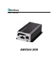
1) SD Card Slot: Slot to insert SD card. 2) IR Receiver: Receiver for IR remote control. 3) Alarm Input(2), Alarm Output(1) & RS232: Alarm Input (2) - Connect up to 2 alarm inputs, selectable between N.O./N.C. contacts. Alarm Output (1) - N.C or N.O type alarm out (form “C”). RS232 - Connect to RS232/RS485 compatible device. 4) Power LED: This LED ON indicates Power on. 5) Network Connector: RJ-45 network connection 10/100Mbps Ethernet.
○3 Video & Audio Input/Output: Video Inputs (2): Connect camera’s video output or other composite video source to the video input connection. Audio Input (1): Connect line level output of an audio preamplifier to the audio input connection corresponding to the appropriate camera. Video Output (1): Monitor for live and playback display and on-screen display. Audio Output (1): Connect to the line level input of an audio amplifier ○4 USB port: USB port recommended for connecting the USB mouse. 1.
1.6 FRONT & REAR PANEL CONNECTOR Alarm/RS232 GND ALARM_OUT GND ALARM_IN GND ALARM_COM RS232-RXD1 ALARM_IN_1 RS232-TXD1 GND AUDIO_IN GND AUDIO_OUT GND Audio/Video VIN1 GND VIN2 GND TV_OUT GND Power In ING_IN GND GND DC12V 1.7 INSTALLATION OF EMV200 Step 1. Please put your EMV200 on the suitable location of vehicle. Please see the figure below. Step 2. Please tighten 4 screws at 4 corners of device to the surface. Please see the figure below.
Now you have completed all mounting procedures. Possible Installation Locations Inside the Automobile Vehicle: Truck Glove box (inside or underneath) Drive seat (between seat and wall) or Passenger seat (underneath) (Users are suggested to use “support” for mounting option) Show the wiring on the wiring harness that connects to the electrical system.
Possible Installation Locations Inside the Automobile Vehicle Glove box (inside or underneath) Trunk (Users are suggested to use “suspend” for mounting option) Passenger seat (underneath) Drive seat (between seat and wall) Show the wiring on the wiring harness that connects to the electrical system.
Installing the Camera(s) and Monitor The DVR is typically connected to one camera installed inside the car. Other camera(s) can also be installed in different locations (for example, use the waterproof camera to the outside of vehicle). For installation procedure, please refer to the guide that came with the camera(s) you purchased. The Monitor power supply connects from the Automotive adapter (cigarette plug) Monitor and cameras must be purchased separately.
1.8 VIDEO INPUTS/OUTPUTS INSTALLATION Cameras and CCTV monitors must use copper center conductor/copper braid 75 Ohm video cable (e.g. RG-59, RG-6, RG-11) with BNC connectors. To avoid impedance mismatch and undesired loss/reflections, 50 Ohm coax cable (e.g. RG-58), or 75 ohm foil shield antenna cable and other types of coaxial cable are not compatible. All connected video sources must provide a 1 Vpp NTSC or PAL standard video signal.
1.10.1 Alarm Input Contacts This DVR provides one alarm input per camera. All inputs are programmable N.O. (Normal Open) or N.C. (Normal Closed) Inputs have to be switched by dry contacts. All settings are programmed in the ALARM menu (Section 0). Alarm input with N.O. (Normal Open) contact in idle state Alarm input with N.C. (Normal Closed) contact in idle state 1.10.2 Alarm Output Relay The relay output provides either Normally Open or Normally Closed dry contacts. Output relay in idle state 1.
1.12 NETWORK CONNECTION This section only describes physical connection to an Ethernet network. This step must be completed before the DVR can connect to the network. There are two basic types of connection: 1.12.1 Direct PC Connection through Crossover Network Cable The point-to-point connection of DVR and PC requires a crossover (crossed) network cable. This type of connection is ONLY used for direct connection to a single PC.
1.12.2 Network Connection through Patch Cable The connection to an existing network requires a normal patch cable (straight-through). The illustration shows the connection to a network switch or router. Figure 1-4 Network Connection through Patch Cable Pinout of straight patch cable 1.13 FINAL INSTALL PROCESS Once you have completed the basic wiring connections, you are ready to turn on the DVR. Simply plug in the power source. The POWER LED will light up if power is normal.
Chapter 2 2 MOUSE OPERATION EMV200 mobile DVRs support 2 sources to control the DVR. It can be controlled with a mouse and the handheld IR remote control. (For IR remote control, please refer to Appendix C Remote Control) This chapter will cover the basic operation using the mouse. 2.1 GENERAL USB MOUSE OPERATION 2.1.1 How to select a channel 1. In a view consisting of more than one channel, users can select a channel by clicking once on the desired channel screen.
3. Click the 2.1.3 button to go to live view. Field Input Options The following are examples of different types of fields available in the Configuration menu. Textbox: Click on the box and an on-screen keyboard will appear*. (see note about the on-screen keyboard below) Dropdown box: Click on the down arrow to see all selections, then directly click on an option to select it. Check box: Click on the box to enable it (checked) or disable it (unchecked). Button: Click the button to execute the function.
Chapter 3 3 CONFIGURATION This chapter provides information for configuring EMV200. 3.1 CONFIGURATION OF DVR EMV200 can be configured through On Screen Display Playback and Configuration Connect to the “Main Mon” output with a monitor and use the mouse or the remote control to configure menu settings. 3.2 LOGIN In order to access EMV200 options, users may be asked to log in for authority identification. To log in, follow these steps. 1. Right click on the screen to display the Main Menu 2.
Figure 3-2 On-screen Keyboard 3.3 On Screen Configuration Menu 1. To bring up the Main Menu, right-click with the USB mouse to bring up the root menu. Figure 3-3 On-screen Configuration 2. Left-click on the “Playback” icon “ below: Playback Bar ” to enter the Playback Menu. A Playback Bar appear as shown Name Description Layout TheEMV200 DVR has several display modes available.
Audio Press to cycle through Audio 1, 2,3,4 or no audio Fast Rewind Press to start fast reverse playback Play Press to playback ** Fast Forward Press to start fast forward playback Search Press to search by Time, Event or GPS. Please see “3.4 Search” for more details about search function. Archive Press to save a video clip to USB. Please see “3.5 Archive” for more details about archive function.
Play From: Select the time to begin the search by choosing the Date and Time. Click on the “Play” button to start the search. The DVR will automatically begin to play the video selected. The DVR will play the nearest time if there is no data at the selected time. In search playback mode, pressing the “Stop” button will return to the search menu. Record Time (Start): Displays the starting time of record data in the disk. Record Time (End): Displays the end time of record data in the disk.
Click button to start search action. Click button to enter GPS bordering search menu. Figure 3-7 Search Menu – GPS Bordering Search From: Select starting date and time To: Select ending date and time. GPS Border Type: Set GPS border type, select either circle or rectangle. Search Mode: Select if searching Inside or Outside the border. Center Lat.: Set the latitude if border type is circle. Center Lon.: Set the longitude if border type is circle.
3.4.3 Event Search Click button to enter Event search menu. Figure 3-8 Search Menu – Event Search From: Select starting date and time To: Select ending date and time. Select which event type(s) to search for. Choose from Alarm, Video Loss or Power On. Click on the Click on the button to select which cameras to include in the search. button to start searching. The search results will be shown as a list of events.
Play: Playback selected item Delete: Delete selected item Click button to return to the previous level of menu. Click button to enter GPS search menu. Click button to enter Time search menu. Click button to return to live view 3.5 ARCHIVE (USB) Right-click to bring up the Root menu, select Playback and click to enter Archive Menu. Figure 3-10 Archive Menu Camera: Select which cameras will be archived. Choose “Select All” to select all the cameras.
Chapter 4 4 DVR CONFIGURATION This chapter will walk you through the DVR Menu Settings step by step and show you how to set the DVR for your specific application. 4.1 Configuration Menu 1. To bring up the Main Menu, right-click with the USB mouse to bring up the root menu. Figure 4-1 Root Menu 2. Left-click on the “Configuration” icon “ Section 3.2 LOGIN above). ” to enter the Configuration Menu.
4.2 CAMERA SETTING Figure 4-3 is a screenshot of the CAMERA SETTING MENU. This menu is used to configure individual camera settings. Figure 4-3 Camera Settings-Normal 4.2.1 Normal No.: Camera number. Speed: Frame rate in frames (images) per second (FPS) for continuous recording. The speed is limited by the maximum total recording capacity of the DVR as allocated across all the installed cameras, with an upper limit of 30 FPS (NTSC – 25 PAL) per individual camera (real time recording).
Click Click 4.2.2 button to enter Alarm menu. button to return to the previous level of menu. Video Adjust Figure 4-5 Camera Settings-Video Loss Camera: Select the camera you wish to adjust. “Title” will change to the name of the selected camera. Brightness: Adjusts how bright/dark the picture appears. If details appear to be lost in the shadows or darker regions, try increasing the Brightness.
4.2.3 Alarm Figure 4-6 Camera Settings-Alarm Speed: Maximum desired frame rate in frames per second (FPS) for event recording; if more than one camera requires simultaneous event recording, the total for all cameras cannot exceed the maximum available FPS for the DVR at the corresponding resolution setting, and the available FPS may be divided across the cameras responding to an event.
Figure 4-7 Record Settings 4.3.1 Record Record Overwrite: Check the box and the disk will begin overwriting when full. NOTE: Unless this box is checked, THE DVR MUST STOP RECORDING WHEN THE DISK IS FULL. The use of record overwrite is strongly recommended. If you do not use this feature, please be sure to make specific arrangements to monitor/be notified when the disk is full. Power Delay-On: Set the delay time to supply power to the DVR in order to avoid excess consumption at ignition.
4.4 ALARM/GPS Figure 4- is a screenshot of the ALARM/GPS SETTING MENU. This menu will guide you through alarm and GPS setup. Figure 4-8 Alarm/GPS - Alarm 4.4.1 Alarm-Alarm Settings Figure 4-9 Alarm – Alarm Settings Alarm: Select the alarm input trigger connection number from 1 to 2. Enable: Check box to enable response to that alarm trigger. Input Type: This field is to change the type of alarm trigger.
N.O.: Normal Open contact. N.C.: Normal Closed contact. Display Switch: Select which channel to be displayed when alarm is triggered. Available options are CH1 and CH2. Alarm Output: This will transmit a signal through the alarm output. It can be set to either “NONE” (not active) or “1” (selects alarm relay to be active). Output Type: Output action when alarm is triggered. Timeout: Alarm output lasts for the set time duration.
4.4.2 Alarm-Event Settings This section covers notifications due to internal system event warnings. Figure 4-10 Alarm – Event Settings Event: Select from the following event types. SD Card Full: If SD card capacity is full, DVR will create a SD Card Full Event. SD Card Missing: If SD card is missing, DVR will create a SD Card Missing Event. Power Loss: If power is disconnected, an alarm event will be triggered when power is restored.
Email Notify: Check box to enable email notification when SD card is full. Email operation requires that valid email settings have been entered in the Network Setting/Email setup screen. Network Alarm: Check box to send out a network alarm to client PC. (requires PowerCon software and setting up Alarm Server in Network Setup menu) Alarm Output: This will transmit a signal through the alarm output. It can be set to either “NONE” (not active) or “1” (active).
Output Type: Timeout: Alarm output lasts for the set time duration. Permanent: Alarm will be continuously active until user presses the “Enter” key or resets the alarm remotely. Transparent: Alarm output remains active until event ends. Trans+Timeout: Alarm output continues until event ends, then continues for the set time duration. Timeout Duration: Time duration selectable from 1 to 150 seconds. Click button to return to the previous level of menu.
Network Loss: Figure 4-17 Alarm – Event – Network Loss Alarm Output: This will transmit a signal through the alarm output relay. It can be set to either “NONE” (not active) or “1” (active). Output Type: Output action when alarm is triggered. Timeout: Alarm output lasts for the set time duration. Permanent: Alarm will be continuously active until user presses “Enter” key. Transparent: Alarm output remains active until event ends.
GPS Loss: Figure 4-18 Alarm – Event – GPS Loss Email Notify: Check box to enable email notification when GPS is lost. Email operation requires that valid email settings have been entered in the Network Setting/Email setup screen. Network Alarm: Check box to send out a network alarm to client PC. (requires PowerCon software and setting up Alarm Server in Network Setup menu) Alarm Output: This will transmit a signal through the alarm output relay. It can be set to either “NONE” (not active) or “1” (active).
4.4.3 Alarm – Video Loss Figure 4-19 Alarm – Video Loss Camera: Select the camera you wish to configure, “Title” will change to the title name of the selected camera. Enable: Check box to enable Video Loss detection. Alarm Output: This will transmit a signal through the alarm output relay. It can be set to either “NONE” (not active) or “1” (active). Output Type: Output action when alarm is triggered. Timeout: Alarm output lasts for a set time duration.
Click button to return to the previous level of menu. 4.4.4 Alarm-GPS Speed Figure 4-21 Alarm – GPS Speed Speed Unit: If the speed is being recorded from the GPS receiver, the desired speed display units must be selected. Select GPS speed unit from KPH and MPH. Selecting MPH converts the GPS signal to display speed in miles per hour. GPS Speed: Select whether to record the vehicle speed or not. Speed Higher Limit: Set the speed to determine at which level the alarm will be triggered.
4.4.5 Alarm-GPS Event Action Press to enter GPS Event Action Menu. Figure 4-22 Alarm – GPS Event Action Alarm Output: This will transmit a signal through the alarm output relay. It can be set to either “NONE” (not active), “1” (active) or “2” (active). Output Type: Output action when alarm is triggered. Timeout: Alarm output lasts for the set time duration. Permanent: Alarm will be continuously active until user presses “Enter” key. Transparent: Alarm output remains active until event ends.
4.4.6 Alarm-GPS Fencing Press to enter GPS Fencing Menu. Figure 4-23 Alarm – GPS Fencing GPS Alarm: Select “On” to enable GPS alarm. Select “Off” to disable GPS alarm function. GPS Border Type: Set to a circle or rectangle and dynamic prompts for Latitude and Longitude appear. Center Latitude: Set the latitude if border type is circle. Center Longitude: Set the latitude if border type is circle. Radius: If GPS border type is circle, this option defines radius. Select radius unit from Km and Mi.
4.5 Date/Time Setting Figure 4-24 is a screenshot of the DATE/TIME SETTING MENU. This menu is for setting up the date/time parameters for the DVR. Figure 4-24 Date/Time Settings 4.5.1 Date/Time Settings Time Zone: Set the time zone that the DVR adjusts to when updating from the time server. Date: Set current Date. Time: Set current Time. Date Format: Choose date format from yyyy/mm/dd, dd/mm/yyyy, and mm/dd/yyyy. Time Format: Change time format between 12H and 24H mode.
Click 4.5.2 button to return to the previous level of menu. Daylight Saving Click button to set up daylight saving parameters Figure 4-25 Date/Time Settings-Daylight Saving Daylight Saving: Check the box to enable automatic daylight saving time adjustment. Start Date: Set the start date for daylight saving time. Start Time (hh:mm): Set the time when daylight saving time begins. Set To (hh:mm): This is what the time will change to when daylight saving begins.
Figure 4-26 Display Settings 4.6.1 Title Vehicle ID: Input the vehicle ID by using the on-screen keyboard. Maximum text length is 16 characters. Camera 1~2: Input camera name for camera 1~2 by using the on-screen keyboard. Maximum text length is 16 characters. 4.6.2 Monitor On Screen Display Click button to set up OSD parameters. Figure 4-27 Display-OSD Main Monitor Main Title: Check the box to display main title.
Camera Title: Check the box to display camera titles for main monitor. Date/Time: Check the box to display current date/time. Playback Date/Time: Check the box to display playback date/time. Playback Status: Check the box to display playback status. Event Status: Check the box to display event status. SD Card Status: Check the box to display SD card status. GPS Status: Check the box to display GPS status. Network Loss: Select Disabled, LAN and 3G. 4.6.3 Layout Click button to set up Layout parameters.
4.6.4 Sequence Click button to set up Sequence parameters. Figure 4-29 Display-Sequence Step: Sequence order. For reference. Camera: Select which camera appears in the current step. Dwell (sec): Set the dwell time for each step. Sequence dwell time can be set from 0 to 99 seconds. Sequence repeats continuously from steps 1 through 20 until interrupted. Click button to return to the previous level of menu. 4.7 NETWORK SETTING Figure 4-30 is a screenshot of the NETWORK SETTING MENU.
Figure 4-30 Network Menu 4.7.1 LAN Settings Figure 4-31 Network Menu – LAN Network Type: Static IP: User can set a fixed IP for network connection. DHCP: DHCP server in LAN will automatically an assign IP configuration for the network connection IP address: This field shows the DVR’s current IP Address. A static IP address must be set manually. If DHCP or PPPoE is selected, this value will be assigned automatically.
DNS Server 1: This field shows the primary DNS server for your network. If DHCP is selected and an internet connection is available, this value should be assigned automatically. This field must have a valid DNS address in order to use the DDNS feature (see Sections 4.7.5 and 7 DDNS for more detail). DNS Server 2: This field shows the secondary DNS server for your network. HTTP Port: Port number for HTTP/WEB communication. Additional information: 1.
• Dynamic and/or Private Ports 49152 thru 65535 So, rather than encounter a port conflict by choosing a port commonly used for another purpose (like port 25 for SMTP mail or port 448 for secure sockets), choose an ‘unusual’ port number. For example, add 50,000 to your house number: 50,123 is less likely to lead to a port conflict. For a list of the known and registered ports, see http://www.iana.org/assignments/port-numbers Bandwidth (Kbps): Specify, disabled / 128 K/ 256 K / 512 K / 768K/ 1M / 3M bps.
DNS Server 1: The primary DNS server provided by ISP will be displayed. DNS Server 2: The secondary DNS server provided by ISP will be displayed. Click button to stop mobile connection. Click button to start mobile connection. Click button to return to the previous level of menu. 4.7.3 Email Settings Figure 4-33 Network Menu – Email Settings SMTP Server: Assign the SMTP (e-mail) server’s name. NOTE: For more reliable email service, use the server’s IP address.
4.7.4 DDNS Settings DDNS Server: Select either “EverfocusDDNS” or “www.dyndns.org” as the DDNS provider. If DDNS will not be used, simply select “Disable”. EverfocusDDNS Figure 4-34 Network Menu – DDNS Settings DVR Name: Input the desired name for the DVR Register/Update: Click the button to submit and register the name to the Everfocus server. The DDNS name you choose must be unique; that is, it must not already be in use. Please go to the website http://everfocusddns.
Figure 4-35 Network Menu – DDNS- www.dyndns.org Host name: Host name created through the dyndns account. User name: User name of the dyndns account. Password: Password of the dyndns account. Note: For more details on DDNS setup, please see “Chapter 7 - Everfocus DDNS Setup”. Click 4.7.5 button to return to the previous level of menu.
This menu defines the parameters for communicating with a PC. Server IP1~3: IP address of client PC. The network alarm can be transmitted to up to 3 addresses. Protocol: Select the protocol type for alarm transmission: UDP: User Datagram Protocol TCP: Transmission Control Protocol Port: Select the transmission port for network alarm messages Network ID: The network ID is an identifier for the alarm transmitter (DVR sending the alarm). Click 4.7.6 button to return to the previous level of menu.
Click Click button to test connection. button to return to the previous level of menu. 4.7.7 Network Test Figure 4-38 Network Menu – Network Test Test Server Address: Enter the server address to be tested. Click button to start testing the network connection. 4.7.8 Remote/Mobile Figure 4-39 Network Menu – Remote/Mobile Check the box H.264: For MobileFocus* software (iPhone/ Android edition).
Check the box Mjpeg: For MobileFocus* software (iPhone/Android/BlackBerry edition) and mobile web page (IP Cameras from iPhone/Android/Blackberry and Nokia) by http browser. The "MobileFocus” by EverFocus allows you to connect to your EverFocus DVRs and IP Cameras from your smart phone. With MobileFocus, you can view video streams and control the PTZ cameras easily. * 4.8 SYSTEM 4-39 is a screenshot of the SYSTEM MENU. This menu is for setting up the general system parameters for the DVR.
Add Click “Add” button to add a new user. Set the name (case-sensitive), password, access level and status. Press “Add” button to confirm a new user or “Cancel” to exit without making changes. Figure 4-40 System-User-Add Edit Click “Edit” button to make changes to an existing user account. Press “Save” button to save changes or “Cancel” to exit without making changes. Figure 4-41 System-User-Edit There are three system access levels. The following charts show the rights of each level.
Local Local Admin User Guest Live View Copy Playback O O O O O O O O O O O O O O O O X O X X X O O O X X X X X X X X O Admin User Guest O O O O O O O O O O O O O O O O X O X X X O O O X X X X X X X X O Configuration Camera Record Alarm/GPS Date/Time Display Network System Information Web Web Live View Copy Search & Playback Camera Record Alarm/GPS Date/Time Display Network System Information 1. Only USER submenu; only access to change own password, and to access operator ID’s 2.
4.8.2 I/O Control Figure 4-43 is a screenshot of the I/O Control Setting Menu. This menu is used to define the settings for controlling the DVR through RS485, and for DVR control of attached PTZ cameras. Figure 4-42 System-I/O Control-RS232 RS232 Baud Rate: This field is to set the speed at which is used to transmit instruction or information through the RS232 port on the DVR. There are eight different speeds: 1200 BPS, 2400 BPS, 4800 BPS, 9600 BPS, 19200 BPS, 38400 BPS, 57600 BPS and 115200 BPS.
4.8.3 DISK Info Figure 4-44 is a screenshot of the SD CARD MENU. This menu is used to review the SD card’s settings and status. No values in this screen can be changed by the operator. Figure 4-43 System-Disk Record Time (Start): Shows earliest recorded time on the DVR. Record Time (End): Shows latest or most current recorded time on the DVR. SD Card Info Health Status: Displays current status. Card Size/Total: Shows total SD card size. Card Size/Usage: Shows percentage of used SD card space.
4.8.4 LOG Figure 4-46 System-Log This screen is used to choose, display and/or export log entries. From Date: Select starting date of log to be displayed. Time: Select starting time of log to be displayed. To Date: Select end date of log to be displayed. Time: Select end time of log to be displayed. Log Type: Configurations: to see log entries related to configuration changes. Event: to see log entries related to events. Record: to see log entries related to recording changes.
Export Log to USB: Press button to export log data to USB. Figure 4-47 Log List Prev Page: Go to the previous page of log. Next Page: Go to the next page of log. Close: Close the window Click button to return to the previous level of menu. 4.8.
Audio Output Channel: Select audio output channel. Language: Choose which language the DVR uses. The available languages may vary based on region. User Login: Check this box to require user login for menu access from the front panel. When this is disabled, no username or password is required to access the system from the front panel, and all users operate with ADMIN rights from the front panel. Auto Logoff: Check this box to automatically logoff the current front panel user after 3 minutes of inactivity.
4.9 INFORMATION Figure 4.50 is a screenshot of the INFORMATION MENU. This menu displays important (read only) system information. Figure 4-50 Information System Version: Displays firmware version number. Model: Displays DVR model number. NTSC/PAL: Displays current video format selected based video format on Camera 1 input at boot up. Status Disk: Displays status of the installed disk(s); normal disk operation is indicated by “OK”. Fans: Displays fan status; normal fan operation is indicated by “OK”.
Chapter 5 5 Networking Overview This chapter will give you a basic instruction on how to set up the DVR for network connection. It is highly recommended that you have a working knowledge of what a network is and how it works. This will be helpful in completing the networking process. 5.1 Introduction to TCP/IP TCP/IP is the group of protocols used by the Internet and most Local Area Networks (LANs) throughout the world.
5.4 Virtual Ports A port number represents a "channel" or entryway for network communications. Port numbers allow different computers to utilize network resources without interfering with each other. Port numbers most commonly appear in network programming, particularly socket programming. Sometimes, though, port numbers are made visible to the casual user. For example, some websites on the Internet use a URL like the following: http://www.sitename.
Do you have a static IP address? ______________ A Static IP address means you use the same IP address every time you connect to the Internet. With a static IP address, other Internet users always know the address of your location and can easily connect with it. This makes it much simpler to host a website, email server, or other type of server connection. Everfocus suggests using a static IP address. If this is not available, you will need to use a dynamic IP address. This is explained below.
5.7 Simple One to One Connection Crossover Ethernet Cable Pin outs: The Figure below shows the pin configurations for a cross-over cable. Connection Procedure: The First step is to purchase or make a cross-over cable. We recommend purchasing one if you have never made a cross-over cable.
The next step is to set the computer’s network settings to match those of the DVR. You will need Administrator privileges on your Windows machine to do this. To assign a fixed IP address in Windows 2000/XP.
Click on the option that says “Use the following IP address” Assign an IP address of 192.168.1.2, a Subnet Mask of 255.255.255.0, and a Default Gateway of 192.168.1.1, then click OK. Restart both the computer and the DVR. To access the DVR from the computer, simply open Internet Explorer and in the address bar type: http://192.168.1.
5.8 Direct High Speed Modem Connection Straight Through Ethernet Cable Pin outs: The Figure below shows the pin configurations for a straight cable. Connection Procedure: The first step is to purchase or make a straight through cable. We recommend purchasing one if you have never made a straight through cable.
Note: If you have a dynamic IP address, you can set the DVR to DHCP to automatically detect the network settings. Therefore, it can use a dynamic IP address. Exit from the DVR’s Menu to save the settings. To access the DVR from a computer, open Internet Explorer and in the address bar type: http:// (IP address given by your internet service provider) Note: When using this type of connection, only one device can be connected to the modem at a time.
Connection Procedure: The First step is to purchase or make a straight through cable. We recommend purchasing one if you have never made a straight through cable. Please remember you can not use a cross-over network cable for this application Once you have a straight through cable plug one end into the LAN port on the back of the recorder and the other into the router. Log into the EverFocus DVR menu and go to the Network Setting Menu.
Take the values for Subnet Mask and Default Gateway and input them into the DVR; these values should be exactly the same in both devices. However, you should change the last number of the IP address. For example, if the IP address of the computer is 192.168.2.101, the DVR’s IP address should be 192.168.002.050.
Chapter 6 6 REMOTE OPERATION FROM BROWSER 6.1 CONNECTING TO EMV200 To access the DVR from a computer, open an Internet Explorer window and in the address bar type: Local connection: http:// (IP address from the DVR’s Network Menu): IP port used e.g. http://192.168.1.163:2468 Internet connection: http:// (IP address given by your Internet Service Provider): IP port used e.g. http://57.182.67.204:2468 You should then see a login prompt.
6.2 BROWSER SECURITY SETTING 6.2.1 Installing ActiveX controls When you first connect to the DVR’s IP address, you should see a screen like the one below. If you do not see a yellow bar like the one the arrow is pointing at, your security settings may be too high. If so, go to “Section 6.2.2 Enabling ActiveX Controls.” Right click on the yellow bar and select “Install This Add-on…” Install the ePlusDVR.cab file when prompted to do so.
Once the file finishes installing, you will return to the screen like the one below. Right click on the yellow bar and select “Run Add-on…” Install the MSXML file when prompted to do so.
Now, you will be able to see the remote live page. 6.2.2 Enabling ActiveX Controls Note: This section is only necessary if you DO NOT see the yellow ActiveX bar at the top of your browser screen when you first connect to the DVR. At the top of the Internet Explorer Window, click on Tools, then select Internet Options. Click the Security tab at the top of the window, then choose Custom Level near the bottom.
In the Security Settings window, scroll to “ActiveX controls and plug-ins” 75
Set the controls as follows: “Enable”: Allow previously unused ActiveX controls to run without prompt (Internet Explorer 7 only) Allow scriptlets (IE7 only) Automatic prompting for ActiveX controls Binary and script behaviors Display video and animation on a webpage that does not use external media player (IE7 only) Run ActiveX controls and plug-ins Script ActiveX controls marked safe for scripting “Prompt”: Download signed ActiveX controls Download unsigned ActiveX controls “Disable”: I
6.3 REMOTE LIVE VIEW 4 1 2 5 3 1. Click on a camera number on the left side of the display to switch that camera to full screen. Click on “4UP” to display 4 screens. 2. You can click the “Mic” button to transfer audio to DVR from client side if there is a microphone attached to the PC and an amplifier and speaker attached to the DVR.
3. The status of each camera is represented by different colors on the left side of the screen. Green means normal; orange indicates a Motion alarm; blue indicates Video Loss, red indicates an alarm event and grey means disable 4. Menu bar: Menu buttons for setup, search and export, details are explained in following chapters. Live View Camera Setup Record & Play Setup Alarm/Event Setup Date/Time Setup Display Setup Network Setup System Setup Information Setup Copy Menu Search Menu 5.
6.4 REMOTE PLAYBACK To playback the video, click the “Search” button. Select from “Time Search”, “GPS Search” or “Event Search”. For more details about Search setting, please refer to “3.4 Search Setting”. Playback Control Keys Back: returns to live view Playback Control Keys: 1. Fast rewind the video. 2. Play Reverse the video. 3. Stop playback. 4. Pause 5. Playback the video. 6. Fast forward the video.
Chapter 7 7 EVERFOCUS DDNS SETUP Setup Steps: Step 1. Set up the Network Menu according to the instructions detailed in the Networking chapter. (Make sure that DNS Server 1 is set correctly or DDNS will not work) Step 2. Go to the website http://everfocusddns.com and check for an available name. Note: This step is optional, though recommended, as it is used to check the availability of a host name. If the name is already used, and attempt to register that name must fail.
Chapter 8 8 LINKSYS & D-LINK PORT FORWARDING 8.1 TYPICAL LINKSYS PORT FORWARDING This section will cover a few simple configurations for the Linksys router. This chapter is only to offer some help to the installer and end user. Please understand we DO NOT support this product and will not give tech support on it. If you need additional technical support on this router you must call Linksys. To access the Web-based Utility, launch a web browser and type the Router’s IP address, typically 192.168.1.
Applications and Gaming allows you to set up public services on your network, such as web servers, ftp servers, e-mail servers, or other specialized Internet applications. (Some Internet applications may not require any forwarding) To forward a port, enter the information on each line for the criteria required. Descriptions of each criterion are described here. Application - In this field, enter the name you wish to give the application.
8.2 TYPICAL D-LINK PORT FORWARDING This section will cover a few simple configurations for the D-Link router. This chapter is only to offer some help to the installer and end user. Please understand we DO NOT support this product and will not give tech support on it. If you need additional technical support on this router you must call D-Link. Whenever you want to configure your network or the DI-624, you can access the Configuration Menu by opening a web-browser and typing in the IP Address of the DI-264.
Click Virtual Servers on the left to bring up the following screen. Virtual Servers allows users who are connecting remotely to access services on the router’s Local Network. The functions of each field are described below. Virtual Server - Select Enabled or Disabled Name - Enter the name referencing the virtual service Private IP - The IP address of the device running the local services. Protocol Type - The protocol used for the virtual service.
Chapter 9 9 SD CARD READER Whenever a SD card is inserted into EMV200, an EMVPlayer will be installed to the SD card automatically. Use this EMVPlayer to read the video file recorded in the SD card. 9.1 Understand User Interfaces Insert the SD card to PC and run to execute EMVPlayer.
9.2 Basic Operations 9.2.1 Open File Press “Load” button and select “OpenFile”, browse file location and select the file (.avr) already archived in your PC. 9.2.2 Open SD Press “Load” button and select “SDCard”, EMVPlayer will read the file recorded in the SD card. 9.2.3 Playback Controls Click on Playback Control Buttons to Playback, Pause, fast reverse, play reverse, play forward or fast forward. Fast reverse Play reverse Pause Play forward Fast forward 9.3 Search Video 9.3.1 Search by Date/Time 1.
9.3.3 Search by Video Slide Bar 1. Grab Video Slide Bar cursor to move to desired position. Start time End time 2. Click to magnify the time frame. Click time frame to 5 min, 1hr and 12hr. to reduce the time frame. Every click changes the 9.4 Archive and Snapshot 9.4.1 Archive Video from Video Window EMVPlayer can archive video into AVR file. However, archive functions are not designed to save long time video. Archive to AVR file should always be limited to the minimum time range. 1.
Chapter 10 10 TROUBLESHOOTING If you have problems with the system, run through the following checklist to see if you can solve the problem. The DVR will not go into record mode. Bring up the DVR’s Menu and check under the Camera Menu. Verify that all connected cameras are checked as “Installed” and that Record Mode is set to “Continuous”. Check the Disk or Information Menus and verify that the internal hard drive is being detected. The DVR displays nothing on the main monitor.
Appendix A APPENDIX A: TIMING OF ALARM MODES Transparent Mode Input Event Alarm Duration t t Event = t Reaction t Event: t reaction: Duration of alarm input source (motion, contact, system events...) Resulting duration for this alarm mode, related to event record, alarm outputs, OSD message, buzzer Timeout + Transparent Mode Input Event Alarm Duration t Event t Duration t t Reaction t Event: t Duration: t reaction: Duration of alarm input source (motion, contact, system events...
Timeout Mode Input Event Alarm Duration t t Event t Duration = t Reaction t Event: t Duration: t reaction: Duration of alarm input source (motion, contact, system events...
Timeout Mode: Retrigger of Alarms t Event: t Duration: t reaction: Duration of alarm input source (motion, contact, system events...) Alarm duration for timeout, defined in the event setup menus Resulting duration for this alarm mode, related to event record, alarm outputs, OSD message, buzzer Timeout+Transparent Mode: Retrigger of Alarms t Event: Duration of alarm input source (motion, contact, system events...
Appendix B APPENDIX B: EXPRESS SETUP RECORDING VALUE SELECTION RULES Case 1: Record Mode: Normal + Event Record With: Recording days The DVR will Auto adjust image Quality and Event frame rate to match the number of Recording days which user selected: According to resolution, event hours and other assumptions above, the DVR will attempt to select one set of suitable quality and event frame rate by checking if set 1 meets the requirements, and proceed in order unit the requirements are met.
Case 3: Record Mode: Normal + Event or Event Only Record With: Preset Setting DVR will apply the settings in the table below to all cameras according to the Preset Settings.
Appendix C APPENDIX C: REMOTE CONTROL The IR remote control is an accessory to enhance the convenient operation of the DVR. You can perform all the settings and operations from the remote control. The effective distance is up to 33 feet line of sight. The keypad functions are same as the front panel buttons of the DVR. ID number here must correspond to the “IR Remote ID” in “I/O Control Setup Menu”. Used to select a DVR when there is more than one unit.
EverFocus Electronics Corp. EverFocus Taiwan: 12F, No.79, Sec. 1, Shin-Tai Wu Road, Hsi-Chih, Taipei, Taiwan TEL: +886 2 2698 2334 FAX: +886 2 2698 2380 www.everfocus.com.tw marketing@everfocus.com.tw EverFocus Europe - Germany: Albert-Einstein-Strasse 1, D-46446 Emmerich, Germany TEL: +49 2822 93940 FAX: +49 2822 939495 www.everfocus.de info@everfocus.