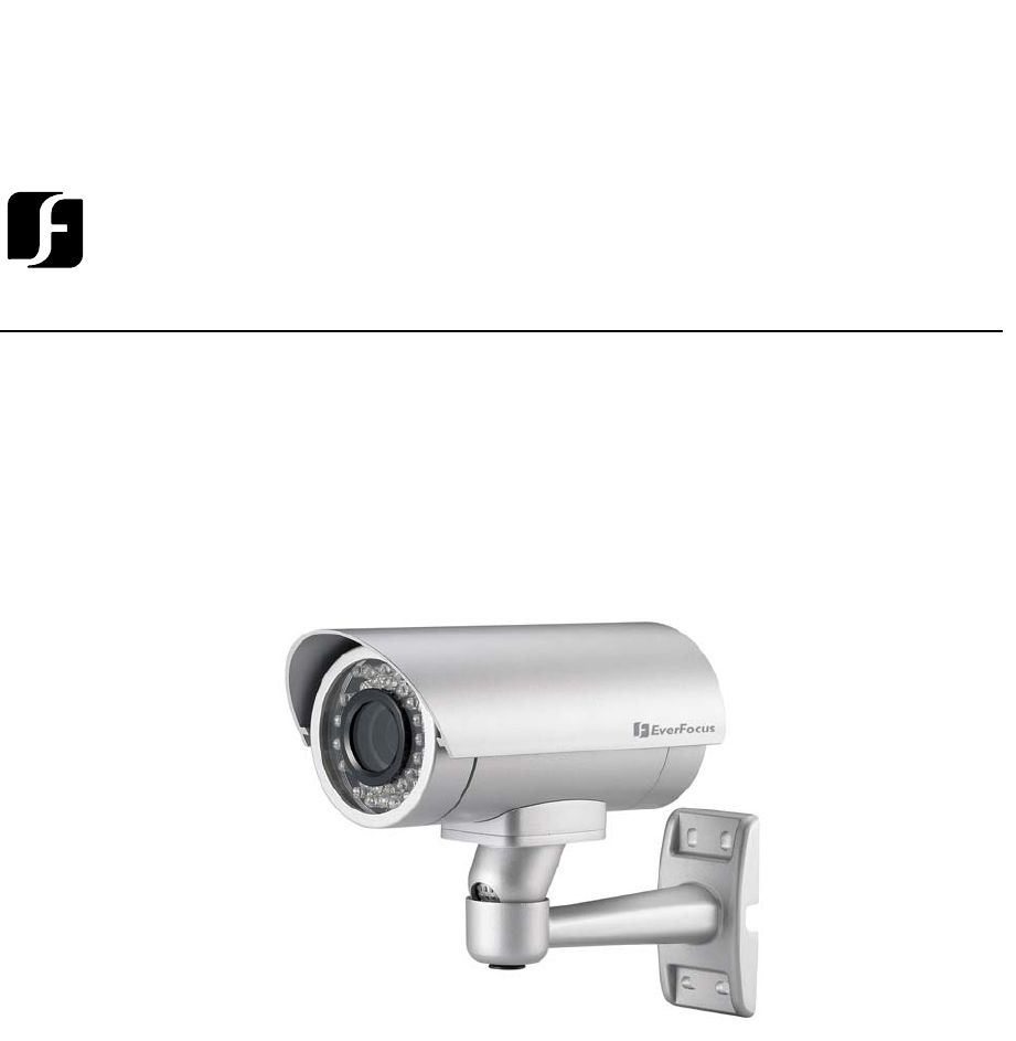
Volume 1 EverFocus Operation Instruction 1/3” CCD Outdoor IR Bullet Color Camera, with Vari-focal EZ430
Operation Instruction 2008 EverFocus Electronics Corp Please read this manual first for correct installation and operation. This manual should be retained for future reference. The information in this manual was current when published. The manufacturer reserves the right to revise and improve its products. All specifications are therefore subject to change without notice. All rights reserved.
Federal Communication Commission Interference Statement This equipment has been tested and found to comply with the limits for a Class A digital device, pursuant to Part 15 of the FCC Rules. These limits are designed to provide reasonable protection against harmful interference in a residential installation. This equipment generates, uses and can radiate radio frequency energy and, if not installed and used in accordance with the instructions, may cause harmful interference to radio communications.
Table of Contents 1. Product Overview…………………………………………………….…5 1.1 Features ............................................................................ 5 1.2 Accessory Parts List......................................................... 6 1.3 Specifications ................................................................... 7 1.4 Dimensions........................................................................ 8 1.5 Camera Component Description..................................... 10 1.6 Back Panel Layout ..
C H A P T E R 2 I N S T A L L A T I O N C H A P T E R 1 P R O D U C T O V E R V I E W Chapter 1 Product Overview The EverFocus EZ430 is a true day/night weatherproof IR bullet style color camera. Engineered with a motorized lens controller, you can adjust the zoom, focus and IRIS level with a simple touch of a button located on the back panel of the camera housing.
C H A P T E R C H A P T E R 2 1 I N S T A L L A T I O N P R O D U C T O V E R V I E W 1.2 Accessory Parts List Please be careful when you unpack the box due to the electronics devices inside.
CCHHAAPPTTEERR 21 IPNRSOT DA UL C LT A TOI V OE NR V I E W 1.3 Specifications Items Parameter Pickup Device 1/3” SONY Super HAD CCD Video Format NTSC or PAL Scanning System NTSC:525 TV lines, 60 fields/sec PAL:625 TV lines, 50 fields/sec. Picture Elements 768 x 494(NTSC); 752 x 582 (PAL) Horizontal Resolution 520 TV lines Sensitivity 0.4 Lux / F=1.2(IR OFF) ; 0 Lux (IR ON) S/N Ratio Over 48 dB(AGC Off ) Electronic Shutter 1/50(1/60)~1/100,000 Lens Type Vair-focal lens, f=2.
C CH HA AP PT TE ER R 2 1 IPNR SOTDAULCLTA TOI VOENR V I E W 1.4 Dimensions Radius: 88mm/3.
C H A P T E R 2 I N S T A L L A T I O N C H A P T E R 1 P R O D U C T O V E R V I E W Dimension of whole camera with bracket 9
C H A P T E R 1 P R O D U C T O V E R V I E W C H A P T E R 2 I N S T A L L A T I O N 1.
C H A P T E R 1 P R O D U C T O V E R V I E W C H A P T E R 2 I N S T A L L A T I O N 1.6 Back Panel Layout UP Left Right Control Mode Down There are two modes in “Control Mode” button. When power is on, it turns to green light. Press “Control Mode” can toggle switch green light and red light. 1. Green Light on Press Up and Down keys to adjust Zoom In / Zoom out Press Right and Left keys to adjust focus 2. Red Light (1) Press Up and Down keys to adjust IRIS Level.
C H A P T E R 2 I N S T A L L A T I O N Chapter 2 Installation This chapter will describe, in general terms, how to install the EZ430 camera. STEPS: 1. Wire and mount the camera, See 2.1 2. Adjust the camera position, See 2.2 3. Adjusting image, See 2.3 Warning To prevent electrical shock, turn off the electrical power before making electrical connections. Do not connect high voltage power to the camera. It may damage the camera.
C H A P T E R 2 I N S T A L L A T I O N 2. Fix the camera to the wall by using the 4 screws. 2.2 Adjusting Camera Position Adjust camera for the best viewing angle by using hex key wrench. Adjustment Horizontally Note: Before you adjust camera’s angle, please use Hex key Wrench to loose the screw first. To adjust the angle easier and to avoid paint-off scratches the bracket.
C H A P T E R 2 I N S T A L L A T I O N 2.3 Adjusting Image 1. There is a protect cover at camera’s back panel, loose screw A. Screw A Screw B 2. Remove the “protect cover”.
C H A P T E R 2 I N S T A L L A T I O N 3. Adjust focus, zoom and IRIS level. Control Mode Adjust Zoom and IRIS level Adjust Focus (1)Green Light on Press Up and Down keys to adjust Zoom In / Zoom out Press Right and Left keys to adjust focus (2)Red Light (A) Press Up and Down keys to adjust IRIS Level. (B) Press left and right keys simultaneously to reset the default value for IRIS level. 4.
C H A P T E R 2 I N S T A L L A T I O N Headquarter Office Beijing office 12F, No.79 Sec.1 Shin-Tai Wu Road, Hsi-Chi, Taipei, Taiwan Tel: +886-2-26982334 Fax: +886-2-26982380 Room 609,Technology Trade Building.