Volume 1 EverAccess User’s Manual FLEX Series Access Control Management Software Flex1.
EVERFOCUS ELECTRONICS CORPORATION Flex1.0 Instruction Guide © 2004 Everfocus Electronics Corp 1801 Highland Ave Duarte CA 91010 Phone 626.844.8888 • Fax 626.844.8838 All rights reserved. No part of the contents of this manual may be reproduced or transmitted in any form or by any means without written permission of the Everfocus Electronics Corporation.
Table of Contents CHAPTER 1 Introduction ....................................................................................................................................... 1 About This Guide............................................................................................................................... 1 How to Use This Guide?............................................................................................................ 1 About the software ...................................
Change the Serial Port for a Controller ................................................................................. 19 Configure Doors ....................................................................................................................... 20 Edit Door Location Information .............................................................................................. 20 Set Door Open Time ....................................................................................................
Select a Controller................................................................................................................... 43 Select an Access group .......................................................................................................... 43 Set Access to Doors ................................................................................................................ 43 Set Access Authority.....................................................................................
Edit Cardholders’ Profiles ....................................................................................................... 66 Select Cardholder’s Photo ...................................................................................................... 67 Filter Cardholders............................................................................................................................ 68 Edit Card Access Attributes.........................................................................
Event Warning Message ............................................................................................................... 101 CHAPTER 12 Device Control ............................................................................................................................... 104 Resources List............................................................................................................................... 104 Remote Arm/Disarm: ..................................................
Chapter 1 Introduction This chapter describes the content of this user manual, and explains the fundamental functionalities and the basic operations of the software. This chapter will present: • Basic information about this user’s manual • A basic introduction to the software • A basic introduction to the steps to setup the access control system.
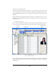
About the software EverAccess Flex Series Software is designed to work with the EverAccess Flex series access control hardware. The software provides a simple yet powerful interface to allow system administrators and other users to manage the EverAccess system with ease and flexibility. The fundamental goal of EverAccess Flex software is to provide ease-of-use, so it is designed in a very straightforward, simple-to-understand manner. The program layout is described below. Program Layout Fig. 1.
Fig. 1.2 Menu Items Under “Management” The next section introduces how to start EverAccess Flex software. How to Start To start EverAccess Flex software on your computer, follow the steps below: 1. After the installation is complete, go to the “Start” menu Æ “All Programs” Æ “EverAccess Flex Series Access Control System”. Click “EverAccess Flex Software”. 2. A system login dialog box will appear after the initialization flash screen, to prompt users to enter a name and password, shown as Fig. 1.3: Fig.
• Free hard drive space: 100M bytes free space • Screen resolution: 1024x768 • An available serial port (in the event that the computer does not have a serial port, a third party USB-to-Serial converter cable may be used.) • An available USB port (1.1 or above) Basic Steps to Setup the System In this section, the basic steps to setup the system will be addressed. The related chapter in which detailed descriptions are outlined is given for reference.
Chapter 2 Installation The following chapter describes the installation procedure. The main objective of this chapter is to explain: • How to install the software Installation process Insert the software CD into the management PC’s CDROM drive. On the PC, double click on “My Computer”, and then on the appropriate drive for the CDROM. Now double click “Setup.exe” in the software CD, and the following display should appear: Fig. 2.
Fig. 2.2 If you wish to change the destination folder click “Browse” in this dialog. To continue with the installation click “Next”. This will take you to the next step of the installation as shown in the following figure: Fig. 2.3 The program folder can be changed in this dialog box. For typical installations, use the default program folder (EverAccessFlex). Click “Next” to continue the installation. Fig. 1.4 and Fig 1.5 show the dialog boxes indicating that the installation is complete.
Fig. 2.4 Fig. 2.5 Click “Finish” to complete the installation.
Uninstall the program To uninstall the program, go to “Control panel” in Windows. Select “Add or Remove Programs”, then choose “EverAccess Flex Software”. Click “Remove”, and the following dialog box will appear. Fig. 2.6 Select “Remove” and click “Next”. The software will prompt the user to confirm the deletion as shown in the figure below: Fig. 2.7 Click “Yes” to confirm the deletion, and all the program components will be removed from the computer.
Fig. 2.
Chapter 3 Authority Management This chapter introduces the concept of managing users and authority groups in the EverAccess Flex Software. In this chapter you will learn: • The definition of a user and an authority group • The authority groups provided in the software • The permissions for those groups • User management, including adding a user, deleting a user and editing the user properties.
System: Users in the system group have access to all functions except user and authority group management. Operate: Users in the operate group have access to all the same functions as in the system group except the database backup and restore. Query: Users in the query group can check the door status, view the event list, query and search the event list and generate reports. View: Users in the view group can only view the event list. The following table gives the detailed functionality list for each group.
Manage Users and Authorities Click “Management” in the menu, and then click “Authority Management”. The user and authority management dialog box will pop up, shown as below: Function button bar User property area User list Fig. 3.1 Authority management dialog The top part in the dialog is the function button bar. The middle area shows the properties of the selected user for the purpose of editing. The bottom area presents the whole user list.
3. Enter a password. Retype it to confirm. 4. Select a group for this new user. 5. Click “OK” to add the new user. Click “Cancel” to exit without saving. Fig. 3.2 Add a user Please note that both passwords must be the same, otherwise an error message will be displayed as shown in the following figure: Fig. 3.3 Please note that the name of users can be left empty. But the login name cannot be empty, since the login name is used for users to login the system.
Once the user is successfully added, the new user will be shown in the user list as displayed in figure 2.5. Fig. 3.5 A sample of a user added successfully Deleting a User To delete a user, follow the steps below: 1. Select the user to be deleted in the user list. in the function button bar. A dialog will be shown 2. Click the “Del” button to prompt users to confirm the deletion, as shown in next figure. 3. Click “Yes” to delete the user. Click “No” to cancel without deleting. Fig. 3.
Edit User’s Properties In the browsing status, the properties in the user property area cannot be edited. To edit a user’s property, follow these steps: 1. Select the user to be edited in the user list. 2. Click the “Edit” button in the user property area. When the dialog enters the editing mode, any of the information can be edited. Please note that every user must have a login name and password. At this time, only the user property area respond to users’ operation until the editing operation is finished.
Chapter 4 Controller Configuration This chapter introduces how to configure a controller. In this chapter you will learn: • How to add or delete a controller in the software. • How to configure a controller. Controller Configuration Dialog To configure the controller, click “Management” in the menu, then click “Controller Configuration”, the controller configuration dialog box will appear as shown in the figure below: Controller setting area Function button bar Controller list Fig. 4.
There are four basic areas in the controller configuration dialog box: The function button bar is located at the top left, and provides the basic operation to the controllers. The functions for the buttons 、 、 、 are adding a controller, deleting a controller, search for all the listed controllers and refresh a specified controller, respectively. The controller list is located at the bottom left.
Fig 4.3 Select the COM port for the new added controller 3. Click the “Search and submit” button to allow the software to search the network for the controller with the given address on the given COM port. The search result, (controller online/offline status) will be shown in the On/Off line field. And the controller will be added to the controller list after the searching as shown in the figure below: Fig 4.
Click “OK” to continue to delete this controller. Otherwise, click “Cancel” to keep the controller. Update the Status of Controllers There are two methods of reconnecting to controllers on the network. To search for a specific controller, click “Search” in the function bar. To search the network for all controllers, click “Search all” the controller list.
2. Click the “Modify” button at the top right corner of the controller setting area. Please note that while in the modification mode, users cannot add or delete a controller, or update a controllers’ status. 3. Click the COM port box to change the COM port for this controller. Refer to the next figure: Fig 4.7 Set the COM port of a controller 4. Click “OK” to confirm the change.
Fig 4.9 Set the door location 4. Click the “OK” button to confirm the change. Set Door Open Time Door open time indicates how long the door relay will remain open once an access request is granted. To change the door open time, follow the steps below: 1. Select a controller in the controller list. 2. Click the cell of the door open time to be modified. 3. Click the “Modify” button in the cell and change the door open time, as shown in the following figure: Fig 4.10 Change the door open time 4.
5. Click “Ok” in the cell to change the door held open time. Configure Readers In the “Reader setting” tab of the controller setting area, users can configure the reader setting of the specified controller. Configurable settings include door location, keypad, system reader and in/out. A screenshot of reader setting tab is shown in the following figure. Fig. 4.12 Reader setting tab Set Related Door To set a door location, follow the steps below: 1. Click to select a controller from the controller list.
Set Keypad and In/Out Properties The “Keypad” column setting is used to identify whether or not the reader is a keypad reader. The “In/Out” column setting is used to identify whether the reader is an entrance or an exit reader. To change the “keypad” setting or the “In/Out” setting: 1. Point the mouse over the cell to be modified. 2. Double click the mouse to switch the setting from Yes to No or vice versa. Yes means the reader is a keypad reader and No means the reader is not a keypad reader.
Double click Fig. 4.15 Set the system reader property of a reader Configure Alarms The EverAccess Flex controller consists of two basic components: one main module and one door module. Up to 3 additional door modules and 1 alarm module can be added to expand beyond 2 doors. These three types of modules are all equipped with an alarm function. The main module has 2 alarm inputs, corresponding to fire alarm and Alarm In 0.
All events that might trigger an alarm are listed and explained below. These events are located under the “Alarm setting 1”, “Alarm setting 2” and “Alarm setting 3” tabs in the Controller Configuration window. How to set a particular alarm is explained in the next section, entitled “Configure a General Alarm”. Alarm Setting 1 Tab: Fig. 4.16 Alarm setting 1 tab Note: The content in Alarm setting tab will be only shown when the alarm module is installed in the controller.
A System PIN Fail event will be generated when a user enters an incorrect PIN three times consecutively when attempting to enter the system setting. The controller generates alarm output(s) according to the settings in the “System PIN Error” column. Fig. 4.17 Alarm setting 2 tab • Arm PIN Fail: An ARM PIN Fail event is generated when an incorrect ARM PIN is entered three times consecutively. The controller generates alarm output(s) according to the settings in the “ArmZone PIN error” column.
The controller generates alarm output(s) according to the settings in the “Remote Alarm” column Alarm Setting 3 Tab: Fig. 4.18 Alarm setting 3 tab Alarm setting 3 tab shows the relationship between all the alarm outputs and the alarm inputs that are coming from each reader or door (from door module), such as door forced open and etc. All the alarm inputs are explained as below: • Unknown Card: Unknown card refers to a card that is not recognized by the system.
To disable a card, the user can designate a card as an invalid card. An invalid card cannot gain access to the system. At the same time, an Invalid Card event will be generated when an invalid card is presented to a reader. The controller generates alarm output(s) according to the settings in the “Invalid Card” column. • Invalid Door: Each card belongs to an access group. For each group, the system administrator can assign access privileges to certain doors for certain time zones.
when the APB property of a card is set as enabled and that card is presented twice consecutively on any enter-door reader or exit-door reader. The controller generates alarm output(s) according to the settings in the “APB Fail” column. • Card PIN Fail: A Card PIN Fail event is generated when a PIN-enabled card is presented at a reader and an incorrect PIN is entered three times consecutively. The controller generates alarm output(s) according to the settings in the “Card PIN error” column.
setting is used to configure the outputs when a signal from the Fire Alarm input is activated. 2. To change the “Fire Alarm” setting: a. Point the mouse over the cell being changed. b. Double click the mouse to switch the setting from: Yes to No or vice versa. Yes indicates there is an alarm output (relay energized) No indicates there is no alarm output (relay not energized). Double Click Fig. 4.19 Configure an alarm 3.
Y indicates there is alarm output (relay energized) N indicates there is no alarm output (relay not energized). R refers specifically to alarm output relay on the door module, indicating that alarm output will be generated only if the event occurs on the corresponding door. c. For the alarm module outputs with no menu option, follow the steps as below: Double click the mouse to switch the setting from: Yes to No or vice versa. Yes indicates there is an alarm output (relay energized).
Fig. 4.21 Other setting tab Configure Fire Alarm Control EverAccess software allows the user to choose which door to open and close during a fire alarm. The box next to “Door behavior under fire alarm:” allows the user to change the door setting during a fire alarm. To change the setting: • Point and click to change each box representing a particular door in the controller. A door can be closed or open. O: the door is Fail safe and is opened in the event of a fire alarm.
Enable/Disable Arm Zone Inputs EverAccess software allows the user to choose which Arm zone is active (arm zone input enabled) or inactive (arm zone input disabled) during a trigger from an alarm input. The box next to “Arm zone valid” allows the user to change the Arm setting during a triggered alarm. To change the setting: • Point and click to change each box representing a particular Arm zone. The numbers inside the box represent each particular Arm zone.
Enable Auto Daylight Saving Time The box under to “Auto daylight saving time” allows the user to activate or deactivate the automatic daylight saving time. • Point and click the small circle to activate or deactivate the auto daylight saving time. Off: deactivate daylight saving time. On: activate daylight saving. Fig. 4.
1. Click the “Close” button on the top menu or 2. Click the small “X” box on the top right hand corner.
Chapter 5 Holiday Setting This chapter addresses how to manage holidays in the EverAccess Flex Software. In this chapter you will learn: • The definition of a date type • The definition of three types of holidays • How to assign a holiday or remove a holiday from the list Date Types EverAccess Flex controller assigns all the dates with a date type. For each date type, an individual access rule can be applied (refer to chapter 6 for access control group settings).
A Date Holiday is a recurrent holiday that occurs on the same date every year. The user assigns a month and a day of the month. For instance, Christmas Day, which occurs on December 25, is a Date Holiday. Independence Day and New Years Day are other examples. 3. Day of Week Holiday Day of week holiday is another recurrent holiday type. It defines a certain day of a certain week, in a certain week of a month. Thanksgiving is an example of a Day of Week holiday, falling on the 4th Thursday of November.
Function button bar Holiday setting area Holiday list Fig. 5.2 Layout of Date Type Setting Tab Add a Date To add a date, follow the below steps: in the function button bar to enable all the 1. Click the button “Add” interface components in the holiday setting area. 2. Click one of three buttons “One time holiday”, “Set date holiday” and “Day of week holiday” to set the recurrent type of the date to be added. 3.
Fig. 5.3 Add a holiday with recurrent type of “One time holiday” Fig. 5.4 shows that Xmas is set as a holiday with date holiday type, which means December 25 of next year will be a holiday again. Users do not have to reset it next year. And the date type of Xmas is assigned as Holiday, which indicates the specific access control rules for “Holiday” date type will be applied to Xmas. Fig. 5.4 Add a holiday with recurrent type of “Date holiday” 4.
Edit a Date If a holiday needs to be edited, simply select a holiday from the list and click the “Edit” button in the holiday setting area. Users can change the attribute of this holiday. Delete a Date To delete a holiday in the list, select it first, then click the “Del” button function button bar. The holiday will be erased from the database immediately.
Chapter 6 Access Group Setting This chapter provides detailed instructions for the management of access group settings and other related topics. In this chapter, you will learn: • The concept of an access group and the related operations • How to configure an access group Introduction to Access Groups First, the concept of an access group will be explained. The access group, under the control of a controller, is a set of cards, in which everyone owns the same access authority.
Control Group Setting Dialog In the main menu of the Flex Series Software, choose Management->Access group setting, as shown in Fig. 5.1. Then click the “Control Group Setting” tab, as displayed in Fig 6.1. 1 6 2 7 3 4 5 Fig. 6.1 The Control Group Settings tab 1. The controller list: A list of currently available controllers is given in the dropdown box 2. The access group list: The index numbers for available groups (between 1 and 64) 3.
To select a period of time, point the mouse to the desired start time, press and hold the mouse button, drag to the desired end time, and then release the mouse button. The default access permission for each time zone bar is “both allowed”, which indicates the selected access group can both enter and exit from the checked doors in the door list. 6. “Copy” and “Paste” Buttons: These buttons provide a simple way to duplicate time zone configurations for different date types.
Set Access Authority In this part we will discuss in details how to set the access authority of each group. Before introducing the detailed configuration steps, the access permission and time zone are first explained. The 4 types of access permissions are illustrated in point 7 in Fig. 6.1. Each permission is identified as one of four different colors.
3. Repeat 1 and 2 to set more access authorities for all the date types. Tip: If two date types are to have the same access authority setting, the system provides a shortcut setting scheme. Use the “copy” and “paste” buttons to quickly replicate an authority setting. Take date type II and type III as an example of having the same access authorities. Type II is set up, and the user wants to create the same authorities for type III. Here are the steps to use the “Copy” and “Paste” buttons: a.
c. Click the box corresponding to the days to which the “Monday” settings are to be applied. d. Click “Apply” to change the access times of the days. An Example Setup Now we give an example to illustrate how to set up the access authority for access groups: Assume controller 0001, which is in charge of the access of 8 doors altogether, is installed in Company A’s access control system. The cards of all the employees are divided into two groups: Group 1 and Group 2.
Fig 6.2 Fig 6.
Download the setting data to controllers Once finished configuring the access authority setting for the access groups, click the close button shown as 8 in Fig. 6.1. The dialogue box of “Download Data to Controller” will pop up, as shown in Fig. 6.4. Figure 6.4 The dialogue box for “Download Data To Controller” Follow the steps below to download the updated control data to the controllers. 1. Choose the controllers that need to be updated.
Chapter 7 Door Access Setting The EverAccess Flex Series controller provides flexible control of each door in the system. Each door can be assigned on of three access verification levels: always unlocked, only a card required to access, of card plus PIN required to access. This chapter introduces the door access settings.
1 4 2 5 6 3 Figure 7.1 Door Access Setting Tab 1. The combo box of controller list. The box contains all the controllers which are currently online 2. Door list. The doors managed by the controller chosen in the controller list will be shown here. 3. Date Type buttons. Totally 10 type buttons are available including weekdays, weekends and holidays etc. 4. The “Copy” and “Paste” buttons.
8. The timing bar for each date type. The default for each bar is the 3rd verification level, e.g. card plus PIN 9. Close button. Exits the “Door Access Setting” menu and returns the user to the main interface. Configure Verification Level at Doors In this section we will introduce how to configure a door access setting by selecting the doors, setting date type, time zones and the verification levels. Finally we will give an example to illustrate how to set up the door access setting.
e. Repeat a, b, c and d to setup all the time zones and verification levels for this date type. 3. Repeat 1 and 2 to set more door access rules for all the date types. Tip: If two date types are about to have the same door access setting, the system provides a shortcut setting scheme by using the “copy” and “paste” buttons. Take date type II and type III as an example, whose door access setting are of the same. Now we have type II done and type III intact.
“Apply to doors” Shortcut If one or more doors are to have the same authority settings as another door, there is a short cut provided in the software. For example, say the user wants to apply the access authority settings for “Front door” to some or all other doors. The following shortcut will accomplish this. a. Choose “Front door” by clicking on “Front door” b. Click the “Apply to doors” shown in point 4 in Fig. 7.1. A new box will appear. c.
Example Figure 7.2 An example: door access setting for the front door Now we give an example to illustrate how to set up the door access setting. Assuming controller 0000, which is in charge of the access of 8 doors altogether, is installed in Company A’s access control system. Among the 8 doors: • The front door can be accessed by “card plus PIN” during “holidays” and card only during weekdays. • The back door’s access during holidays need “card plus PIN”.
Figure 7.3 An example: door access setting for Door 8 Download Door Access Setting to Controller Having done the door access setting for the doors, click the close button in Fig. 7.1. The dialogue box of “Download Data to Controller” is popped up, as Fig. 7.4 shows. Fig. 7.4 Download Door Access Settings to Controller Follow the steps below to download the data to the controllers: 1. Choose the controllers needing update.
2. Adding to the “target controller”. Click the “Add” button. The controller is then shown in the list of “target controller”. Keep doing 1 and 2 till all the controllers need updating are in the list of “target controller”. Or the user can easily add all the online controllers to the “target list” by clicking the button of “All”. 3. Select the databases. The boxes of databases needed for the door access setting update are automatically checked already, i.e. control group setting and day I/O setting.
Chapter 8 Cardholder Management This chapter covers Cardholder Management.
1 3 2 6 7 4 Figure 8.2 Cardholder management dialog 5 1: Toolbar for card management function. The function for each button is briefly explained in the following subsection. 2: The cardholder list. Click the scrollbar at the bottom of the cardholder list to view more cardholder information. 3: Cardholder’s photograph 4: Controller List displays the controllers that are currently online but in which the card has not been registered.
Card Management Toolbar Figure 8.3 shows the Card Management Toolbar. Using this toolbar, users can perform basic operations such as add, delete, search, edit, etc. A brief introduction to each button and its function is given below. Figure 8.3 Card management toolbar Top button: press this button to select the first entry in the card holder list. Previous button: click this button to select the previous entry in the card holder list.
Close button: press this button to close card management dialog box and go back to the main window. Basic Steps for Setting up Cardholder Database When setting up a cardholder database in a new system, users should follow the steps below: 1. Determine which cards should be registered in which controllers (applicable only when the system has multiple controllers). 2. Register cards (manually or automatically). 3. Edit cardholder profiles. 4. Edit card(s)’ access attributes.
If the number entered belongs to a card that is already registered, a dialog box will pop up to indicate that the card already exists. The user can now edit the cardholder’s personal profile or continue to register additional cards and edit at a later time. To facilitate the registration of cards with consecutive numbers, the card number will automatically increase by one digit after pressing . The user can press to register the automatically generated card number, or enter new card number.
5. Once all cards have been registered, press registration. to exit the auto Register Cards on Controller Cards can also be registered to individual EverAccess Flex controllers (Refer to Flex controller manual). Note that all cards registered to the controller are not included in the card database of this software. Users must upload those cards’ data from the controller to the software and have them properly configured (Refer to “Data communication with controller” for how to upload card data).
Automatically Enroll Cards to Controllers The first way to apply cards to controllers is to automatically apply them when the cards are enrolled into the system. To do that, check the “Auto Add” button in the card attribute toolbar. Then register cards. All cards registered will be automatically applied to all the controllers in the controller list. Note that the cards will be applied to all the controllers in the list when registering cards if “Auto Add” is checked.
3. Press the button on card attribute toolbar to register the card on the selected controllers 0001 and 0002 by default mode (For default mode, refer to section of card access attributes setting). Controllers that have already registered the selected card will no longer appear in the controller list as in Figure 8.10. Figure 8.9: Check controllers to apply the cards to Figure 8.10: Card applied to selected controllers 4.
Figure 8.11: Dialog box to confirm deletion of card from selected controller 4. Or press button to remove the card from all controllers. A confirmation dialog box will pop up as in Figure 8.12. Press “Yes” to delete the card from all controllers. The deleted controllers will appear in the controller list. Press “No” to cancel the delete operation. Figure 8.
• Phone Number • Email • Position • Department • Photo Edit Cardholders’ Profiles Normally the card management dialog shows the basic information of the cardholder profile at the left part of the dialog, as shown in Fig. 8.13 and the information is in uneditable mode. Figure 8.13: Cardholder’s personal profile database To edit cardholders’ profiles, follow the steps below: 1. Click the edit button Figure 8.14. to switch the cardholder profiles to edit mode as in 2.
Click the scrollbar at the bottom to show more fields. 3. After all editing is complete, press Figure 8.2. again to go back to the main window in Figure 8.14: Editing mode of cardholder’s personal profile Select Cardholder’s Photo EverAccess Flex software provides a quick way to select cardholder’s photo. Follow the steps below to edit a cardholder’s photo: 1. While in the uneditable mode of the card management dialog, select the desired cardholder in the list 2.
Figure 8.15: Cardholder photo selection window Filter Cardholders EverAccess Flex software provides a function that allows users to filter the cardholder in the cardholder list for a more concentrating check or a better view. To filter the cardholders in the list, follow the steps as below: 1. At the uneditable mode of the card management dialog, press search button to bring up the search criteria dialog box, as shown in Figure 8.16. Figure 8.16 Search criteria dialog box 2.
4. Press button to start search All database entries satisfying this condition will show up in the cardholder list. An example for the search result of condition in Fig. 8.16 is shown as in Figure 8.17. The button in the toolbar will be changed to filter result is given in the list. button when the Figure 8.17 Filter results for the example in Fig. 8.16 5. .
1. At the uneditable mode of card management dialog, select the desired cardholder from the cardholder list. 2. Select the desired controller from the list. For example, in Fig. 8.18, controller 0001 is selected. 3. Click the edit button in the toolbar for card access attributes to bring up the card access attribute dialog box as in Figure 8.19. Figure 8.19 Card access attributes dialog box 4. Edit the access attributes in the dialog. The details of the operation are given in the next subsection. 5.
Shown below the basic information are editable card access attributes of the cardholder on a particular controller. Figure 8.19 shows that card access attributes of cardholder Mirna on controller 0001 are being edited. Note that a cardholder may have different card access attributes on different controllers, which need to be edited respectively. Other options are card properties that are briefly introduced below. Refer to controller manual for detailed meaning of these properties.
Finger_EN: reserved for fingerprint controller Card_Expiration: whether the card has an expiration date. If Card_Expiration is checked, the card has an expiration date. The expiration time can be set in the Expiration time menu. The minimal time interval is 10 minutes. Group: access control group setting. System assigns 01-64 access control groups for all cardholders and applies different access control rules for different groups (Refer to access control rules aforementioned in the manual).
Figure 8.20 Controller selection dialog box Figure 8.21 Card access attributes dialog box 3. Select the controller that has same access properties for selected cardholders. Press Next to bring up card access attributes dialog box as in Figure 8.21. Note that there is no cardholder and controller information at the top of the dialog. 4. Edit card access attributes according to description above. Note that card properties edited here are card access attributes of multiple cardholders on multiple controllers.
Delete Card(s) EverAccess Flex software provides two ways to delete cardholders from the database: delete one card a time, or delete all the cards in the database. The details of deleting cards are introduced as below. Delete a card To delete a card, the steps are addressed as follows: 1. Select the cardholder in the list that will be removed from the database. 2. Click the delete button in the toolbar. 3. A confirmation dialog box will pop up as in Figure 8.22. Press “Yes” to delete the cardholder.
Figure 8.23 Dialog box to confirm deletion of all cardholders Cardholder Reports The cardholders report can be printed or exported as either HTML format file or Microsoft Excel format file in EverAccess Flex software. The details are addressed in this section. Figure 8.24 Cardholder report print preview window Print Cardholder Reports To print the cardholder reports, follow the steps as below: 1. Filter the cardholders that are going to be included in the report.
Export Cardholder Reports in HTML format To export the cardholder in html file: 1. Follow the steps 1 and 2 to bring up the print preview window. 2. Click the Fig. 8.25. export button to bring up the save as HTML dialog as shown in Fig. 8.25 Export cardholders report to a HTML file 3. Give a name to the file and click “OK” to export the cardholder report as a HTML format file.
Figure 8.26 Dialog of exporting cardholder report to excel file Edit Department List EverAccess Flex software supports a simple department list and provides a simple interface to edit the department list. The detailed procedure is introduced as follows: 1. Click department button in Figure 8.27. to bring up the department data edit window as 2. Enter the department information and give the remark if needed. 3.
Figure 8.
Chapter 9 Data Communication with Controller This chapter explains how to download data from the computer to the controller or upload data from the controller to the computer. This is all done using the EverAccess Flex Software. In this chapter you will learn: • How to download data from the computer to the controller. • How to upload data from the controller to the computer.
Fig. 9.2 The dialog of data downloading 3. There are five databases that can be selected for downloading from the computer to the controller. Click on the small square box to check the database(s) that you wish to download.
information is for each different controller, which is the setting of verification level of doors at different times/days. Verification Levels include: Normal Open, Card, Card Plus PIN. Time/Days include: Holiday (types I, II or III) and weekdays (sun-sat). • Controller Setting Database: All Controller Setting information that can be found under Management --> Controller Configuration. There are two main categories: Controller List and Controller Attributes Setting.
5. Click the “Download Now” box to start downloading. To exit without downloading click “Close Without Downloading”. This process may take up to three minutes. When the downloading is done, a small box stating “Data transmission finished!” appears. Fig. 9.4 6. Click “OK” to close the small window. 7. Click the small box with an “x” on the upper right hand corner to close the “Download Data To Controller” window.
Fig. 9.6 The dialog of uploading data from the controller to the computer 3. There are two databases that can be selected for uploading from the controller to the computer. Click on the small square box to check the database(s) that you wish to upload.
4. Select one or more controller from the Target Controller to be moved to the Controller List. • Click on “Add>” to add selected controllers. • Click “>” moves all controllers at once. • Clicking “<
Chapter 10 Database Maintenance This chapter explains the database maintenance feature in the EverAccess Flex software. All data information collected by the controller is saved in various database files. These database files can be backed-up, restored or deleted. In this chapter you will learn: • How to backup database files. • How to restore database files. • How to delete database files. Backup Database Files The option for backing up files is located under the Maintenance menu.
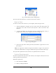
Fig. 10.2 The dialog of database backup 3. From the pull down menu, choose the drive where to save the backup files. For example, in the figure above, drive C is selected. 4. From the path menu, click and choose a folder to save the files. 5. There are two ways of selecting the database files. If you wish to back up all database files, click on “All” to select all database files. Also, clicking “Del All” removes the checks from selected database files.
Fig. 10.3 7. Now the backup files requested are saved in the location desired. Click “OK” to close the small window. 8. Click “Close” to close the window. Restore Database Files The option for restoring database files is located under the Maintenance menu. To restore the database, follow the steps as below: 1. Click on “Maintenance” and a menu appears. Fig. 10.4 Menu entry of database restore 2. Click on the “Restore Files” and a new window titled “Restore Files” appears.
Fig. 10.5 The dialog of database restore 3. From the pull down menu, choose the disk location where the restore files are located. 4. From the path menu, click and choose a specific path location of the restore files. 5. There are two ways of selecting the database files. If you wish to restore all database files, click on “All” to select all database files. Also, clicking “Del All” removes the checks from selected database files.
Fig. 10.6 7. Now the data from the database files are restored into the software. Click “OK” to close the small window. 8. Click “Close” to close the window. Purge Out-of-date Data The option for deleting old data is located under the Maintenance menu. Follow the steps below to purge the out-of-date data: 1. Click on “Maintenance” and a menu appears. 2. Click on the “Purge Old Records” and a new window titled “Clear outdate records” appears, shown as the following figure: Fig. 10.
• 1 Month: Delete all records older than one month. • 3 Month: Delete all records older than three month. • 6 Month: Delete all records older than six month. • 12 Month: Delete all records older than twelve month. • Arbitrary period: Delete all records from a given date. Note: The date given is in the format of Year-Month-Day: YYYY-MM-DD 4. Click “Delete Now” box to delete all records from that day. 5. A small box appears asking “Are you sure to delete the records?”.
Fig. 10.
Chapter 11 Event Log This chapter covers all Event Log issues. In this chapter, you will learn: • About each different type of log. • How to view event logs. • How to sort event logs. • How to search event logs. • How to print event logs. • How to export events logs to a file. Event Logs Information Under the main interface of control software, there are five different tabs. Each tab represents a different log. The software updates events and keeps track of them in these five different logs.
• Door: the door number at which the event occurred. • Type of entry/exit (In/Out): the type of event that occurred on the door. • Card No.: the number of the card used for that event. • Card Holder Photo: a picture of the card holder. Under the picture, more information is given about the card holder in the picture: Fig. 11.3 Cardholder photo in access granted log tab o Name: the name of the person in the picture shown. o Gender (Male/Female): the gender of the person shown in the picture.
• Name: the name of the card holder. • Controller: the address of the controller at which the event occurred. • Door: the door number at which the event occurred. • Type of entry/exit (In/Out): the type of event that occurred on the door. • Illegal Event:: the reason access was denied for a specific event. Some reasons include: cancel access request, unknown card, invalid door, invalid time zone, etc… • Card No.: the number of the card used for that event. 3. Operation Record Log: Fig. 11.
• Date (Month:Day:Year): the date the alarm event occurred. • Time (HH:MM:SS): the time the alarm event occurred. • Controller: the address of the controller at which the alarm event occurred. • Zone: the arm zone at which the alarm event occurred. • Event: the alarm event type that occurred on that particular controller. Some of the alarm events include: card reader number lost, fire alarm, door number forced open, defense alarm, etc… 5. Setting Record Log: Fig. 11.
Fig. 11.8 Access granted event logs 2. There are two ways to find information in an event log: • Scroll up or down using the scroll bars on the side and the bottom of the screen until the event is found. The arrow on the left is used to select and highlight a particular event. In case of the access granted tab, the arrow on the left, also, corresponds to the card holder picture on the right of the screen.
Sort Event Logs All the event logs in five different tabs can be sorted by the order specified by users. To sort the event logs, follow the steps as below: 1. Choose and click on one of the event log tab. For example, the “Access Granted” tab. 2. Click on the sort button at the toolbar and a new window appears. This option allows the user to narrow the event log(s) and find the event information easier.
Search Event Logs Users can search the events that they are interested in. How to search event logs is explained bellow. 1. Choose and click on one of the event log tab. For example, the “Access Granted”. 2. Click on the search button at the top of the tab. A dialog will be popped up shown as below. This option allows the user to narrow the event log and find the event information easier. The search criteria in the search window are: • Field: the specific field to search.
Fig. 11.10 Event search dialog 5. Click “Search” button to search the event log(s) accordingly. Or click “Close” to exit without searching the event log. Note: Only in the “access granted” search window, there is an option for the user to search both the access granted and the access denied event logs. • Checking the small box searches both the “access granted” and the “access denied” event logs. • Not checking the small box only searches the “access granted” event log.
Click Here to adjust Fig. 11.11 Adjust the event column width 4. Click on the print button at the top to bring up the print preview window. The computer running the EverAccess software must be connected to a printer to show the print preview window as below: Fig. 11.12 Event log print preview 5. Click on Zoom menu to change the zoom and be able to see more clearly. 6. Click on the print button at the top left corner of the screen to start printing. 7.
Fig. 11.13 Export a html file dialog • Give the file a file name and select the destination where to save the file • Click “Save” to export the event log in excel format. Or click “Cancel” to exit without saving. Export Event Logs The software can also allow users to export the event logs in one tab into an excel format file. How to export log event reports in excel format is explained bellow. 1. Choose and click on one of the event log tab. For example, the “Access Granted” tab. 2.
Fig. 11.14 Export an excel file dialog 4. Give the file a file name and select the destination where to save the file 5. Click “Save” to export the event log in excel format. Or click “Cancel” to exit without saving. Event Warning Message The software can prompt users a warning when there are either access granted events or alarm events generated. Once such an event happens, a warning dialog will be popped up to show the event. as shown in Fig. 11.
Fig. 11.
Chapter 12 Device Control This chapter covers all device control issues. In this chapter, you will learn: • Information about the Resources list. • How to remotely disarm or arm the system. • How to remotely set or reset the alarm. • How to remotely open doors. Resources List The resources list is located under the main interface of the control software and below the company logo. Fig. 12.
• Door 7 is connected to door 7 • Door 8 is connected to door 8. Fig. 12.2 A sample of fully expanded resource list Click a controller or a door in the list. The controller and the door will be shown in the remote device control interfaces that are explained as following sections. Remote Arm/Disarm: The remote arm/disarm option is located at the main interface of the software beside the resources list, shown as the figure below.
Fig. 12.3 Arm/Disarm control To remotely arm or disarm a particular controller: 1. Click the “+” to expand the controller list in the resource list to see all available controllers. 2. Click the controller address to select the controller. At this point, under the “Arm/Disarm” the controller address shows the corresponding selected controller. For example, controller at address 0001 is selected in the picture below. Fig 12.4 Expand the controller list 3.
Fig. 12.5 Arm/Disarm control Remote Set/Reset the Alarm: Users can remotely let a controller generate alarm or clear alarm, called set/reset alarm in the software. To remotely set or reset the alarm on a particular controller: 1. Click the “+” to expand the controller list in the resource list to see all available controllers. 2. Click the controller address to select the controller. At this point, under “Alarm”, the controller address shows the corresponding selected controller address.
2. Click the controller address to select the controller. 3. Click on the particular door to select the door to open. For example in the following figure, door 1 in controller 1 is selected. Fig. 12.7 Select a door in the resource list At this point, under “Doors”, the controller address shows the corresponding selected controller address. For example: Door name “Front door:” is selected as in the picture bellow. Controller at address 0001 is selected as in the picture bellow.
Fig. 12.9 Select a value for door open time 5. Click on the arrow to select whether the time in seconds, minutes or hours. Fig. 12.10 Select a time unit for door open time 6. Click “Open” to remotely open the selected door. When the time is up, the doors go back to their original status.
Chapter 13 Adding Company Logo and Door Status Check This chapter explains how to use EverAccess Flex software to add your own company logo, as well as, check door(s) status. The EverAccess Flex software allows for any company logo be placed in the software. The EverAccess Flex software allows the user to check if any door is open or closed at any given time. In this chapter you will learn: • How to change company logo. • How to check door status.
Fig 13.2 Company logo dialog 3. From the “Drive” menu, choose the disk location from which the Logo is located. 4. From the path menu, click and choose the particular file containing the company logo. 5. The name of the pictures should be shown under the “List” window. Click on the name to select the logo. Now the name of this logo picture appears under the “File Name” and the picture is previewed in “Image” window. Fig 13.3 Select an image in company logo dialog 6.
8. To cancel without any change of logo click “Cancel”. Fig 13.4 A sample of a new company logo Check Door Status The option for checking door status is located under the “Other” menu. The steps to check door status are explained as below: 1. Click on “Other” and a menu appears as below: Fig 13.5 Menu entry of door status checking 2. Click on the “Door Status Check” and a new window titled “Door Status Check” appears shown as the figure below.
Fig 13.6 Door status check dialog 3. To check the status of the all doors click on “Query”. A small computer indicating a search of status of all doors appears. When the search is done, all columns are updated on the window. The icon of an open door indicates the door is open The icon of a closed door indicates the door is closed At the bottom right hand corner you can see “Close”, “Open” status with numbers. The number next to “Close” indicates the number of doors closed.
Fig 13.6 A sample of door status check result 4. Click “Close” or click the X on the top right hand corner to exit the window.
Notes 115
Head Office 12F, No.79 Sec.1 Shin-Tai Wu Road, Hsi-Chi, Taipei, Taiwan Tel :+ 886-2-26982334 Fax :+ 886-2-26982380 European Office Albert-Einstein-Strasse 1, D-46446 Emmerich, Germany Tel : + 49-2822-9394-0 Fax : + 49-2822-939495 USA Office 1801 Highland Ave.Duarte,CA 91010 ,U.S.A Tel :+ 1-626-844-8888 Fax :+ 1-626-844-8838 Beijing office: Room 609,Technology Trade Building.