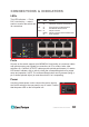
GIGABIT MANAGED ETHERNET SWITCH 8 PoE+ PORTS USER MANUAL Part #ESM308T000D ESM308T000D
This handy switch is designed to pass both data and electrical power to a number of PoE-compatible devices via standard Cat5e or Cat6 network cables. Easy-to-follow instructions in this user manual help make installation quick and simple, so you’ll also soon be enjoying the benefits of these additional features: • 10/100/1000 auto-sensing ports automatically detect optimal network speeds • IEEE 802.
CONTENTS CONNECTIONS & INDICATORS..........................................................................5 LEDs ...............................................................................................................5 Ports ...............................................................................................................5 Power ...............................................................................................................5 WEB-BASED BROWSER MANAGEMENT.............
SAFETY & COMPLIANCE STATEMENTS FEDERAL COMMUNICATIONS COMMISSION (FCC) STATEMENT This equipment has been tested and found to comply with the limits for a Class A digital device, pursuant to part 15 of the FCC Rules. These limits are designed to provide reasonable protection against harmful interference when the equipment is operated in a commercial environment.
CONNECTIONS & INDICATORS LEDs The LED indicators — Power, LED PoE, Link/Activity — make it Power easier to monitor the switch and its connections.
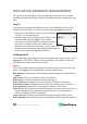
WEB-BASED BROWSER MANAGEMENT You can set up and manage the switch remotely by connecting it to a computer with Ethernet cable and using the switch’s Web-based browser management interface. Log In The advanced management capabilities of the switch can be accessed using a standard Internet browser. To access the Web-based management interface: 1. Activate your Web browser and enter the IP address 192.168.1.1 in the address field. 2.
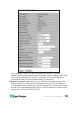
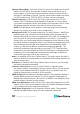
the IP address is static or dynamically assigned via DHCP. “Enabled” is a special case of a dynamically assigned IP address. DHCP is widely used in LAN environments to dynamically assign IP addresses from a centralized server, which reduces the overhead of administrating IP addresses. Fallback IP Address: XXX.XXX.XXX.XXX, where XXX ranges from 0 to 255. Default: 192.168.1.1. Specifies the IP address of this device.
Fallback Subnet Mask: XXX.XXX.XXX.XXX, where XXX ranges from 0 to 255. Default: 255.255.255.0. Specifies the IP subnet mask of this device. An IP subnet mask is a 32-bit number that is notated by using four numbers from 0 through 255, separated by periods. Typically, subnet mask numbers use either 0 or 255 as values (e.g., 255.255.255.0), but other numbers can appear. Fallback Gateway: XXX.XXX.XXX.XXX, where XXX ranges from 0 to 255. Default: 0.0.0.0. Specifies the default gateway IP address.
SNMP Write Community: Any 20 characters. Default: private. This parameter identifies the MIB tree(s) to which this entry authorizes write access. SNMP Trap Community: Any 20 characters. Default: public. This parameter identifies the MIB tree(s) to which this entry authorizes access for notifications.
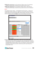
Power Saving Mode: When enabled, it adjusts the power provided to ports based on the length of the cable used to connect to other devices. Only sufficient power is used to maintain connection requirements. Link: Displays the current link status of each port: 1000MFDX, 100MFDX, 100MHDX, 10MFDX, 10MHDX or Down. The field lights green and shows the link speed if there is a valid connection on the port. Mode: Options are Auto Speed, 10 Half, 10 Full, 100 Half, 100 Full, 1000 Full and Disabled.
this system. Up to 16 VLAN groups can be defined. VLAN 1 is the untagged default VLAN. Modify: Click to complete the current VLAN configuration. Delete: Click to delete the current VLAN configuration. VLAN Setup The switch supports up to 16 VLANs based on the 802.1Q standard. From the VLAN Membership screen you can create and delete VLANs and change the VLAN port membership. VLAN Per Port Configuration This screen lets you change the VLAN parameters for individual ports or trunks.
Port: The number of the port or the ID of a trunk. VLAN Aware Enabled: When enabled (default is Disabled), the VLAN-aware ports are able to use VLAN tagged frames to determine the destination VLAN of a frame. VLAN-aware ports will strip the VLAN tag from received frames and insert the tag in transmitted frames (except for the PVID). VLAN-unaware ports will not strip the tag from received frames or insert the tag in transmitted frames.
Aggregation This screen lets you create port trunks so multiple links can be bundled to act as a single physical link for increased throughput, providing load balancing and redundancy of links in a switched inter-network. Actually, the link doesn’t have an inherent total bandwidth equal to the sum of its component physical links. Traffic in a trunk is distributed across an individual link in a deterministic method called a hash algorithm, which automatically applies load balancing to the ports.
providing load balancing and fault tolerance for uplink connections. LACP Port Configuration Port: Indicates the port number to be configured. Protocol Enabled: Enables LACP on the associated port. Key Value: Configures a port’s LACP administration key. The port administrative key must be set to the same value for ports that belong to the same link aggregation group (LAG). If this administrative key is not set when an LAG is formed (i.e.
RSTP Port Configuration Port: The port ID can’t be changed. “Aggregations” refers to any configured trunk group. Protocol Enabled: Click to enable (checked) or disable (default). When checked, you’re enabling RSTP for this port as per the configuration in the RSTP Port Configuration menu. Edge: The default setting is enabled (checked); click to disable (unchecked).
IGMP Configuration IGMP Enabled: When checked/selected, the switch will monitor network traffic to determine which hosts want to receive multicast traffic. Router Ports: Select if the port is connecting to the IGMP administrative routers. Unregistered IPMC Flooding enabled: Select this forwarding mode for unregistered (not-joined) IP multicast traffic. The traffic will flood when enabled (checked) and forward to router-ports only when disabled.
another switch port. This is commonly used for network appliances that require monitoring of network traffic, such as an intrusion-detection system. Mirroring Configuration Mirror Source: The port that will duplicate, or “mirror,” the traffic on the source port. Only incoming packets can be mirrored. Packets will be dropped when the available egress bandwidth is less than the ingress bandwidth. Mirror Port: Select the ports that you want to mirror, then click Apply.
QoS Mode: DSCP Packets are prioritized using the Differentiated Services Code Point (DSCP) value, a six-bit field that is contained within an IP (TCP or UDP) header. The six bits allow the DSCP field to take any value in the range 0 - 63. When QoS Mode is set to DSCP, the DSCP Configuration table is displayed, allowing you to map each of the DSCP values to a hardware output queue (low, normal, medium or high). The default settings map all DSCP values to the high-priority egress queue.
PoE (Power over Ethernet) Power over Ethernet (PoE) is deployed in applications where supplying AC power would be inconvenient, expensive or infeasible.
remotely control and centralized the power management simply by using a Cat5 cable to deliver both power and data. PoE Configuration PoE Enabled: When enabled (checked), you can use the port to supply power to the attached — and thus, powered — device (PD), which in turn allows you to remotely access that device and monitor its status. PD Class: This indicates the PD’s classification (Class 0-4). Delivering Power (W): This is the port’s output power. Current (mA): This is the port current.
Monitoring The Monitoring menu features the following subsections: Statistics Overview, Detailed Statistics, LACP Status, RSTP Status, IGMP Status, VeriPHY and Ping. Statistics Overview This screen lets you monitor traffic from any source port to a target port for real-time analysis. Detailed Statistics This screen provides additional details for fine-tuning your configuration.
LACP Port Status Protocol Active: Shows if the port is a member of an active LACP group. Partner Port Number: A list of the ports attached at the remote end of this LAG link member. Operational Port Key: Current operational value of the key used by this LAG. RSTP Status These screens allow you to confirm the current settings and operation of individual ports as they relate to the Rapid Spanning Tree Protocol (RSTP) configuration.
RSTP VLAN Bridge Overview Hello Time: Interval (in seconds) at which the root device transmits a configuration message. Max Age: The maximum time (in seconds) a device can wait without receiving a configuration message before attempting to reconfigure. All device ports (except designated ports) should receive configuration messages at regular intervals. Any port that ages out STA information (provided in the last configuration message) becomes the designated port for the attached LAN.
the switch detects another bridge connected to this port, the manual setting for Edge Port will be overridden and the port will instead function as a point-to-point (P2P) connection. P2P Port: Shows if this port is functioning as a point-to-point connection to exactly one other bridge. The switch can automatically determine if the interface is attached to a point-to-point link or to shared media. If shared media is detected, the switch will assume that it is connected to two or more bridges.
Ping This command sends ICMP echo request packets to another node on the network to determine if it can be reached. Possible results of the ping command: • Normal response: The normal response occurs in 1-10 seconds, depending on network traffic. • Destination does not respond: If the host does not respond, a “timeout” appears in 10 seconds. • Destination unreachable: The gateway for this destination indicates that the destination is unreachable.
Reboot Click Yes to restart the switch. The reset is complete when the Power LED stops blinking. Factory Default This function is to force the switch back to the original factory settings. To reset the switch, select Reset to Factory Defaults from the drop-down list and click Apply. The LAN IP Address, Subnet Mask and Gateway IP Address will be reset to their factory settings.
SPECIFICATIONS Standards • IEEE 802.1d (Spanning Tree Protocol) • IEEE 802.1p (Traffic Prioritization) • IEEE 802.1q (VLAN Tagging) • IEEE 802.1w (Rapid Spanning Tree Protocol) • IEEE 802.3ad (Link Aggregation) • IEEE 802.3 (10Base-T Ethernet) • IEEE 802.3ab (Twisted Pair Gigabit Ethernet) • IEEE 802.3ad (Link Aggregation Control Protocol LACP) • IEEE 802.3af (Power over Ethernet 802.3at Type 1) • IEEE 802.3at (Power over Ethernet 802.3at Type 2) • IEEE 802.3u (100Base-TX Fast Ethernet) • IEEE 802.