GIGABIT MANAGED ETHERNET SWITCH 16 P oE+ PORTS PLUS TWO SFP PORTS USER MANUAL Part #ESM316T002R ESM316T002R
Content CHAPTER 1 The Introduction ................................................................................ 5 Web Browser ........................................................................................................ 5 Logging In............................................................................................................. 6 CHAPTER 2 System ............................................................................................... 8 System Information ...............
Packet Scheduling Setting.................................................................................. 32 LLDP Configurations .......................................................................................... 33 LLDP Neighbors ................................................................................................. 34 SNMP Setting ..................................................................................................... 35 Trap Receivers Setting ..............................
ABOUT THIS GUIDE This guide provides information about how to operate and use the management functions of the Web Management Switch.
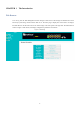
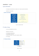
CHAPTER 1 The Introduction Web Browser You can log into the Web Management Switch through a Web browser and manage and maintain the switch intuitively by interacting with the built-in Web server. The home page is displayed as shown below. It displays the Main Menu on the left side of the screen and an image of the front panel on the right side. The Main Menu is used to navigate to other menus, and display configuration parameters and statistics.
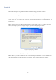
Logging In Please follow the steps to configure this Web Smart switch. The configure procedure is as follows: Step 1: Use Ethernet Category 5 cable to connect this switch to your PC. Step 2: Check that your PC has an IP address on the same subnet as the switch. For example, the PC and the switch are on the same subnet if they both have addresses that start 192.168.1.x. The subnet mask is 255.255.255.0. Step 3: Open the browser (like Microsoft Internet Explorer) and go to http:// 192.168.1.
Figure 3: Web-Based Management Interface 7
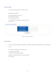
CHAPTER 2 System System Information To lookup System Information in the Web browser, click System, then Information. Web Smart switch interface Figure 4: System Information IP Address Setting To set up static IP address of the switch. Web Smart switch interface 1. Click System, then IP Setting. 2. Set the Mode to “Static IP”. 3. Specify the IP address, subnet mask, and gateway address. 4. Click Apply.
IPv6 Address Setting IPv6 is an Internet Layer protocol for packet-switched internetworking and provides end-to-end datagram transmission across multiple IP networks. IPv6 includes two distinct address types; link-local unicast and global unicast.
User Account To set up the System Password in the Web browser: Web Smart switch interface 1. Click System, then User Account. 2. Enter the new user name. 3. Enter the new password. 4. Enter the new password again to confirm your input. 5. Click Save. Figure 7: User Account Setting Port Setting To specify options for enabling auto-negotiation or manually setting the speed and duplex mode, or enabling flow control. To set up port configuration in the Web browser: 1. Click System, Port Setting. 2.
Figure 8: Port Setting Hint§ The following parameters are displayed on the Port Setting configuration: ■ Port—Set up one or more ports. Hold down the CTRL key and click port numbers to select multiple ports. Hold down the SHIFT key to select a range of ports. ■ State—Set the link state of port interfaces. (Default: Enabled) ■ Speed/Duplex—Configure the port speed and duplex mode using auto-negotiation or manual selection. (Default: Auto-negotiation enabled) ■ Auto - Enable auto-negotiation.
CHAPTER 3 Configuration Trunk Group Setting To configure a trunk group. Web Smart switch interface 1. Click Configuration, Link Aggregation, Trunk Group Setting. 2. Select the trunk group ID to be created or modified. 3. Select the trunk type; Static or LACP. 4. Assign up to four port members to the trunk. 5. Click Add/Modify.
Trunk Distribution Algorithm Setting To configure a trunk’s load-balancing settings. Web Smart switch interface 1. Click Configuration, Link Aggregation, Trunk Setting. 2. Select the trunk group ID to be configured or modified. 3. Select the trunk Distribution Algorithm Parameters as required. 4. Click Apply. Figure 10: Trunk Distribution Algorithm Setting Hint§ The switch provides five load-balancing methods to distribute a balanced load across all links in a trunk.
■ Destination MAC - All traffic with the same destination MAC address is output on the same link in a trunk. This mode works best for switch-to-switch trunk links where traffic through the switch is destined for many different hosts. Do not use this mode for switch-to-router trunk links where the destination MAC address is the same for all traffic. ■ Source IP - All traffic with the same source and destination IP address is output on the same link in a trunk.
LACP Setting The LACP (link aggregation control protocol) dynamically aggregates ports and removes aggregations. LACP interacts with its peer by sending LACPDUs (link aggregation control protocol data units). Web Smart switch interface To arrange LACP settings, 1. Click Configuration, Link Aggregation, LACP Setting. 2. Enable LACP on the switch. 3. Specify the LACP System Priority to identify LAGs (link aggregation group) on the switch. 4. Click Apply.
Static VLAN Table Setting The VLAN (virtual local area network) technology is developed for switches to control broadcast operations in LANs. By creating VLANs in a physical LAN, you can divide the LAN into multiple logical LANs, each of which has a broadcast domain of its own. Hosts in the same VLAN communicate with each other as if they are in a LAN. However, hosts in different VLANs cannot communicate with each other directly. In this way, broadcast packets are confined within a VLAN.
■ VLAN Name – Name of the VLAN (1-100 characters) VLAN Port Setting Arranging VLAN attributes for specific interfaces, including the default Port VLAN identifier (PVID). Web Smart switch interface To specify attributes for VLAN port members, 1. Click Configuration, VLAN, VLAN Setting. 2. Select one or more ports or trunks to configure. 3. Configure the required PVID setting. 4. Click Apply.
VLAN-Stacking Table Setting Set the stacking VLAN membership for selected interfaces to be part of the Service Provider VLAN (S-VLAN), that is uplink ports for a 802.1Q Tunnel. This stacking VLAN is used to segregate and preserve customer VLAN IDs for traffic crossing the service provider network. The switch supports up to 64 S-VLAN IDs. Web Smart switch interface To manage stacking VLAN port members, 1. Click Configuration, VLAN Stacking, S-VLAN Table. 2. Specify the S-VLAN ID number. 3.
Vlan Stacking Setting After configuring port members for stacking VLANs on the switch, the ports connected to a service provider network need to be enabled as doubled tagged ports. Also the Tag Protocol Identifier (TPID) value must be set for the doubled-tagged ports to identify 802.1Q tagged frames. Web Smart switch interface To manage stacking VLAN port settings, 1. Click Configuration, VLAN Stacking, S-VLAN Setting. 2. Specify the Tag Protocol ID number. 3.
Hint§ The following parameters are shown on the VLAN-Stacking Table Setting: ■ Tag Protocol ID - Tag Protocol Identifier specifies the Ether type of incoming packets on a tunnel port. (Range: 0x0600~0xFFFF hexadecimal, Default: 0x88a8) ■ PVID - The stacking VLAN Port VLAN Identifier. The PVID determines the stacking VLAN tag for single-tagged packets forwarded to an enabled S-VLAN port. ■ Provider Network Port - Set the S-VLAN membership mode for the selected interface.
IGMP Multicast Group Information To display multicast group and router port information, click Configuration, IGMP Snooping, Multicast Entry Table. The IGMP Multicast Router Information table displays the current multicast groups learned through IGMP Snooping. Multicast routers that are attached to ports on the switch use information obtained from IGMP, along with a multicast routing protocol such as DVMRP or PIM, to support IP multicasting across the Internet.
IGMP Snooping IGMP Snooping (Internet Group Management Protocol Snooping) is a multicast constraining mechanism that runs on Layer 2 switch to manage and control multicast groups.
IGMP Global Setting Web Smart switch interface To manage IGMP Snooping global settings, 1. Click Configuration, IGMP Snooping, IGMP Snooping Setting. 2. Enable IGMP Snooping on the switch. 3. Modify other IGMP global settings as required. 4. Click Update. Hint§ The following parameters are shown on the IGMP Snooping global settings page: ■ IGMP Snooping - When enabled, the switch will monitor network traffic to determine which hosts want to receive multicast traffic.
IGMP VLAN Setting Web Smart switch interface To manage IGMP Snooping settings, 1. Click Configuration, IGMP Snooping, IGMP Snooping Setting. 2. Specify the VLAN ID. 3. Enable IGMP Snooping on the VLAN. 4. Enable IGMP Querier on the VLAN if you want this switch to be elected as querier. 5. Click Apply. Hint§ The following parameters are shown on the IGMP Snooping VLAN settings page: ■ VLAN ID - Specify the ID of a configured VLAN on the switch. (Range: 1-4094) ■ VLAN Name - Display the name of the VLAN.
Spanning Tree The spanning tree protocol is used to eliminate loops in a local area network. A switch running this protocol detects any loop in the network by exchanging information with one another and eliminates the possible loop by blocking certain ports until the loop network is pruned into a loop-free tree, thereby avoiding infinite recycling of packets in a loop network. Web Smart switch interface To manage global settings for Spanning Tree, 1. Click Configuration, Spanning Tree, STP Global Setting.
configuration messages at regular intervals. Any port that ages out STP information (provided in the last configuration message) becomes the designated port for the attached LAN. If it is a root port, a new root port is selected from among the switch ports attached to the network. (Note that references to “ports” in this section mean “interfaces,” which includes both ports and trunks.
Spanning Tree Port Setting Use the STP Port Setting page to configure Spanning Tree attributes for specific interfaces, including path cost, port priority, edge port (for fast forwarding), automatic detection of an edge port, and point-to-point link type. Web Smart switch interface To configure port settings for Spanning Tree, 1. Click Configuration, Spanning Tree, STP Port Setting. 2. Modify the required attributes for one or a group of ports. 3. Click Apply.
is detecting network loops. Where more than one port is assigned the highest priority, the port with lowest numeric identifier will be enabled. (Range: 0-240, in steps of 16; Default: 128) ■ P2P - The link type attached to an interface can be set to automatically detect the link type, or manually configured as point-to-point or shared medium. Transition to the forwarding state is faster for point-to-point links than for shared media.
Quality of Service (QoS) QoS is the evaluation on the service ability of network delivery or on the capacity of dealing with situations such as delay, delay jitter and packet loss rate in packet delivery. Port-based Priority Setting Management of the default port priority for each port on the switch. Web Smart switch interface To configure global settings for Spanning Tree: 1. Click Configuration, QoS, Port-based Priority. 2. For one or a group of ports, set the default priority value. 3. Click Apply.
DSCP-based Priority Setting The Differentiated Services Code Point (DSCP) is a six-bit field in the IP header, allowing coding for up to 64 different forwarding behaviors. The DSCP replaces the ToS bits, but it retains backward compatibility with the three precedence bits so that non-DSCP compliant, ToS-enabled devices, will not conflict with the DSCP mapping. Based on network policies, different kinds of traffic can be marked for different kinds of forwarding.
Priority to Queue Mapping Setting The QoS technique known as class of service (CoS), is a 3-bit field within an Ethernet frame header when using tagged frames on an 802.1 network. So up to eight separate traffic priorities are defined in IEEE 802.1p. Always can map the priority levels to the switch’s output queues in any way that benefits application traffic for our own network. Web Smart switch interface To configure port-level DSCP remarking, 1. Click Configuration, QoS, Priority to Queue Mapping. 2.
Packet Scheduling Setting You can set the switch to service the queues based on a strict rule that requires all traffic in a higher priority queue to be processed before lower priority queues are serviced, Weighted Fair Queuing (WFQ), or Weighted Round-Robin (WRR) queuing that specifies a relative weight of each queue. The traffic classes are mapped to one of the eight egress queues provided for each port. You can assign a weight to each of these queues (and thereby to the corresponding traffic priorities).
to the sum of the weights of all queues. (This is the default selection.) ■ Weight-round-robin - Share bandwidth at the egress ports by using the scheduling weights for queues 1 through 8 respectively. WRR specifies a relative weight for each queue that determines the percentage of service time the switch services each queue before moving on to the next queue. ■ Queue ID - Output queue buffer. (Range: 1-8, where 8 is the highest priority queue) ■ Weight - Set a new weight for the selected traffic class.
■ LLDP Status - Enable LLDP on the switch. (Default: Disabled) ■ Transmission Interval - Configure the periodic transmit interval for LLDP advertisements. (Range: 5-32768 seconds; Default: 30 seconds) This attribute must comply with the following rule: (Transmission Interval * Transmission Hold Time) ≤ 65536, and Transmission Interval ≥ (4 * Transmission Delay) ■ Hold Time Multiplier - Configure the time-to-live (TTL) value sent in LLDP advertisements as shown in the formula below.
SNMP Setting SNMP (Simple Network Management Protocol) monitor network switches through TCP/IP protocol suite. It offers automatic network management and avoids the physical differences between various switches, and thus provides automatic management of products from different manufacturers. Web Smart switch interface To specify SNMP system settings: 1. Click Configuration, SNMP Setting. 2. Enable SNMP for the switch. 3. Configure the Name, Location, and Contact information. 4.
Hint§ The following parameters are shown on the SNMP Setting, Community Strings Setting. ■ SNMP Status - Enable or disable SNMP service. (Default: Disabled) ■ System Name - A name assigned to the switch system. ■ System Location - Specify the system location. ■ System Contact - An administrator responsible for the system. ■ String – A community string that acts like a password and permits access to the SNMP protocol.
Port Mirroring Setting Port mirroring includes local mirroring groups, remote source mirroring groups and remote destination mirroring groups. Web Smart switch interface To configure port mirroring: 1. Click Configuration, Port Mirroring. 2. Select the Mirror Set Index. 3. Select the Mirror Direction. 4. Select the Mirroring (target) port. 5. Select the one or more mirrored (source) ports. 6. Click Apply. Figure 27: Port mirroring Hint§ The following parameters are shown on the LLDP Neighbors page.
Port Security Setting Port security is a feature that allows you to configure a switch port with a maximum number of MAC addresses that are authorized to access the network through that port. When port security is enabled on a port, the switch stops learning new MAC addresses on the specified port when it has reached a configured maximum number.
■Maximum L2 Entry — The maximum number of MAC addresses that can be learned on a port. (Range: 0 16447, where 0 means disabled) ■Action — Indicate the action to be taken when a port security violation is detected: ■ Trap to CPU: Send an SNMP trap message. (This is the default.) ■ Drop: Drop other traffic from the port. ■ Forward: No action is taken. Traffic is forwarded as normal.
Bandwidth Control Setting This function allows the network manager to control the maximum rate for traffic received on a port or transmitted from a port. Rate limiting is configured on ports at the edge of a network to limit traffic into or out of the switch. Packets that exceed the acceptable amount of traffic are dropped. Rate limiting can be applied to individual ports or trunks. When an interface is configured with this feature, the traffic rate will be monitored by the hardware to verify conformity.
■Type - Specify ingress or egress traffic. (Default: Ingress) ■State - Enable or disable the rate limit. (Default: Disabled) ■Rate (Kbit/sec) - Set the rate limit level.
Jumbo Frame Setting The switch provides more efficient throughput for large sequential data transfers by supporting jumbo frames up to 9216 bytes. Web Smart switch interface To configure Jumbo Frames: 1. Click Configuration, Jumbo Frame. 2. Select the frame size to configure. 3. Click Apply. Figure 30: Jumbo Frame Setting Hint§ The following parameters are shown on the LLDP Neighbors page. ■Jumbo Frame (Bytes) - Configure support for jumbo frames.
Management Access Filter To create up to eight IP addresses or IP address groups that are allowed access to the switch through the Web browser. Web Smart switch interface 1. Click Configuration, Management Access Filter. 2. Enter an IP address 3. Specify a netmask to define a single IP address, or an address range. 4. Select the table entry to activate the filter. 5. Click Apply. Figure 31: Management Access Filter Hint§ The following parameters are shown on the LLDP Neighbors page.
Power over Ethernet Setting Power over Ethernet (PoE) means that power sourcing equipment (PSE) supplies power to powered devices (PD) such as IP telephone, wireless LAN access point, and web camera from Ethernet interfaces through twisted pair cables. Web Smart switch interface 1. Click Configuration, Power over Ethernet. 2. Select the port number of the connected PD. 3. Specify the PD on. 4. Click Apply.
CHAPTER 4 Security MAC Address Information To display the MAC address forwarding table. Web Smart switch interface 1. Click Configuration. 2. Then click Security, MAC Address, MAC Forwarding Table. Figure 33: MAC Address Information Hint§ The following parameters are shown on the MAC Address Information page. ■No. - The number of the address entry in the forwarding table. ■MAC Address - Physical address associated with this interface. ■VLAN ID - The ID of a configured VLAN (1-4094).
Static MAC Setting A static address can be assigned to a specific interface on the switch. Static addresses are bound to the assigned interface and will not be moved. Web Smart switch interface To configure static MAC addresses: 1. Click Security, MAC Address, Static MAC. 2. Specify the MAC address to be statically assigned. 3. Specify the VLAN ID. 4. Select the port or trunk interface for the static assignment. 5. Click Add.
MAC Filtering Setting The MAC Filtering pages are used to filter service to clients attempting to access the Internet based on protocol type, destination/source MAC address, and the direction of traffic for each packet. Web Smart switch interface To configure MAC Address Filtering: 1. Click Security, MAC Address, MAC Address Filtering. 2. Specify the MAC address to be filtered. 3. Specify the VLAN ID. 4. Select to filter the MAC address as the source, destination, or both. 5.
802.1x Setting The 802.1X protocol provides port authentication. The 802.1X protocol must be enabled globally for the switch system before port settings are active. Web Smart switch interface To configure 802.1X global settings: 1. Click Security, 802.1X, 802.1X Setting. 2. Set 802.1X to Enabled. 3. Specify the RADIUS server IP address. 4. Specify the RADIUS server shared key. 5. Modified other parameters as required. 6. Click Apply. Figure 36: 802.
802.1x Port Setting When 802.1X is enabled, you need to configure the parameters for the authentication process that runs between the client and the switch (that is, authenticator), as well as the client identity lookup process that runs between the switch and authentication server. Web Smart switch interface 1. Click Security, 802.1X, 802.1X Port Setting. 2. Select one or more ports to configure. 3. Set the 802.1X Mode to “Authentication.” 4. Click Apply. Figure 37: 802.
IP Filter Configurations IP Filter Security is a feature that filters IP traffic on port interfaces based on manually configured entries in the IP Filter table, or allowed IP address assignment through DHCP. IP Filter Security can be used to prevent traffic attacks caused when a host tries to use the IP address of a neighbor to access the network. Web Smart switch interface To configure IP Filter settings: 1. Click Security, IP Filter Setting. 2. Select one or more ports to configure. 3.
■IP Address — An IP address, or an address specifying a range, that is allowed access through the switch. ■IP Netmask — A mask that specifies a single IP address, or defines a range of IP addresses. (Default: 255.255.255.0) ■DHCP Server Allowed — Permit traffic from a DHCP server through the specified ports.
Storm Control settings Broadcast storms may occur when a device on your network is malfunctioning, or if application programs are not well designed or properly configured. If there is too much broadcast traffic on your network, performance can be severely degraded or everything can come to complete halt. You can protect your network from broadcast storms by setting a threshold for broadcast traffic. Any broadcast packets exceeding the specified threshold will then be dropped.
Port Isolation The feature provides port-based security and isolation of local ports. The switch isolates port traffic by specifying those ports to which it can forward or receive traffic. Web Smart switch interface To configure Port Isolation settings: 1. Click Security, Port Isolation. 2. Select one or more ports to configure. 3. Select one or more ports to which traffic can be forwarded and received. 4. Click Apply.
Defence Engine Defence Engine is a advanced feature that can prevent switch’s CPU from being overwhelmed by flooded packets, such as unknown unicast, unknown multicast, or broadcast packets. This function can be used to prevent malicious viruses or worm attacks. Web Smart switch interface To configure Defence Engine settings: 1. Click Security, Defence Engine. 2. Set Defence Engine status to Enabled. 3. Click Apply.
CHAPTER 5 Monitoring Port Statistics Information You can display standard statistics on network traffic passing through each port. This information can be used to identify potential problems with the switch, such as a faulty port or unusually heavy loading. All values displayed have been accumulated since the last system reboot. Web Smart switch interface To click Monitoring, Port Statistics to display port statistics.
CHAPTER 6 Tools Http Upgrade Use the HTTP Upgrade page to upgrade the switch’s system firmware by specifying a new software file. You can also use the HTTP Upgrade page to save the current configuration to a file on your computer, or to restore previously saved configuration settings to the switch. Web Smart switch interface To upgrade switch software: 1. Click Tools, HTTP Upgrade. 2. Click the Browse button, and select the firmware file. 3. Click the Upgrade button to upgrade the switch’s firmware.
Reset Factory Defaults To restore factory defaults. Web Smart switch interface To click Tools, Reset, then click the Reset button. The reset will be complete when the Web browser displays the login page.
Reboot To restart the switch. Web Smart switch interface To click Tools, Reboot, then click the Reboot button. The reboot will be complete when the web interface displays the login page. Figure 45: Reboot SPECIFICATIONS Standards • IEEE 802.1d (Spanning Tree Protocol) • IEEE 802.1p (Traffic Prioritization) • IEEE 802.1q (VLAN Tagging) • IEEE 802.1w (Rapid Spanning Tree Protocol) • IEEE 802.
• Backplane speed: 36 Gbps • Switch architecture: store and forward • Configuration options: -‐ Port link speed: 10 Mbps, 100 Mbps, 1000 Mbps or auto-‐negotiation -‐ PoE on/off per port -‐ Flow control on/off per port -‐ VLAN -‐ Rate limiting (ingress rate and egress rate) -‐ Port Mirroring -‐ Port Aggregation/LACP: 8 groups -
60