IP 99 Series EVS110 1CH Video Server EIP220 Network Camera User’s Manual Copyright © EverFocus Electronics Corp, Version Release: Dec.
IP99 series Product Name: IP99 EverFocus Network Cameras Model Number(s): EVS110, EIP220 FCC Notice "Declaration of Conformity Information" This equipment has been tested and found to comply with the limits for a Class A digital device, pursuant to part 15 of the FCC Rules. These limits are designed to provide reasonable protection against harmful interference in a residential Installation.
IP99 series About this document All the safety and operating instructions should be read and followed before the unit is operated. This manual should be retained for future reference. The information in this manual was current when published. The manufacturer reserves the right to revise and improve its products. All specifications are therefore subject to change without notice. Safety Notice -These limits are designed to provide reasonable protection.
IP99 series power source ratings. Do not use the appliance in an extreme environment where high temperature or high humidity exists. Use the appliance at temperature within -10℃ ~ 50℃ / 14℉ ~ 122℉ and a humidity below 90%. The input power source for this appliance is 12VDC. Use only the recommended power supplies. Power supplies must comply with the requirement of the latest version of IEC60950-1. Substitutions may damage the unit or cause a fire or shock hazard. Electrostatic-sensitive device.
IP99 series For example: (This web site may change without notices.) http://www.microsoft.
IP99 series TABLE OF CONTENTS 1. STARTING THE CAMERA OR VIDEO SERVER ............................................. 7 1.1 INSTALL IP99 SEARCHER IN PC ............................................................................. 7 1.2 ASSIGN NEW IP ADDRESS (OPTIONAL) .................................................................. 7 1.3 ACCESSING THE CAMERA ...................................................................................... 8 1.4 RESET AND FACTORY DEFAULT ................................
IP99 series 3.12 PTZ SETTING ..................................................................................................... 26 3.13 ADMINISTRATOR ............................................................................................... 27 3.14 CHANGE PASSWORD .......................................................................................... 28 3.15 SPECIAL SETTING............................................................................................... 28 3.16 MAINTENANCE .........
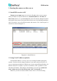
IP99 series 1. Starting the camera or video server 1.1 Install IP99 searcher in PC Though you can simply enter 192.168.1.99 in IP address bar to access camera when you connect to only one IP99 device.( Default IP address is: 192.168.1.99 Port is: 80). However, it is recommended that you use IP search to manage IP camera and encoder. Please insert CD to install IP99 searcher tool. After finishing installation, click “IP searcher” icon to find IP99 encoders and cameras.
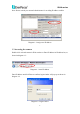
IP99 series Note: Please consult your network administrator for avoiding IP address conflict Diagram 1.2 Assign new IP address 1.3 Accessing the camera Double click selected camera in IP99 searcher or Enter IP address in IP address bar, as shown in diagram 1.3: Diagram 1.3 enter IP address Enter IP address and click Enter to confirm, login window will pop up as shown in diagram 1.4: Diagram 1.
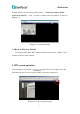
IP99 series In login window, enter user name and password, (default user name is admin, password is 11111111). Click“Confirm"button to enter web window, as shown in diagram 1.5: Diagram 1.5 Camera Web page 1.4 Reset and Factory Default You can physically push” RST” button on IP99 camera or click “Default” on IP searcher to back to factory default. 2.
IP99 series 2.1 Add more videos If you wish to add one video display in the same web page, click “Add New” button, as shown in diagram 2.2: Diagram 2.2 Add video display 2.2 Change video resource You can change video resource and simultaneously view multiplies cameras and encoders at same time. Right click mouse on display center point and go to “Change Resource”. Then you would see the login page. Enter IP address, user name, password for the camera you want to add.
IP99 series 2.3. Edit and Change Display Layout 2.3.1 Edit layout If you wish to add more video displays, please click changes to , then interface ,you can freely set the layout of video display in this window. Enter the number of channels you want for each row. Use comma to separate them. And click to make the actual layout change. For example,”5,3,0”, “shows the following layout. As shown in diagram 2.4: Diagram 2.4 Display re-layout After editing layout, click “Save” button to save settings.
IP99 series Diagram 2.5 Layout selection 2.4 Zoom in/zoom out 2.4.1 Integer zoom in/zoom out Click buttons at top right side of the page to zoom in or zoom out the entire screen. 2.3.2 Single display zoom in/zoom out To zoom in/zoom out single channel screen, direct the mouse to that channel display, and click on at top of , slide the tilt wheel of mouse to zoom in or zoom out video images. 2.
IP99 series Diagram 2.6 Record 2.4.2 Stop recording Method 1: Click on button located at top right corner of the image, it will stop recording immediately, button changes to . Method 2:Double click on the green area of , it returns to original color meaning that recording is stopped. 2.4.3 Snapshot Click button to snapshot the image,default file path for the snapshot is: C:\image99\... 2.4.4 Playback Click button,playback window pops up as shown in diagram 2.7: Diagram 2.
IP99 series Click “Search NVR"button to search the NVR device used for archiving recording files. If you do not have NVR device, please ignore this selection. Open the file to be played, click “Play"to play recorded video. ¾ Click fast forward button , to adjust playback speed. ¾ Click fast reverse button , to adjust reverse speed. ¾ Click pause button ¾ Click play button , to pause the video. , to stop playback, returning to normal page.
IP99 series Note 2:PTZ control can also be preformed by using PC’s keyboard, please refer to section 5 of 2.4.7 for more details. Note3: PTZ control is functioning only if PTZ Function is set On in PTZ Setting, please refer to section 3.12. 2.4.6 On-Screen PTZ Control (for Video Server only) On Screen PTZ function is available when you connect PTZ to IP99 video server or use IP99 PTZ.
IP99 series Diagram 2.10 Display size 2)Change source: Click“Change source"to fill out information for the IP camera to be controlled, as shown in diagram 2.11: Diagram 2.11 Change source First row: Camera name Second row: IP address of camera to be connected Third row: User name Fourth row: Login password When you finish filling out, click on“Change"button to enter video display with setting changed. If you do not need to change those settings, please click “Abort” to exit from this page.
IP99 series 4)Sound ON:used to enable/disable sound transmission. 5)PTZ(for Video Server only):Click “PTZ"option which allows you to check keyboard keys of PC used to control speed dome, as shown in diagram 2.13: Diagram 2.13 PTZ contraol keys and functions 6)File .av to AVI:Click“File .av to AVI"option, select .av file to be converted and click “Confirm” to save it as AVI format. Diagram 2.14 File .av to AVI confirmation dialogue box Note:AVI is the most widely used playback format. 3. System setting 3.
IP99 series Diagram 3.1 status information 3.2 Video/audio setting Select 2. Video & Audio from the drop-down menu at top right corner, as shown in diagram 3.2: Diagram 3.2 Video & Audio settings Enable settings for video stream, snapshot, OSD, Record and Audio. 1)CBR setting: Set CBR enabled or disabled, default value is Disable. Note: CBR is fixed ratio.
IP99 series 2)Resolution: Set record resolution D1: 720x480 (NTSC) / 720x576 (PAL) Half D1: 720x240 (NTSC) / 720x288 (PAL) CIF: 352x240 (NTSC) / 352x288 (PAL) QCIF: 176x120 (NTSC) / 176x144 (PAL) 3)Limit frame rate to: Set frame rate according o resolution. 4)OSD setting: Set OSD text and font size. 5)Record: Set REC File path, REC file Duration Time and REC Disk Overwrite at.
IP99 series Diagram 3.3(b)Device setting Diagram 3.3(b)shows the functions of IP camera, it is for IP camera NOT for Video Server. It has some additional functions compared to other cameras, as shown in diagram 3.3 (c): Diagram 3.3(c)Extension functions of device setting Mirror: Enable or Disable Mirror function by selecting ON/OFF. Shutter Speed: Control exposure time by changing shutter speed value. If lighting source is sufficient enough, the exposure time required is less.
IP99 series selected area, click “Remove region”. Please refer to diagram 3.4: Diagram 3.4 Alarm event 1)Motion detection event: No event, send JPEG file by e-mail or upload to FTP. Note: When sending JPEG by e-mail or upload to FTP, file will be sent to the assigned e-mail adress. 2)Alarm I/O setting: Set Alarm Input/Output setting and status, as shown in diagram 3.5: Select Alarm input level high, low or no alarm for each AI alarm inputs.
IP99 series 3.5 Networking Set camera’s IP address, DNS setting, HTTP port information, as shown in diagram 3.6: Diagaram 3.6 Networking DHCP will automatically get the IP address. If you are not using DHCP, you can manually assign IP address and port. Primary DNS server has to be the same as HTTP port set in IP address. Default HTTP port is 80.
IP99 series 3.6 Wireless LAN Assignment will be made according to local wireless router, as shown in diagram 3.7: Diagram 3.7 Wireless settings 3.7 PPPOE setting Select whether to enable PPPoE function. If PPPoE function is enabled, please enter user name and password: Diagram 3.
IP99 series When network is connected, it will show IP address, default router and DNS server after connection in status section. Enable“Email notification when IP is changed"function, so when the system re-connects to network, it will automatically notify the IP address to user by e-mail. 3.8 DDNS setting Dynamic DNS setting as shown in diagram 3.9: Diagram 3.9 DDNS setting IP99 series cameras support 3 DDNS servers: DynDNS, PeanutHull and Perfecteyes.
IP99 series Diagram 3.10 SMTP setting Enter user name and password of login mail server. Once SMTP is set, it can be used when snapshot, alarm and PPPoE are enabled. 3.10 FTP setting Select “FTP server setting"page, as shown in diagram 3.11: Diagram 3.
IP99 series Set FTP server, user name, password, FTP command port and path & file name. User can upload recorded video and event file to FTP server. 3.11 Date & Time setting Set camera’s current date, time and time zone, as shown in diagram 3.12: Dirgram 3.12 Date & Time settings 3.12 PTZ setting Define PTZ protocol, PTZ baud rate and PTZ address, as shown in diagram 3.
IP99 series Diagram 3.13 PTZ settings Since IP address is the only fixed one, therefore PTZ address is set as “1”. Protocols are Pelco-D and Pelco-P which are in common use. Note: When using Everfocus speed dome, user only needs to set the protocol as AUTO in order to control the speed dome. 3.13 Administrator Add user, set user’s right, set maximum number of simultaneous viewers and change camera name, as shown in diagram 3.
IP99 series Diagram 3.14 Management 3.14 Change password Change user’s login password, as shown in diagram 3.15: Diagram 3.15 change password 3.15 Special setting Set compression, set camera type and transform to AVI format, as shown in diagram 3.
IP99 series Diagram 3.16 Special setting Default compression rate is 8. The lowest compression rate is 5 for clearer image. compression 15 is the highest rate for smoother image. 3.16 Maintenance Maintenance and system upgrade, as shown in diagram 3.17: Diagram 3.17 Maintenance server and Upgrade server Note: Please only use *.img file provided by Everfocus to upgrade firmware. Everfocus will not be responsible for any damage or loss caused by usage of firmware provided by the third party.
IP99 series 4. Frequently Asked Questions 4.1 I have problem recording and playback on Windows Vista. Answer: You need to turn off User Account Control (UAC) 1. Open Control Panel. 2. Under User Account and Family settings click on the "Add or remove user account". 3. Click on one of the user accounts, for example you can use the Guest account. 4. Under the user account click on the "Go to the main User Account page" link. 5.
IP99 series EverFocus Electronics Corp. China Office: Room B-05D-1, KESHI PLAZA, Shangdi Information Industry Base,Haidian District, Beijing China 100085 TEL: +86-10-62973336/37/38/39 FAX: +86-10-62971423 www.everfocus.com.cn Head Office: 12F, No.79 Sec. 1 Shin-Tai Wu Road, Hsi-Chi, Taipei, Taiwan TEL: 886-2-26982334 FAX: 886-2-26982380 www.everfocus.com.tw USA Office: 1801 Highland Ave. Unit A Duarte, CA 91010, U.S.A. TEL: +1-626-844-8888 FAX: +1-626-844-8838 www.everfocus.