
Full Product Manual


26
1 S
DC
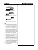
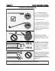
EXAMPLE 2
Welding Amps: 100 amps
Pulse Amps: 50%
Pulse Time On : 50%
DC Pulse Frequency: 25Hz
AMPS
100
50
EXAMPLE 1
Welding Amps: 100 amps,
PulseAmps: 50%
Pulse Time On: 50%
DC Pulse Frequency: 1 Hz
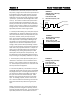
EXAMPLE 3
Welding Amps: 100 amps
Pulse Amps: 25%
Pulse Time On: 75%
DC Pulse Frequency: 3 Hz
AMPS
DC
1 S
25
100
2 S
AMPS
DC
1 S
3 S
50
100
Pulse Amps
Welding Amps
Pulse Time ON
Pulse Hz
6. Standard Pulse. (AC and DC) The pulse creates two
amp values, a high and a low value that cycle back and
forth between each other while welding. The upper
amperage is called the “welding amps” (somemes
called peak current) and the lower amperage is called
“pulse amps “ (somemes called background or base
current). This creates a situaon where penetraon
can be achieved without overheang the metal, par-
cularly on metals that are prone to structural deteri-
oraon or burn through. In eect you are creang an
average of amps. The PowerTIG series feature three
adjustable parameters concerning the pulse:
1. Pulse Amps. Both welding amps and pulse amps are
independently set. Adjust the welding amps with the
main control knob and the pulse amps with the pulse
amp knob. However, when you adjust the pulse
amps, you are actually dening a xed rao of amps.
This is expressed as a percentage of Welding Amps.
The display is not synchronized with the pulse so it
samples at a set rate that is independent of pulse
changes, which yields randomly uctuang numbers.
As you increase amperage, the pulse will maintain the
same rao of amps you have selected. To adjust the
pulse amps to a desired seng using an example of
100 Welding Amps, seng the pulse amps to 50%
would yield a 50 amp value for the pulse amps. The
foot pedal will control both Welding Amps and Pulse
Amps according to the %(Rao) selected on the panel.
2. Pulse Frequency. Pulse speed or frequency as it is
referred to is measured in the unit standard “Hertz”.
Simply, it is the number of pulses per second that oc-
cur. Pulse frequency controls the arc constricon and
also help with heat management.
3. Pulse Time On (Balance). Pulse Balance is the per-
centage (%) of me that the pulse stays in the welding
amp stage of the cycle. Increasing the Pulse me on
can increase the duraon the welding amp stage of
the cycle to increase the overall heat input. Pulse
Balance is also commonly referred to as pulse duty
cycle. For welding purposes, the term “Pulse Time
On” is used as it deals with the sharing of on me be-
tween Peak and base amp values during one pulse
cycle.
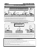
Seng up the pulse is not a process with a fixed ad-
justment procedure. Changes to frequency, balance,
and me will skew the nal result. A slow pulse with a
equal 50% pulse me on and somewhere around a
Basic Theory and Function Section 3