TO OUR CUSTOMER: Thank you for purchasing an EverRide Wasp Walk Behind Mower. We believe that you have exercised excellent judgment in your selection. The Wasp has been designed to give you many years of satisfactory service. Successful operation and long life depends on proper maintenance and correct operating techniques. Before you received your unit, the dealer has performed a pre-delivery inspection. The dealer will discuss with you the features, operation and maintenance requirements.
OWNER’S WARRANTY INFORMATION This warranty applies to the original retail purchaser of the EverRide products only. The warranty period starts upon the date of the original purchase reflected on the sales invoice. As a condition to this warranty, the owner/operator shall have read, understood and followed the operator’s manual guidelines for operations and maintenance supplied with this product, and that the product registration shall have been mailed to EverRide.
CONTENTS - 1 EverRide Wasp Operator’s & Parts Manual CONTENTS SAFETY 2 INTRODUCTION 3 IDENTIFICATION 4 MODEL/SERIAL NUMBERS 4 SPECIFICATIONS 5 ASSEMBLY INSTRUCTIONS 5 FINAL CHECK/ADJUSTMENT 6 BEFORE OPERATING 7 HEIGHT ADJUSTMENT 8 LUBRICATION/MAINTENANCE LUBRICATION MAINTENANCE 8 8 9 SAFETY DECALS 10 WIRING SCHEMATIC 11 TORQUE CHART 12 PARTS PAGES 14 32” FRONT DECK ASSEMBLY 14 36” FRONT DECK ASSEMBLY 18 48” FRONT DECK ASSEMBLY 22 REAR DECK ASSEMBLY 26 HANDLE ASSEMBLY 28
2 - IDENTIFICATION Your mower is only as safe as the operator! Operator carelessness or error may result in serious bodily injury. Improper maintenance of the machine may also result in injury. Please read and follow these instructions on Safe Operation and be certain that anyone using this mower fully understands and follows these instructions. 1. Familiarize yourself with the controls know how to stop this mower. and DANGER: WARNING: DO NOT allow children to operate the machine.
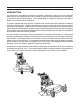
INTRODUCTION - 3 INTRODUCTION The information in this publication describes the operation, maintenance and servicing of the EverRide Wasp mowers. Every effort has been made to provide correct and concise information to you, the operator, as available at date of book publication. Your EverRide dealer is available should items in this book or details of your machine not be understood.
4 - IDENTIFICATION IDENTIFICATION Model / Serial Numbers The engine model number is found on a decal on the left side of the engine block on the oil reservoir next to the electric starter. The engine serial number is located at the bottom of the same decal. Each EverRide Wasp mower is identified by means of model and serial numbers.
SPECIFICATIONS/ASSEMBLY INSTRUCTIONS - 5 SPECIFICATIONS Belt Tension Guide Deflection Measured With 12 lbs. of Force Belt Inch Deflection How to Adjust Engine to Deck Transmission Belt Right Blade Drive Belt 1/2” 1/2” 1/2” (48”,52”, And 60” only) 1/2” Turnbuckle at Idler Sliding Idler Threaded Rod to Idler Wheel Drive Self-Adjusting Assembly Instructions 1. Remove inner parts box and handle from crate. Remove outside frame work so that the mower is setting on the pallet. 2.
6 - ASSEMBLY INSTRUCTIONS/FINAL CHECK/ADJUSTMENT Assembly Instructions 7. 8. Using drive rods provided, turn them into the 5/16” swivel located in the left and right hand idler engagement bracket. Adjust the rods so that there is approximately 1/4” to 3/8” between the rod and the bottom of the thumb latch. Rods should be locked in place by using 4 – hair pin cotters and by placing a 5/16” flat washer to be inside of the drive handle between the drive lever and hair pin cotter. (See fig.
BEFORE OPERATING - 7 Before Operating Know your machine top to bottom. Make certain all safety standards and instructions have been fully read and understood. Be acquainted with all “SAFETY INSTRUCTIONS” in this manual – to start. 1. Fill the fuel tank and open the fuel valve. 2. Shift the transmission to neutral. 3. Blades engagement lever must be in the “Off” position or back. 11. This unit is equipped with “Operator Presence Controls” on the upper handle.
8 - HEIGHT ADJUSTMENT/LUBRICATION / MAINTENANCE HEIGHT ADJUSTMENT REAR DECK MOUNT IN HIGHEST POSITION REAR DECK MOUNT IN LOWEST POSITION (5) spacers on top of caster arm (4) spacers on top of caster arm (3) spacers on top of caster arm (2) spacers on top of caster arm (1) spacer on top of caster arm All spacers under caster arm = = = = = = 1 7/8” to 3 1/8” 2 1/8” to 3 3/8” 2 1/2” to 3 3/4” 2 5/8” to 3 7/8” 2 7/8” to 4 1/8” 3 1/4” to 1 1/2” (5) spacers on top of caster arm = 1 1/2” to 2 3/4” (4) spacers
LUBRICATION / MAINTENANCE - 9 LUBRICATION / MAINTENANCE NOTE: The Peerless Transmission is “LIFETIME LUBRICATED”. If service is required, contact an authorized Peerless Dealer or Repair Center. MAINTENANCE 1. Engine: For complete maintenance and operating information for your engine, please refer to your engine operating and maintenance manual provided by the engine manufacturer. 2.
10 - SAFETY DECALS SAFETY DECALS DANGER TO AVOID SERIOUS INJURY FROM THROWN OBJECTS OR BLADE CONTACT DO NOT STAND NEAR MACHINE WHEN IN OPERATION DO NOT OPERATE MOWER WITHOUT GRASS DEFLECTOR OR GUARD IN PLACE 160173 160173 E36 30 38 E363023 E363233 WARNING Shield Missing. DO NOT Operate.
WIRING DIAGRAM - 11 PART #: E363371 WIRE HARNESS FOR WKW1332; 13 HP KAWASAKI WIRE HARNESS FOR WKW1536; 15 HP KAWASAKI WIRE HARNESS FOR WKW1548; 15 HP KAWASAKI REAR VIEW OF SAFETY MODULE CONN. 363372 A B C D E F 18 GA GREEN 18 GA BLACK 18 GA RED TO ENGINE KILL 18 GA BROWN 363208 OPC SWITCH 603060 ON/OFF KEY SWITCH 18 G A E HIT AW 18 G YELL OW N/O 363207 TRANS.NEUTRAL SWITCH N/C 18 GA VIOLET 18 GA YELLOW TO ENGINE GND.
12 - BOLT TORQUE CHART FASTENER TORQUES Mounting bolts and fasteners may tend to work loose during operation due to vibration or stress. A visual check of the complete mower should be made daily. All fasteners should be checked for correct retention torque, weekly, and more often if the unit is being operated in rough areas. All locally procured fastening hardware should be Grade 5 or equivalent. Use the following chart for general torque specifications for Grade 5 standard fasteners.
NOTES - 13
14 - 32” Front Deck Assembly 1 2 5 3 6 7 20 8 9 21 5 24 22 25 26 15 16 27 25 28 39 20 40 60 62 37 39 11 14 5 17 30 61 35 59 42 20 20 41 43 46 44 13 48 49 10 12 2 19 29 36 13 47 28 20 20 43 50 51 58 52 56 50 53 57 34* 63 18
32” Front Deck Assembly - 15 ITEM PART NO.
16 - 32” Front Deck Assembly 1 2 5 3 6 7 20 8 9 21 5 24 22 25 26 15 16 27 25 28 39 20 40 60 62 37 39 11 14 5 17 30 61 35 59 42 20 20 41 43 46 44 13 48 49 10 12 2 19 29 36 13 47 28 20 20 43 50 51 58 52 56 50 53 57 34* 63 18
32” Front Deck Assembly - 17 ITEM PART NO. QTY 43 44 45 46 47 48 49 50 51 52 53 56 57 58 59 60 61 62 63 960023 170120 E109014 E323029 960026 960046 170122 E363350 E363380 E583113 E583112 E363379 E363382 170135 E322019 E104511 960606 E105269 E583108 8 1 1 1 3 6 1 4 2 2 2 2 10 1 1 2 2 2 2 5/16" X 1" HEX BOLT ASSY, DECK 32 W/DECALS S/O SHOULDER BOLT SQUARE BUMPER 5/16" X 1 3/4" HEX BOLT 3/8" X 1" HEX BOLT ASSY, DEF.
18 - 36” Front Deck Assembly 1 2 5 3 6 7 20 8 9 21 5 24 22 25 26 27 25 15 16 60 29 20 40 5 17 30 36 38 62 37 61 35 59 42 20 20 41 43 47 28 43 46 44 13 48 49 11 14 2 19 28 39 13 10 12 20 20 20 50 51 58 52 56 50 53 57 34 63 18
36” Front Deck Assembly - 19 ITEM # PART NO.
20 - 36” Front Deck Assembly 1 2 5 3 6 7 20 8 9 21 5 24 22 25 26 27 25 15 16 60 29 20 40 5 17 30 36 38 62 37 61 35 59 42 20 20 41 43 47 28 43 46 44 13 48 49 11 14 2 19 28 39 13 10 12 20 20 20 50 51 58 52 56 50 53 57 34 63 18
36” Front Deck Assembly - 21 ITEM # PART NO. QTY 41 42 43 44 45 46 47 48 49 50 51 52 53 56 57 58 59 60 61 62 63 960603 960024 960023 170125 E109014 E363304 960026 960046 170122 E363350 E363380 E583113 E583112 E363379 E363382 170141 E322019 E104511 960606 E105269 E583108 6 8 8 1 1 1 3 6 1 4 2 2 2 2 10 1 1 2 2 2 2 7/16" LOCK WASHER 5/16" X 1 1/4" HEX BOLT 5/16" X 1" HEX BOLT ASSY, DECK 36 W/DECALS S/O SHOULDER BOLT SQUARE BUMPER 5/16" X 1 3/4" HEX BOLT 3/8" X 1" HEX BOLT ASSY, DEF.
22 - 48” Front Deck Assembly 1 2 5 4 6 7 8 20 5 21 12 23 13 24 25 66 48 20 52 14 15 65 35 2 65 19 26 27 27 26 55 33 31 35 49 20 50 20 64 13 47 43 20 45 42 20 20 20 46 26 54 56 20 57 58 61 53 51 45 45 44 5 24 34 32 39 40 22 41 29 16 17 30 24 38 2 23 24 37 36 35 2 28 9 10 11 56 59 60 62* 63 18
48” Front Deck Assembly - 23 ITEM # PART NO.
24 - 48” Front Deck Assembly 1 2 5 4 6 7 8 20 5 21 12 23 13 24 25 66 48 20 52 14 15 65 35 2 65 19 26 27 27 26 55 33 31 35 49 20 50 20 64 13 47 43 20 45 42 20 20 20 46 26 54 56 20 57 58 61 53 51 45 45 44 5 24 34 32 39 40 22 41 29 16 17 30 24 38 2 23 24 37 36 35 2 28 9 10 11 56 59 60 62* 63 18
48” Front Deck Assembly - 25 ITEM # PART NO.
26 - Rear Deck Assembly 58 50 59 54 13 50 57 52 7 16 13 51 15 14 11 56 29 12 3 49 31 33 34 9 2 55 32 8 41 48 29 10 5 4 29 62 6 60 10 9 3 6 2 2 3 94 0 1 0 31 64 65 66 16 30 35 29 67 63 38 37 20 1 19 24 22 21 17 42 44 43 45 31 23 27 18 47 25 23 26 28 46 61
Rear Deck Assembly - 27 ITEM # PART NO.
28 - Rear Deck Assembly 58 50 59 54 13 50 57 52 7 16 13 51 15 14 11 56 29 12 3 49 31 33 34 9 2 55 32 8 41 48 29 10 5 4 29 62 6 60 10 9 3 6 2 2 3 94 0 1 0 31 64 65 66 16 30 35 29 67 63 38 37 20 1 19 24 22 21 17 42 44 43 45 31 23 27 18 47 25 23 26 28 46 61
Rear Deck Assembly - 29 ITEM # PART NO. QTY 37 38 39 40 41 42 43 44 45 46 47 48 49 50 51 52 54A 54B 55 56 57 58 59 60 61 E362031 E482003 E363169 960702 E363220 E107262 E363119 E363124 E363216 E363215 E363212 960022 E523320 E363165 E363029 E363142 E362041 E362042 E363177 E363135 E108500 E362026 960050 E363176 960001 1 1 1 1 1 1 1 1 1 1 1 4 1 4 4 1 1 1 4 2 2 2 2 2 8 DESCRIPTION BELT GUIDE BRKT (32" AND 36") BELT GUIDE BRKT (48") SMALL IDLER 3/8" STD FLAT WASHER TRANSMISSION SHEAVE KEY 1/4" SQ.
30 - Handle Assembly 12 15 16 15 14 10 8 9 45 7 13 10 11 9 15 36 5 43 6 35 49 50 26 46 90 4 49 2 27 28 34 37 24 3 21 44 47 53 54 38 23 30 83 17 51 42 40 33 61 20 48 55 25 31 18 19 59 39 29 32 27 57 58 60 9 81 81 82 88 65 38 66 20 60 7 84 85 56 78 56 9 79 41 80 72 77 70 89 67 69 73 76 67 75 71 70 52 64 1 47 74 39 91 67 67 68 62 61 63
Handle Assembly - 31 ITEM # PART NO.
32 - Handle Assembly 12 15 16 15 14 10 8 9 45 7 13 10 11 9 15 36 5 43 6 35 49 50 26 46 90 4 49 2 27 28 34 37 24 3 21 44 47 53 54 38 23 30 83 17 51 42 40 33 61 20 48 55 25 31 18 19 59 39 29 32 27 57 58 60 9 81 81 82 88 65 38 66 20 60 7 84 85 56 78 56 9 79 41 80 72 77 70 89 67 69 73 76 67 75 71 70 52 64 1 47 74 39 91 67 67 68 62 61 63
Handle Assembly - 33 ITEM # PART NO.
34 - Handle Assembly 12 15 16 15 14 10 8 9 45 7 13 10 11 9 15 36 5 43 6 35 49 50 26 46 90 4 49 2 27 28 34 37 24 3 21 44 47 53 54 38 23 30 83 17 51 42 40 33 61 20 48 55 25 31 18 19 59 39 29 32 27 57 58 60 9 81 81 82 88 65 38 66 20 60 7 84 85 56 78 56 9 79 41 80 72 77 70 89 67 69 73 76 67 75 71 70 52 64 1 47 74 39 91 67 67 68 62 61 63
Handle Assembly - 35 ITEM # PART NO. QTY 74 75 76 77 78 79 80 81 82 83 84 85A 85B 85C 88 89 90 91 92 E363368 E104761 E363370 E583194 170128 963095 E363201 E101295 E363352 E363159 E363128 E104251 960702 E363226 E362060 E363355 E363372 105684 E492025 2 1 1 1 1 4 2 3 1 2 1 1 1 1 1 1 1 1 1 DESCRIPTION FUEL TANK BELT LEFT HAND NUT O-RING FUEL CAP ASSY, SHIFT GUIDE W/DECAL S/O 1/4" X 3/4" CARRIAGE BOLT FUEL TANK PAD #10 X 1 1/2" SLTD. MACH.
36 - Caster Assembly 1 5 3 4 5 1 7 6 2 13 8 9 10 11 9 10 12 14 15
Caster Assembly - 37 ITEM # PART NO.
38 - Belt Drive Walk Behind Decals DANGER WARNING TO AVOID SERIOUS INJURY FROM THROWN OBJECTS OR BLADE CONTACT DO NOT STAND NEAR MACHINE WHEN IN OPERATION DO NOT OPERATE MOWER WITHOUT GRASS DEFLECTOR OR GUARD IN PLACE Shield Missing. DO NOT Operate.
Belt Drive Walk Behind Decals - 39 ITEM # PART NO. QTY 1 2 3 4 5 6 7 8 9 10 11 12 13 14 15 16 17 160173 160169 170134 170138 170145 170146 181000 191369 E363037 E363039 E363289 E363038 E363023 E523018 E363364 E363241 E363233 1 1 1 1 2 1 1 1 1 1 2 1 2 1 1 1 1 DESCRIPTION Decal, Danger Chute Decal, Shield Missing Decal, 32 Decal, 36 DECAL, WASP Decal, EverRide Decal, EverRide 11" Decal, 48 Cutter Blade Label Throttle Decal Neutral Park Decal Caution/Instr.
40 - PARTS LIST PART NO. PAGE ITEM PART NO. PAGE ITEM PART NO.
PARTS LIST - 41 PART NO. PAGE ITEM PART NO. PAGE ITEM PART NO.
42 - PARTS LIST PART NO. PAGE ITEM PART NO. PAGE ITEM PART NO.
PARTS LIST - 43 PART NO.
44 - NOTES 170147 8/05