WASP Owner/Operator Manual Manuel Du Propriétaire/Utilisateur Models 988410 - EGWKA1332S 988411 - EGWKA1336S 988412 - EGWKA1548S ENGLISH FRANÇAIS 03823902 1/09 Printed in USA
TABLE OF CONTENTS Safety . . . . . . . . . . . . . . . . . . . . . . . . . . . . . . . . . . . . . . 3 Service and Adjustments . . . . . . . . . . . . . . . . . . . . . 18 Assembly . . . . . . . . . . . . . . . . . . . . . . . . . . . . . . . . . . . 9 Storage . . . . . . . . . . . . . . . . . . . . . . . . . . . . . . . . . . . . 26 Controls and Features. . . . . . . . . . . . . . . . . . . . . . . . 10 Troubleshooting . . . . . . . . . . . . . . . . . . . . . . . . . . . . 27 Operation . . . . . . .
PRODUCT REGISTRATION DISCLAIMER The dealer must register the product at the time of purchase. Registering the product will help the company process warranty claims or contact you with the latest service information. All claims meeting requirements during the limited warranty period will be honored, whether or not the product registration card is returned. Keep a proof of purchase if you do not register your unit.
NOTATIONS 1. Danger! To avoid serious injury or death NOTE: General reference information for proper operation and maintenance practices. Read the operator’s manual. IMPORTANT: Specific procedures or information required to prevent damage to unit or attachment. OL1801 PRACTICES AND LAWS Keep children and others away from unit while operating. Practice usual and customary safe working precautions, for the benefit of yourself and others. Understand and follow all safety messages.
b. Never remove gas cap or add fuel when engine is running. Do not smoke. 3. Warning! ( c. Never refuel or drain the machine indoors. Always stand clear of discharge. • OL0910 DO NOT operate mower unless guards are in operating position or bagger is attached. Check that the operator’s presence controls, safety switches and shields are attached and functioning properly. Do not operate unless they are functioning properly.
• Be aware of the mower discharge direction and do not point it at anyone. • Do not operate the machine while under the influence of alcohol or drugs. • Use care when loading or unloading the machine into or off of a trailer or truck. • Use care when approaching blind corners, shrubs, trees, or other objects that may obscure vision. • Inspect machine before you operate. Be sure hardware is tight. Repair or replace damaged, badly worn, or missing parts.
• Keep hands, feet and clothing away from mower deck when engine is running. • Be alert at all times, drive forward carefully. People, especially children can move quickly into the mowing area before you know it. • Always wear safety goggles, or safety glasses with side shields, and a hard hat when operating the machine. • Wear close fitting clothing and safety equipment appropriate for the job.
• Keep all parts in good working condition and all hardware tightened. Replace all worn or damaged decals. • Check grasscatcher components and the discharge guard frequently and replace with manufacturer’s recommended parts, when necessary. Grasscatcher components are subject to wear, damage, and deterioration which could expose moving parts or allow objects to be thrown. • Keep all nuts and bolts tight, especially blade attachment bolts, to be sure the equipment is in safe working condition.
• Never store the machine or fuel container where there is an open flame, spark, or pilot light such as on a water heater or other appliance. • Prevent fire and explosion caused by static electric discharge. Static electric discharge can ignite fuel vapors in an ungrounded fuel container. • Never fill containers inside a vehicle or on a truck or trailer bed with a plastic liner. Always place containers on the ground away from your vehicle before fueling.
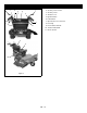
CONTROLS AND FEATURES 7 2 11 6 4 1. Shift Lever 7 2. Steering Lever Latches 3. Steering Levers 2 4. Throttle Lever 5. Ignition Switch 6. PTO Switch 3 7. Operator Presence Controls 3 8. Fuel Cap 1 5 9. Recoil Starter Handle 10. Traction Belt Guard 11.
OPERATION Steering Levers WARNING: AVOID INJURY. Read and understand the entire Safety section before proceeding. WARNING: AVOID INJURY. When the engine is running and the shift lever is engaged, releasing only one steering latch causes the unit to circle around one drive wheel. CONTROLS AND FEATURES ALWAYS hold both steering levers against the handlebar when releasing the steering lever latches. ALWAYS release levers slowly. See Figure 3 for controls and features locations.
Fuel is blended to give best seasonal performance. To avoid engine performance problems such as hard starting or vapor lock, use in-season fuel. Use fuel during warm weather that was purchased during that season, and use fuel during cold weather that was purchased during that season. Shift Lever The shift lever sets the direction and speed of the unit.
7. Let the rope rewind slowly. WARNING: AVOID INJURY. When the engine is running and the shift lever is engaged, releasing only one steering latch causes the unit to circle around one drive wheel. 8. Pull rope with rapid continuous full arm stroke to start engine. Allow rope to rewind slowly. IMPORTANT: DO NOT let starter handle snap against engine. ALWAYS hold both steering levers against the handlebar when releasing the steering lever latches. ALWAYS release levers slowly. 9.
To mow: Top Mounting Holes 1. Lock steering levers in neutral. 2. Put the shift lever in neutral. 3. Move the throttle lever to the fast position. 4. Engage the operator presence control lever. NOTE: Operator presence control must remain engaged. 5. Move the PTO switch to On to engage mower. IMPORTANT: NEVER engage the PTO if the mower is plugged with grass or other material. This will damage the PTO belt. 6. Move the shift lever to set a slow ground speed. 7.
Store unused 1/4" blade spacers here when not in use. WARNING: Sharp edges can cut. Moving parts can cut off fingers or a hand. Wrap blade(s), wear sturdy gloves and use extreme caution when servicing. On multi-blade mowers, rotation of one blade will cause all blades to rotate. 8. Remove the mower blade from the spindle and place the appropriate number of 1/4" spacers between the spindle and the blade. IMPORTANT: DO NOT allow the blade to be less than 3.2mm (1/8 in.) above the lip of the mower deck. 9.
CUTTING HEIGHT CHART – DECK BOLTED TO FRAME WITH BOTTOM HOLES Approximate Cutting Height 1/4" Blade Spacers 1/2" Castor Spacers cm (Inches) Stored Below Weldment 0 1 2 3 7.62 (3.0) 8.3 (3.25) 8.9 (3.5) 9.5 (3.75) 8.3 (3.25) 8.9 (3.5) 9.5 (3.75) 0 1 2 3 0 1 2 10.2 (4.0) 8.9 (3.5) 9.5 (3.75) 10.2 (4.0) 10.8 (4.25) 3 0 1 2 3 Above Weldment 3 3 3 3 3 3 3 3 3 2 1 0 3 2 1 4 4 4 4 5 5 5 2 2 2 2 1 1 1 0 3 2 1 0 5 6 6 6 6 1 0 0 0 0 PARKING 1. Shut off the unit.
MAINTENANCE SCHEDULE Period Service Check Safety Interlock System Every 50 Hours Every 100 Hours WARNING: Safety interlock system failure and improper operation of unit can result in death or serious injury. Test this system each time the unit is operated. If this system does not function as described, do not operate until repairs are made. See Check Safety Interlock System on page 11. Check Air Cleaner Check the air cleaner element before each use. See engine manual for detailed instructions.
SERVICE AND ADJUSTMENTS If unit turns to the left: 1. Reduce the air pressure in the right tire. WARNING: AVOID INJURY. Read and understand the entire Safety section before proceeding. 2. Increase the air pressure in the left tire. 3. Check for brake binding on left wheel and adjust as needed. GENERAL LUBRICATION Apply a small amount of oil to the pivot points as required for smooth operation (Figure 8). Apply high quality lithium based grease to all lube fittings every 50 hours of operation.
ADJUST BRAKES WARNING: AVOID INJURY. An extension spring, when extended, stores energy and can be dangerous. Always use tools specifically designed for installing or removing an extension spring. Always compress or extend springs slowly. NOTE: The traction belt must disengage as the brake starts to engage. 1. Turn off the engine, remove the key and allow unit to cool. 2. If brakes do not disengage fully when traction belt is engaged, the brakes are too tight.
To adjust: NOTE: Move spring anchor location to hole to gain more traction on hilly terrain. 1. Stop the engine. Remove ignition key. Put PTO lever in the "OFF" position. Put the shift lever in neutral. 2. Loosen two 5/16-18 bolts on shift lever. 3. Align the shift lever so it is centered in gear position 2 on the detent plate and is .8mm (.030 in.) from the V (Figure 14).
32" and 36" BELT REPLACEMENT 6. Install new transmission belt in the top groove of the clutch hub and on the transmission sheave. 7. Slide idler pulley to the belt to tension it, and then tighten the mounting bolt to hold the position. (Figure 15). 1 2 3 8. Reposition clutch stop, replace engine bolt, and torque both engine bolts to 23 N•m (17 lbf-ft). 3 9. Reinstall mower drive belt on mower clutch sheave. 1 2 6 5 3 5 4 6 1. Belt 2. Idler Spring 3. Deck Sheave 4 7 5 6 1. Transmission Belt 2.
MOWER BLADES 6. Tighten the adjusting nut to tension the belt. Tighten the nut until the idler spring compresses to 5.1cm +/– 0.32cm (2 in. +/– 1/8 in.). See Figure 17. NOTE: If mower is used under sandy soil conditions, replace blades when air lifts become eroded through at ends (Figure 18). 7. Replace deck cover. Mower Drive Belt DO NOT sharpen to this pattern NOTE: Deck belt must be removed before removing the mower drive belt. 1. Stop engine, remove key and wait for all hot parts to cool. 2.
Replacing Mower Spindle Bearings 32" and 36" Decks 1. Turn the engine off. Remove the ignition key. Remove the ignition wire from the spark plugs. 2. Remove mower blade. 3. Remove nut, flat washer, spacer and pulley. 4. Remove spindle shaft, lower bearing and spacer from spindle housing. Discard bearing. 5. Remove and discard upper bearing. 1 6. Clean entire assembly. 7. Install a new lower bearing and spacer on the spindle shaft.
4. Remove pulleys: Replacing Mower Spindle Bearings - 48-Inch Mower Deck • Left Spindle: Remove nut, flat washer and pulley. 1. Turn the engine off. Remove the ignition key. Remove the ignition wire from the spark plugs. • Center Spindle: Remove nut, drive pulley and spindle pulley. 2. Remove engine-to-deck drive and spindle drive belts. • Right Spindle: Remove nut, flat washer pulley and spacer. 3. Remove mower blades. 5. Remove spindle shaft, lower bearing and spacer from spindle housing.
NOTE: Do not remove the caster yoke from the deck to replace the bearings and bushings. Service Electrical 1 Replace Fuse 2 IMPORTANT: Avoid damage! When replacing fuses use only 25-amp fuses or you may damage the circuit. The machine is equipped with one 25-amp fuse to protect the charging circuit. This fuse is located on the main harness, near the engine ground. 1. Remove defective fuse from socket. 3 2. Check metal clip in fuse window and discard fuse if clip is broken. 3.
SERVICE PARTS STORAGE 07200502 1 Mower Deck Belt (32-in. Deck) 00201010 1 Mower Deck Belt (36-in. Deck) D38019 1 Mower Deck Belt (48-in. Deck) Check each item in the MAINTENANCE SCHEDULE on page 17, but do not add gasoline. 07200504 1 Deck Drive Belt (48-in. Deck) Clean the unit. Touch up all scratched painted surfaces. 07243600 2 Traction Drive Belt IMPORTANT: Never spray unit with high-pressure water or store unit outdoors. Store unit in a cool, dry, protected location.
TROUBLESHOOTING PROBLEM Engine will not start PROBABLE CAUSE CORRECTION 1. The engine will not start unless the shift lever is in neutral, the key is in the On position, and the Power Take Off (PTO) is Off. 1. Safety Interlock System is preventing start. 2. Fuel tank is empty or fuel is contaminated. 3. Air cleaner is clogged or damaged. 2. Add fuel. If necessary, replace the fuel with clean, fresh fuel. 3. Clean or replace the filter element. See engine manual. 4.
SPECIFICATIONS Model Number Model 988410 988411 988412 EGWKA1332S EGWKA1336S EGWKA1548S Engine Engine Engine Model Number Kawasaki FH381V FH381V Governed RPM (May be different from maximum RPM) 3600 ± 100 Cooling Capacity Air Cooled FH430V Speed Forward Maximum – mph (km/h) 5.4 (8.
Two-Year Limited EverRide® Warranty ® Ariens Company (Ariens) warrants to the original purchaser that EverRide brand products manufactured by Ariens, designated or labeled commercial products by Ariens, and sold after December 31, 2007 will be free from defects in material and workmanship for a period of two years after the date of purchase or 1000 hours of use, whichever comes first.
To find an EverRide authorized service representative, contact Ariens at: 655 W. Ryan Street Brillion, WI 54110 (920) 756 - 2141 www.everride.com Limitations • Batteries are warranted only for a period of 12 months after date of purchase, on a prorated basis. For the first 90 days of the warranty period, a defective battery will be replaced free of charge.
EverRide An Ariens Company 655 West Ryan Street Brillion, WI 54110-1072 920-756-2141 Fax 920-756-2407 www.everride.