ASME A112.18.1-2018/ CSA B125.
ASME A112.18.1-2018/CSA B125.1-18 Plumbing supply fittings Contents ASME A112 Standards Committee on Plumbing Materials and Equipment ASME A112.18.1 Project Team on Plumbing Fixture Fittings CSA Technical Committee on Plumbing Fixtures 1 Scope 8 11 CSA/ASME Harmonization Task Group on Plumbing Fixtures Preface 4 16 18 20 2 Reference publications 21 3 Definitions and abbreviations 3.1 Definitions 24 3.2 Abbreviations 28 24 4 Design requirements 29 4.1 Supply fittings 29 4.1.
ASME A112.18.1-2018/CSA B125.1-18 5.1 5.1.1 5.1.2 5.1.3 5.1.4 5.2 5.2.1 5.2.2 5.2.3 5.2.4 5.3 5.3.1 5.3.2 5.3.3 5.3.4 5.3.5 5.3.6 5.3.7 5.3.8 5.4 5.4.1 5.4.2 5.4.3 5.5 5.6 5.6.1 5.6.2 5.6.3 5.7 5.7.1 5.7.2 5.8 5.8.1 5.8.2 5.8.3 5.9 5.9.1 5.9.2 5.9.3 5.10 5.10.1 5.10.2 5.11 5.11.1 5.11.2 5.12 5.12.1 5.12.2 5.12.
ASME A112.18.1-2018/CSA B125.1-18 5.12.4 5.13 5.13.1 5.13.2 5.13.3 Plumbing supply fittings Spray coverage 57 High-efficiency commercial pre-rinse spray valves General 58 Flow rate 58 Spray force 59 58 6 Markings, packaging, and installation instructions 59 6.1 General 59 6.2 Temperature identification 59 6.3 Packaging 60 6.
ASME A112.18.1-2018/CSA B125.1-18 Plumbing supply fittings Preface This is the fourth edition of ASME A112.18.1/CSA B125.1, Plumbing supply fittings. It supersedes the previous edition published in 2012. Together with ASME A112.18.2/CSA B125.2, Plumbing waste fittings, CSA B125.3, Plumbing fittings, and ASME A112.18.6/CSA B125.6, Flexible water connectors, this Standard forms a series to cover plumbing fittings.
ASME A112.18.1-2018/CSA B125.1-18 Plumbing supply fittings situation. The inquirer may also include any plans or drawings, which are necessary to explain the question; however, they should not contain proprietary names or information. ASME procedures provide for reconsideration of any interpretation when or if additional information that might affect an interpretation is available. Further, persons aggrieved by an interpretation may appeal to the cognizant ASME Committee.
ASME A112.18.1-2018/CSA B125.1-18 Plumbing supply fittings ASME A112.18.1-2018/CSA B125.1-18 Plumbing supply fittings 1 Scope 1.
ASME A112.18.1-2018/CSA B125.1-18 Plumbing supply fittings Annexes are designated normative (mandatory) or informative (non-mandatory) to define their application. 1.5 SI units are the units of record in Canada. In this Standard, the inch/pound units are shown in parentheses. The values stated in each measurement system are equivalent in application; however, each system is to be used independently. Combining values from the two measurement systems can result in nonconformance with this Standard.
ASME A112.18.1-2018/CSA B125.1-18 Plumbing supply fittings B16.26-2006 Cast Copper Alloy Fittings for Flared Copper Tubes PTC 19.2-1987 (R2004) Pressure Measurement PTC 19.5-2004 Flow Measurement CSA Group CAN/CSA-B64 Series-11 Backflow preventers and vacuum breakers B125.3-12 Plumbing fittings C22.2 No. 14-13 Industrial control equipment C22.2 No. 24-15 Temperature-indicating and regulating equipment C22.2 No. 68-09 (R2014) Motor-operated appliances (household and commercial) C22.2 No. 94.
ASME A112.18.1-2018/CSA B125.
ASME A112.18.1-2018/CSA B125.1-18 Plumbing supply fittings NSF/ANSI 372-2016 Drinking Water System Components — Lead content SAE International (Society of Automotive Engineers) J512 (1997) Automotive Tube Fittings UL (Underwriters Laboratories Inc.
ASME A112.18.1-2018/CSA B125.1-18 Plumbing supply fittings Automatic compensating valve — a water-mixing valve that is supplied with hot and cold water and that provides a means of automatically maintaining the water temperature selected for an outlet. Note: Automatic compensating valves are used to reduce the risk of scalding and thermal shock. Backflow — a flowing back or reversal of the normal direction of flow. Note: Back siphonage and back pressure are types of backflow.
ASME A112.18.1-2018/CSA B125.1-18 Plumbing supply fittings Faucet — a terminal fitting. Lawn faucet — a faucet designed to be installed horizontally on the outside wall of a building with male or female IPS threads or copper solder connections on the inlet and hose threads on the outlet. Notes: 1) Lawn faucets can be frostproof. 2) The outlet is usually angled 45° from the horizontal. Lawn faucets include a flange that mounts flush with the wall.
ASME A112.18.1-2018/CSA B125.1-18 Plumbing supply fittings Operating control — a part of a supply fitting or accessory that manually controls the temperature, direction, or flow rate of water or that closes and opens the water supply. Outlet — Primary outlet — the outlet from a supply fitting on the discharge side of a valve through which water will discharge unless diverted to a secondary outlet.
ASME A112.18.1-2018/CSA B125.1-18 Plumbing supply fittings Rain shower — a showerhead designed to be mounted directly over the bather with the spray face parallel to the floor. Note: The showerhead can be mounted directly from the ceiling or on an extended shower arm. Significant surface — an exposed surface that, if blemished, spoils the appearance or affects the performance of a fitting. Standard tools — tools that are normally carried by plumbers for installing and maintaining plumbing.
ASME A112.18.1-2018/CSA B125.1-18 Plumbing supply fittings 4 Design requirements 4.1 Supply fittings 4.1.1 Rated pressure 4.1.1.1 Supply fittings shall be designed for a rated supply pressure of 690 kPa (100 psi). 4.1.1.2 Supply fittings shall be designed to function at a supply pressure between 140 and 860 kPa (20 and 125 psi). 4.1.2 Rated temperatures 4.1.2.1 Supply fittings shall be designed for rated supply temperatures from 5 to 71 °C (40 to 160 °F). 4.1.2.
ASME A112.18.1-2018/CSA B125.1-18 Plumbing supply fittings 4.2 Servicing Supply fittings, excluding supply stops, shall be designed so that replacement of wearing parts can be accomplished a) without removing the fitting from the supply system; b) without removing the piping from the body; c) without disturbing the finished wall; and d) using standard tools or manufacturer-provided tools.
ASME A112.18.1-2018/CSA B125.1-18 Plumbing supply fittings Inlets and shanks may be designed to mate with other common connections. Note: Longer shank lengths are sometimes necessary on account of fitting orientations and countertop thickness or materials. 4.4.8 Alternative end-threaded connections for flexible hoses and flexible components shall comply with the performance requirements of this Standard. 4.4.
ASME A112.18.1-2018/CSA B125.1-18 Plumbing supply fittings 4.8 Cover plates and escutcheons 4.8.1 The cover plates of deck-mounted lavatory and sink supply fittings shall have the dimensions indicated in Figure 1, except as specified in Clause 4.8.2. Note: Refer to the appropriate fixture standards for the minimum mounting surface dimensions. 4.8.
ASME A112.18.1-2018/CSA B125.1-18 c) Plumbing supply fittings at least one of the modes shall comply with the requirements specified in Clauses 5.12.2.2.2, 5.12.3, and 5.12.4 for high efficiency. The manufacturer shall indicate which mode is to be tested for high efficiency. 4.11.2.2 See Clause 6.4 for additional marking requirements for high-efficiency showerheads and hand-held showers. 4.12 Cross-flow 4.12.1 Except as otherwise allowed by Clause 4.12.
ASME A112.18.1-2018/CSA B125.1-18 Plumbing supply fittings 4.13.2 Testing When used with a plumbing fitting, electrical plumbing controls, including solenoid valves, shall a) be considered components of the plumbing fitting; b) be tested with the fitting; and c) comply with Clause 5.6. Replacement of a battery during the life cycle testing specified in Clause 5.6 shall not be considered a failure. 4.
ASME A112.18.1-2018/CSA B125.1-18 Plumbing supply fittings 5 Performance requirements and test procedures 5.1 General 5.1.1 Preconditioning Before testing, specimens shall be conditioned at ambient laboratory conditions for not less than 12 h. 5.1.2 Installation for testing For test purposes, specimens shall be installed in accordance with the manufacturer’s instructions. 5.1.3 Test conditions Unless otherwise specified in this Standard, tests shall be conducted at ambient laboratory conditions. 5.1.
ASME A112.18.1-2018/CSA B125.1-18 d) Plumbing supply fittings ASTM B380 (Corrodkote): this test shall be applicable to SC-2 devices and shall have a duration of 4 h. Note: If more than one test method is specified, the manufacturer may specify which method is to be used. SC-1 and SC-2 are defined in Clause 3.1. 5.2.2.2.2 An SC-1 specimen that passes the SC-2 test shall be considered to have met the requirements of Clause 5.2.2.2.1. 5.2.3 Adhesion 5.2.3.
ASME A112.18.1-2018/CSA B125.1-18 Plumbing supply fittings Under dry conditions, the specimens shall be subjected consecutively to four complete cycles of temperatures, with each complete cycle consisting of the following steps in the following order: a) – 40 ± 2 °C (– 40 ± 4 °F) for 20 min to 1 h; b) 20 ± 5 °C (68 ± 9 °F) for a minimum of 20 min; c) 75 ± 2 °C (167 ± 4 °F) for 20 min to 1 h; and d) 20 ± 5 °C (68 ± 9 °F) for a minimum of 20 min.
ASME A112.18.1-2018/CSA B125.1-18 Plumbing supply fittings 5.3 Pressure and temperature 5.3.1 Static and dynamic seals 5.3.1.1 Failure criteria Seals of plumbing supply fittings and accessories, except those of automatic compensating valves (see Clause 4.15), shall not leak or otherwise fail when tested in accordance with Clauses 5.3.1.2 to 5.3.1.4. 5.3.1.2 Procedure with the valve closed The specimen shall be tested in accordance with Clause 5.3.1.
ASME A112.18.1-2018/CSA B125.1-18 Plumbing supply fittings 5.3.2.3 Line fittings Line fittings shall withstand a hydrostatic pressure of 3450 kPa (500 psi) for 1 min. The pressure shall be applied to the inlet with the outlet blocked and the valve open. 5.3.3 Cross-flow check valves Note: See Clause 4.12 for additional cross-flow requirements. 5.3.3.1 Performance requirements When tested in accordance with Clauses 5.3.3.2 and 5.3.3.3, cross-flow check valves shall not leak more than 35 mL/min (0.
ASME A112.18.1-2018/CSA B125.1-18 Plumbing supply fittings 5.3.6 Diverters 5.3.6.1 Bath and shower 5.3.6.1.1 When tested in accordance with Clause 5.3.6.1.2, the rate of the leakage from a primary outlet when flow is through the secondary outlet shall not exceed 400 mL/min (0.1 gpm). 5.3.6.1.
ASME A112.18.1-2018/CSA B125.1-18 Plumbing supply fittings 5.4 Flow rate 5.4.1 Supply fittings Fittings and accessories shall meet the minimum and maximum flow rate requirements specified in Table 1, at the temperatures and flowing pressures specified in Clause 5.4.2.3, with the exception of high-efficiency commercial pre-rinse spray valves, which shall be tested in accordance with Clause 5.4.3. These requirements shall be met before and after the life cycle tests specified in Clause 5.6. 5.4.
ASME A112.18.1-2018/CSA B125.1-18 c) Plumbing supply fittings for maximum flow for low-pressure water dispensers: at 105 kPa ± 7 kPa (15 psi ± 1 psi) at the inlet when water is flowing. 5.4.2.3.2 Flow rate tests for showerheads, body sprays, and hand-held showers shall be conducted with water at 38 ± 6 °C (100 ± 10 °F) and the flow maintained for at least 1 min.
ASME A112.18.1-2018/CSA B125.1-18 Plumbing supply fittings be tested at both water temperatures. Operating controls shall not require a moving force greater than 45 N (10 lbf) or 22 N (5 lbf) for accessible designs. 5.5.4 Swing spouts, including those with pullout spouts, shall be tested at a flowing pressure of 860 ± 14 kPa (125 ± 2 psi), with water at 10 ± 6 °C (50 ± 10 °F). The force required to turn the spouts shall not exceed 45 N (10 lbf) measured at the end of the spout. 5.5.
ASME A112.18.1-2018/CSA B125.1-18 b) c) Plumbing supply fittings may have the spout nut tightened once during the test to stop leakage; and shall not require a turning force greater than 45 N (10 lbf) at the end of the spout when the flowing pressure is 860 kPa (125 psi) and the water temperature is 10 ± 6 °C (50 ± 10 °F). 5.6.1.3.2 Swing spouts with pullout spouts shall not require a turning force greater than 45 N (10 lbf) at the end of the spout. 5.6.1.
ASME A112.18.1-2018/CSA B125.1-18 Plumbing supply fittings 5.6.2.2 General parameters 5.6.2.2.1 The speed of the life cycle test apparatus shall be adjusted to 1500 ± 150 cycles of operation per hour unless otherwise specified in this Standard or by the manufacturer. 5.6.2.2.2 Water at a flowing pressure of 345 ± 35 kPa (50 ± 5 psi) and a supply pressure of 550 kPa (80 psi) maximum (valve closed) shall be supplied to the specimen throughout the test.
ASME A112.18.1-2018/CSA B125.1-18 Plumbing supply fittings 5.6.3.1.2 For single-control mixing valves or mixing valves with separate volume and temperature controls, the apparatus shall be adjusted to operate the valve as follows: a) For the volume cycle, the volume control shall be moved from the fully closed position to 80% (minimum) of the fully open position, without making contact with the end stops, and back to the fully closed position.
ASME A112.18.1-2018/CSA B125.1-18 b) c) d) e) f) Plumbing supply fittings multi-function aerators; shampoo diverters; showerhead adjustment mechanisms; showerhead flow or function controls; and side spray flow or function controls. 5.6.3.3.2 The following devices shall be tested at a flowing pressure of 345 ± 35 kPa (50 ± 5 psi) at 9.5 ± 0.4 L/min (2.5 ± 0.1 gpm) through a fixed outlet or with their standard accessories installed, when installed at a maximum distance of 2.
ASME A112.18.1-2018/CSA B125.1-18 Plumbing supply fittings The hot and cold water temperatures and the water pressures shall be those specified in Clause 5.6.2.2.2. 5.6.3.5 Shower hoses, pullout spout hoses, and side spray hoses 5.6.3.5.1 Hoses shall be subjected to a 67 N (15 lbf) tension test for 10 000 cycles, with the force applied gradually at the end of the hose connector. 5.6.3.5.
ASME A112.18.1-2018/CSA B125.1-18 Plumbing supply fittings 5.7.2.3 In addition to complying with the requirements specified in Clause 5.7.2.2, threaded supply connections shall comply with Clause 5.3.2. 5.7.2.4 Clauses 5.7.2.1 to 5.7.2.3 shall not apply to factory-assembled connections. 5.8 Resistance to use loading 5.8.1 Operating controls 5.8.1.
ASME A112.18.1-2018/CSA B125.1-18 Plumbing supply fittings 5.9 Backflow prevention 5.9.1 General Fittings shall be tested in accordance with the applicable tests specified in Clauses 5.9.2 and 5.9.3 and then retested within 48 to 96 h of completing all applicable life cycle tests specified in Clause 5.6. 5.9.2 Fittings with plain outlets 5.9.2.1 Air gaps Fittings with plain outlets shall be protected by an air gap in accordance with ASME A112.1.2 or A112.1.3.
ASME A112.18.1-2018/CSA B125.1-18 Plumbing supply fittings m) At the level specified in Item k), measure and record the distance between the lowest point of the outlet of the specimen and the water surface. The greater of the distances determined in Items h) and m) shall be the critical air gap of the fitting. The critical air gap test shall be repeated twice to confirm the critical air gap measurement. The critical level mark on the fittings (see Clause 5.9.2.
ASME A112.18.1-2018/CSA B125.1-18 b) c) Plumbing supply fittings a vacuum system that can maintain a 0 to 85 kPa (0 to 12 psi) vacuum; and the atmosphere. The coloured-water reservoir shown in Figure 5 shall be located below the mounting surface level of the specimen. The coloured water in the reservoir shall be at the mounting surface level. The terminal end of the sight tube shall be immersed 13 mm (0.5 in) below the mounting surface level of the coloured water in the reservoir.
ASME A112.18.1-2018/CSA B125.1-18 c) Plumbing supply fittings Conduct the test in accordance with Clause 5.9.3.2.3.6. 5.9.3.2.3.5 Test set-up The specimen shall be set up as follows: a) Mount the specimen in its normal operating position, in accordance with the manufacturer’s instructions and using the test set-up shown in Figure 6. b) Connect the inlet pipe(s) collectively to a water supply that can deliver water through the specimen at normal flow and to the atmosphere.
ASME A112.18.1-2018/CSA B125.1-18 Plumbing supply fittings 5.9.3.3.2 Performance requirements During testing in accordance with Clause 5.9.3.3.3, water shall not rise in the sight tube except for an upward bowing of the meniscus of not more than 3 mm (0.12 in). 5.9.3.3.3 Test procedure The test shall be conducted as follows (see Figure 5): a) Remove the spray head. b) Connect a sight tube in a leak-proof manner to the spray hose outlet of the specimen. c) Install the specimen in accordance with Clause 5.
ASME A112.18.1-2018/CSA B125.1-18 Plumbing supply fittings 5.11.2 Test procedure 5.11.2.1 The specimen shall a) be a complete fitting; b) be mounted in its intended operating position; and c) have its parts tightened to the maximum torque as specified by the manufacturer. 5.11.2.2 The specimen shall be tested in accordance with ASTM B117 (neutral salt) for 96 h. After exposure, it shall be left to dry for a minimum of 24 h at ambient laboratory conditions.
ASME A112.18.1-2018/CSA B125.1-18 Plumbing supply fittings 5.12.2.2.2 The minimum flow rate for the manufacturer’s specified mode or modes shall be determined through testing and shall be not less than a) 60% of the maximum flow rate specified in Clause 5.12.2.1 when tested at a flowing pressure of 140 ± 7 kPa (20 ± 1 psi); and b) 75% of the maximum flow rate specified in Clause 5.12.2.1 when tested at flowing pressures of 310 ± 7 kPa (45 ± 1 psi) and 550 ± 7 kPa (80 ± 1 psi). 5.12.3 Spray force 5.12.3.
ASME A112.18.1-2018/CSA B125.1-18 Plumbing supply fittings 5.12.3.4 Additional test conditions Additional test conditions shall be as follows: a) the upstream pressure gauge shall be located 200 ± 50 mm (8 ± 2 in) upstream of the specimen inlet; b) the pressure gauge size and configuration shall comply with ASME PTC 19.2 or ANSI/ISA-75.02; c) if a fluid meter is used to measure the flow rate, the installation shall be in accordance with ASME PTC 19.
ASME A112.18.1-2018/CSA B125.1-18 Plumbing supply fittings 5.12.4.3 Test fixture The test fixture annular rings shall have a dimensional tolerance of ±1.5 mm (±0.06 in). Material for the test fixture should be 0.75 mm (0.03 in) thick Type 304 stainless steel. 5.12.4.4 Other test conditions Other test conditions shall be as follows: a) the upstream pressure tap shall be located 200 ± 50 mm (8 ± 2 in) upstream of the specimen inlet; b) the pressure tap size and configuration shall comply with ASME PTC 19.
ASME A112.18.1-2018/CSA B125.1-18 Plumbing supply fittings 5.13.3 Spray force 5.13.3.1 Performance requirement When tested in accordance with Clauses 5.13.3.2 to 5.13.3.5, the minimum spray force for highefficiency commercial pre-rinse spray valves shall be not less than 1.1 N (4.0 ozf). 5.13.3.2 Three representative production samples shall be selected for performance testing. 5.13.3.3 Preparation of apparatus The apparatus shall be prepared in accordance with Section 9 of ASTM F2324. 5.13.3.
ASME A112.18.1-2018/CSA B125.1-18 b) Plumbing supply fittings single-control valves. Note: Graphically includes colour. 6.3 Packaging 6.3.1 Packaging shall be marked with a) the manufacturer’s recognized name, trademark, or other mark as well as the model number; or b) in the case of private labelling, the name, trademark, or other mark of the customer for whom the fitting was manufactured as well as the model number. 6.3.
ASME A112.18.1-2018/CSA B125.1-18 Plumbing supply fittings 6.4.3 High-efficiency commercial pre-rinse spray valves shall not be packaged, marked, or provided with instructions directing the user to an alternative water-use setting that would override the maximum flow rate specified in Clause 5.13.2. Instructions related to the maintenance of the devices, including changing or cleaning pre-rinse components, shall direct the user on how to return the device to its intended maximum flow rate.
ASME A112.18.1-2018/CSA B125.1-18 Plumbing supply fittings Table 1 (Concluded) Fitting or accessory Minimum, L/min (gpm) 1/2 in (pipe) 36 (9.5) Maximum, L/min (gpm) — 1/2 in (compression) 21 (5.5) — * Includes hand-held showerheads and body sprays. Safety showerheads shall be exempt from the maximum flow rate requirements specified in this Table. † Supply stop sizing shall be based on the nominal size for the outlet indicated in the manufacturer’s literature.
ASME A112.18.1-2018/CSA B125.1-18 Plumbing supply fittings Table 3 Life cycle test (See Clauses 5.6.1.1.1 and 5.6.3.1.2.
ASME A112.18.1-2018/CSA B125.1-18 Plumbing supply fittings Table 4 Thread torque strength (See Clause 5.7.2.1.) Thread size Torque, N•m (lbf•ft) 3/8 NPT 43 (32) 1/2 NPT 61 (45) 3/4 NPT 88 (65) 1 NPT 129 (95) Note: The thread-assembling torque requirements apply only to NPT supply connections. Figure 1 Deck-mounted lavatory and sink supply fittings, mm (in) (See Clauses 4.4.7, 4.8.1, and 5.9.2.1.
ASME A112.18.1-2018/CSA B125.1-18 Plumbing supply fittings Figure 2 Dimensions for 1/2-14 NPSM shanks (See Clause 4.4.7.) 1/2-14 NPSM Maximum thread lead of 2.0 mm (0.079 in) 15 ± 0.5° 13.1 to 13.4 mm (0.515 to 0.528 in) diameter 14.4 to 15.2 mm (0.565 to 0.600 in) diameter a) Shank with coupling nut and tailpiece connecon 1/2-14 NPSM Maximum thread lead of 2.0 mm (0.
ASME A112.18.1-2018/CSA B125.1-18 Plumbing supply fittings Figure 3 Discharge capacity test schematics (See Clauses 5.4.2.1 and 5.4.2.2.) Flow meter Specimen Pressure gauge Specimen Alternative volume/time measurement Collector 0.5 to 2.5 pipe diameters Specimen Mi nim um of 20 p str aig ipe d ht i pip amet ers e Devices with atmospheric discharge and one or two supplies Pressure gauge Specimen Mi Flow meter nim u d m of s iame 20 pi tra ter pe igh s tp ipe pip 0.5 to ed iam 2.
ASME A112.18.1-2018/CSA B125.1-18 Plumbing supply fittings Figure 4 Bending loads on supply fittings (See Clause 5.7.1.2.
ASME A112.18.1-2018/CSA B125.1-18 Plumbing supply fittings Figure 5 Set-up for back siphonage and hidden check valve test (See Clauses 5.9.3.2.2.3, 5.9.3.2.2.4, and 5.9.3.3.3.) Specimen Sight tube Deck level (mounting surface) Vacuum/pressure gauge Coloured water Inlets 13 mm (0.
ASME A112.18.1-2018/CSA B125.1-18 Plumbing supply fittings Figure 6 Set-up for check valve leakage test (See Clauses 5.9.3.2.3.5 and 5.9.3.2.3.6.
ASME A112.18.1-2018/CSA B125.1-18 Plumbing supply fittings Figure 7A Showerhead and hand-held shower spray force-balance test fixture (See Clause 5.12.3.2.) Target Counterweight 450 ± 6 mm (18.00 ± 0.
ASME A112.18.1-2018/CSA B125.1-18 Plumbing supply fittings Figure 7B Rain shower spray force-balance test fixture (See Clauses 5.12.3.2 and 5.12.3.5.) 455 ± 6 mm (18.00 ± 0.
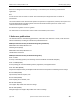
ASME A112.18.1-2018/CSA B125.1-18 Plumbing supply fittings Figure 8 Spray force test fixture set-up (See Clause 5.12.3.3.) Pivot rod 2.25 in T-slotted aluminum Weight holder Angle indicator Corner connector 12 in T-slotted aluminum Long screw 45° ± 1° Target Counter weight 16 in T-slotted aluminum Screw Tee connector 7.
ASME A112.18.1-2018/CSA B125.1-18 Plumbing supply fittings Figure 8 (Continued) 0.46 in 0.25 in 1/4 in — 20 threads b) Screw 1.5 in 0.25 in 1/4 in — 20 threads c) Long screw Notes: 1) The following are detailed drawings which may be used to construct a force balance tester. 2) The weight for the balance portion of the tester shall be 3.4 kg ± 0.5 (7.5 ± 1.0 lb). This weight was found to have a significant influence on the test results based on inter-laboratory comparison testing.
ASME A112.18.1-2018/CSA B125.1-18 Plumbing supply fittings Figure 8 (Continued) Long screw 3.0 in 4 in T-slotted aluminum 12 in T-slotted aluminum 13.0 in Weight holder See detail A 6.0 in Corner connector 13 in T-slotted aluminum Screw Angle Counter indicator weight Corner connector Ø18.0 13.0 in 4 in T-slotted aluminum Target 9.
ASME A112.18.1-2018/CSA B125.1-18 Plumbing supply fittings Figure 8 (Continued) 2.25 in T-slotted aluminum Pivot rod 4.25 in 2.25 in Tee connector 17.0 in 7.5 in T-slotted aluminum 16 in T-slotted aluminum Screw 3.0 in 13 .0 in 9.
ASME A112.18.1-2018/CSA B125.1-18 Plumbing supply fittings Figure 8 (Continued) Ø 18.0 in 0.25 ± 0.1 Ø 0.25 in f) Target Notes: 1) Cut from McMaster-Carr part number 8742K435. 2) Disk shall be flat and level within 6.35 mm (0.25 in). 3) Surface shall be free of cuts and grooves that could collect water.
ASME A112.18.1-2018/CSA B125.1-18 Plumbing supply fittings Figure 8 (Continued) 6.00 in 5.50 in 4.75 in 3.80 in 2.90 in 2.30 in 1.80 in 1.35 in 0.90 in 0.50 in 1.25 in 0.625 in 2× Ø 0.25 in Ø 0.55 in Ø 0.85 in Ø 0.44 in Ø 0.36 in Typ 118.0° 7× Ø 0.125 in 3× Ø 0.31 in 0.25 in 0.40 in 0.10 in 1.00 in 0.
ASME A112.18.1-2018/CSA B125.1-18 Plumbing supply fittings Figure 8 (Continued) 1.00 in 1.00 in 1.00 in 3.00 in 1.00 in 0.50 in 1.00 in 0.50 in 0.185 in 5 × Ø 0.26 in 3.
ASME A112.18.1-2018/CSA B125.1-18 Plumbing supply fittings Figure 8 (Continued) Ø 0.26 in 0.90 in 0.50 in 2.00 in 1.00 in R 13 typ 0.182 in 2.
ASME A112.18.1-2018/CSA B125.1-18 Plumbing supply fittings Figure 8 (Concluded) 1.0 in L 1.0 in Bar length L Dimension 12 inch bar 12.0 in 13 inch bar 13.0 in 14 inch bar 14.0 in 7.5 inch bar 7.5 in 4 inch bar 4.0 in L 1.0 in Ø 0.130 thru 1.0 in 0.75 in Bar length L Dimension 16 inch bar 16.0 in 2.25 inch bar 2.25 in k) Bar 9.5 in July 2018 © 2018 Canadian Standards Association Ø 0.
ASME A112.18.1-2018/CSA B125.1-18 Plumbing supply fittings Figure 9 Spray force test fixture set-up (See Clause 5.12.3.3.) 0 N (0 oz) Angle meter Force gauge Temporary work stand 90° Temporary clamp Target Position work stand force gauge to read 0 N (0 o) at 0.0° angle pointer a) 0.5 N (1.8 oz) Angle meter Force gauge Add sufficient counterweight to read 0.56 N (2.0 oz) on force gauge while holding 0.0° reading on angle pointer.
ASME A112.18.1-2018/CSA B125.1-18 Plumbing supply fittings Figure 10 Spray coverage test fixture (See Clause 5.12.4.2.) Figure 11 Spray coverage test fixture set-up ring (See Clause 5.12.4.2.
ASME A112.18.1-2018/CSA B125.1-18 Plumbing supply fittings Figure 12 Spray coverage test fixture set-up (See Clauses 5.12.4.2 and 5.12.4.5.) 450 ± 6 mm (18 ± 0.
ASME A112.18.1-2018/CSA B125.1-18 Plumbing supply fittings Annex A (informative) Unit conversion and rounding criteria Note: This Annex is an informative (non-mandatory) part of this Standard. A.1 Conversion The following conversion rules are used in this Standard: a) Zeros to the left of the first non-zero digit are not significant. b) If the number is greater than 1, all zeros to the right of the decimal point are significant.
ASME A112.18.1-2018/CSA B125.1-18 Plumbing supply fittings Annex B (normative) Tests by fitting type Note: This Annex is a mandatory part of this Standard.
July 2018 © 2018 Canadian Standards Association 86 X X 5.4 Flow rate X X X X X X X X X X X X X X X X X X X X X X X X X X X X X X X X X X X X X X X X X X X Fitting type 5.10 5.3.6.2 Diverter leakage — kitchen/ lavatory X X (See Clause 5.1.4.) Table B.1 Tests by fitting type Drainage test 5.3.6.1 5.3.4.3 Burst pressure — hose assembly Diverter leakage — bath/ shower 5.3.2 Burst pressure 5.2 X 5.3.5 Ball joint leakage Coatings X 5.
Automatic compensating valve © 2018 Canadian Standards Association X X 5.3.1.2 5.6.3.5.2 Pressure and temperature — valve closed Pullout strength X 5.3.1.3 5.1.1 and 5.1.2 Pressure and temperature — outlet blocked Preconditioning and installation X X X X X X X X X X X X X X X X X X X X X 5.5 Operating requirements X X X 5.6.3.5.3 X X Mandrel strength X X X Bidet 5.6.3.5.
X X X 5.7.2 5.8 4.