User Guide EVGA nForce 750i SLI Motherboard
Table of Contents Before You Begin… ..................................................................................................... vi Parts NOT in the Kit .................................................................................................vi Intentions of the Kit ..................................................................................................vi EVGA nForce 750i Motherboard..................................................................................
IEEE 1394a .................................................................................................... 16 USB Headers ................................................................................................. 16 Audio .................................................................................................................. 17 COM 1 ................................................................................................................ 17 Fan Connections ......................
Advanced Chipset Features................................................................................... 26 Spread Spectrum ............................................................................................... 26 System BIOS Cacheable ................................................................................... 26 Integrated Peripherals Menu.................................................................................. 27 IDE Function Setup ............................................
PnP/PCI Configuration Menu ................................................................................. 32 Init Display First.................................................................................................. 32 Reset Configuration Data................................................................................... 32 Resources Controlled By ................................................................................... 33 IRQ Resources.............................................
nForce 750i SLI Motherboard Before You Begin… Parts NOT in the Kit This kit contains all the hardware necessary to install and connect your new EVGA nForce® 750i SLI motherboard. However, it does not contain the following items that must be purchased separately to make the motherboard functional.
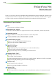
EVGA EVGA nForce 750i Motherboard Thank you for buying the EVGA NFORCE 750i SLI Motherboard. This motherboard offers the tools and performance PC users’ demand. When combined with two SLI-Ready NVIDIA GeForce graphics cards, you get innovative NVIDIA SLI Technology for enhanced system performance.
nForce 750i SLI Motherboard Onboard Audio Azalia High-Definition audio Supports 8-channel audio Supports S/PDIF output Supports Jack-Sensing function Green Function Supports ACPI (Advanced Configuration and Power Interface) Supports S0 (normal), S1 (power on suspend), S3 (suspend to RAM), S4 (Suspend to disk depends on OS), and S5 (soft - off) Expansion Slots Three PCI slots One PCI Express x1 slot Two PCI Express x16 Graphics slot compliant with PCI Express 2.
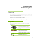
Unpacking and Parts Descriptions Unpacking The NVIDIA nForce 750i SLI motherboard comes with all the necessary cables for adding a motherboard to a new chassis. If you are replacing a motherboard, you may not need many of these cables. Be sure to inspect each piece of equipment shipped in the packing box. If anything is missing or damaged, contact your reseller. All parts shipped in this kit are RoHS-compliant (lead-free) parts.
2-Port SATA Power Cable (Qty Three) 1394 Cable Provides two additional 1394 ports to either the front or back panels of the chassis. USB 2.0 4-Port Cable Provides four additional USB ports to either the front or back panels of the chassis.
nForce 750i SLI Motherboard 1. CPU 775 Socket 11. Serial connector 21. Azalia HD Audio Header 2. CPU fan connector 12. Battery 22. FP Audio connector 3. DDR2 DIMM slots 0 - 3 13. Front panel connector 23. SPDIF connector 4. 24-pin ATX power connector 14. USB header 24. PCI slots 5. IDE connector 15. Reset CMOS button 25. PCI Express x16 slots 6. Chassis fan2 connector 16. Auxiliary fan connector 26.1394a connector 7. FDD connector 17. System fan connector 27. PCI Express x1 slot 8.
EVGA Hardware Installation This section will guide you through the installation of the motherboard. The topics covered in this section are: Preparing the motherboard Installing the CPU Installing the CPU fan Installing the memory Installing the motherboard Connecting cables and setting switches Safety Instructions To reduce the risk of fire, electric shock, and injury, always follows basic safety precautions.
nForce 750i SLI Motherboard Installing the CPU Be very careful when handling the CPU. Make sure not to bend or break any pins on the back. Hold the processor only by the edges and do not touch the bottom of the processor. Use the following procedure to install the CPU onto the motherboard. 1. Unhook the socket lever by pushing down and away from the socket. 2. Lift the load plate. There is a protective socket cover on the load plate to protect the socket when there is no CPU installed. 3.
EVGA Installing Memory DIMMs Your new motherboard has four 1.8V 240-pin slots for DDR2 memory. These slots support 256 MB, 512 MB, 1 GB, and 2 GB DDR2 memory modules. They also support dual channel DDR2 memory technology up to 10.7GB/s. There must be at least one memory bank populated to ensure normal operation. Use the following recommendations for installing memory. (See Figure 1 on page 4 for the location of the memory slots.) One DIMM: Install into slot 0.
nForce 750i SLI Motherboard Installing the Motherboard The sequence of installing the motherboard into the chassis depends on the chassis you are using and if you are replacing an existing motherboard or working with an empty chassis. Determine if it would be easier to make all the connections prior to this step or to secure the motherboard and then make all the connections. It is normally easier to secure the motherboard first.
EVGA Connecting Cables and Setting Switches This section takes you through all the connections and switch settings necessary on the motherboard. This will include: Power Connections 24-pin ATX power 8-pin ATX 12V power Internal Headers Front panel IEEE 1394a USB headers Audio Speaker COM FDD IDE Serial ATA II Chassis Fans Rear panel USB 2.0 Adapter Expansion slots See Figure 1 on page 4 to locate the connectors referenced in the following procedure.
nForce 750i SLI Motherboard Power Connections 24-pin ATX Power PWR1 is the main power supply connector located along the edge of the board next to the DIMM slots. Make sure that the power supply cable and pins are properly aligned with the connector on the motherboard. Firmly plug the power supply cable into the connector and make sure it is secure. v Pin Assignments Connector Pin Signal Pin Signal 1 +3.3V 13 +3.3V 2 +3.
EVGA Connecting IDE Hard Disk Drives The IDE connector supports Ultra ATA 133/100/66 IDE hard disk drives. 1. Connect the blue connector (the cable end with a single connector) to the motherboard. 2. Connect the black connector (the cable with the two closely spaced black and gray connectors) to the Ultra ATA master device. 3. Connect the gray connector to a slave device. If you install two hard disk drives, you must configure the second drive as a slave device by setting its jumper accordingly.
nForce 750i SLI Motherboard Connecting Serial ATA Cables The Serial ATA II connector is used to connect the Serial ATA II device to the motherboard. These connectors support the thin Serial ATA II cables for primary storage devices. The current Serial ATA II interface allows up to 300MB/s data transfer rate. There are four serial ATA connectors on the motherboard that support RAID 0,RAID 1, RAID 5, RAID 0+1 and JBOD configurations.
EVGA Connecting Internal Headers Front Panel Header The front panel header on this motherboard is one connector used to connect the following four cables. (see Table 2 for pin definitions): PWRLED Attach the front panel power LED cable to these two pins of the connector. The Power LED indicates the system’s status. When the system is in S0 status, the LED is on. When the system is in S4, S5 status, the LED is off. When the system is in S1, S3 status, the LED is blink.
nForce 750i SLI Motherboard IEEE 1394a The IEEE 1394 expansion cable bracket is provided in the box but if you do not require the additional external connections, you do not need to install it. 1. Secure the bracket to either the front or rear panel of your chassis (not all chassis are equipped with the front panel option). 2. Connect the two ends of the cables to the IEEE 1394 connectors on the motherboard.
EVGA Audio The audio connector supports HD audio standard and provides two kinds of audio output choices: the Front Audio, the Rear Audio. The front Audio supports re-tasking function. v Pin Assignments Connector Pin Signal Pin Signal 1 PORT1_L 2 AUD_GND 3 PORT1_R 4 PRECENCE_J 5 PORT2_R 6 SENSE1_RETURN 7 SENSE_SEND 8 Empty 9 PORT2_L 10 SENSE2_RETURN COM1 The motherboard kit provides an additional serial COM header for your machine.
nForce 750i SLI Motherboard Fan Connections There are six fan connections on the motherboard. The fan speed can be detected and viewed in the PC Health Status section of the CMOS Setup. The fans are automatically turned off after the system enters S3, S4 and S5 mode. CPU FAN CPU FAN: Connect the CPU fan to this connrctor. The CPU fan cable can be either a 3-pin or a 4-pin connector. Connect a 3-pin connector to pins 1, 2, and 3 on the motherboard connector.
EVGA Expansion Slots The EVGA nForce 750i SLI motherboard contains six expansion slots, three PCI Express slots and three PCI slots. For a full list of PCI Express x16 graphics card supported by this motherboard, go to www.nvidia.com/estore. PCI Slots The three PCI slots support many expansion cards such as a LAN card, USB card, SCSI card and other cards that comply with PCI specifications. When installing a card into the PCI slot, be sure that it is fully seated.
nForce 750i SLI Motherboard Onboard Buttons These onboard buttons include RESET, POWER and CMOS , lets you turn on/off the system easily, and convenient for clear CMOS RESET and POWER Button: These onboard buttons lets you turn on/off the system easily, it is especially handy for debugging or testing the system. CMOS Button: The motherboard uses the CMOS RAM to store all the set parameters. The CMOS can be cleared by press the CMOS button.
nForce 750i SLI Motherboard Configuring the BIOS This section discusses how to change the system settings through the BIOS Setup menus. Detailed descriptions of the BIOS parameters are also provided.
EVGA Main Menu The main menu allows you to select from the list of setup functions and two exit choices. Use the Page Up and Page Down keys to scroll through the options or press Enter to display the associated submenu. Use the arrow keys to position the selector in the option you choose. To go back to the previous menu, press Esc.
nForce 750i SLI Motherboard The following items on the CMOS Setup Utility main menu are commands rather than submenus: Load Fail Safe Defaults Load default system settings. Load Optimized Defaults Load default system settings. Set Supervisor Password/Set User Password Use this command to set, change, and disable the password used to access the BIOS menu. Save & Exit Setup Use this command to save settings to CMOS and exit setup.
EVGA Advanced BIOS Features Access the Advanced BIOS Features menu from the CMOS Utility Setup screen. Use the Page Up and Page Down keys to scroll through the options or press Enter to display the sub-menu. Use the arrow keys to position the selector in the option you choose. To go back to the previous menu, press Esc.
nForce 750i SLI Motherboard the + or – keys to move the device priority up or down in the list. To go back to the previous menu, press Esc. The Options are: Floppy Disk, LS120, ZIP100, USB-FDD0, USB-FDD1, USB-ZIP0, USB-ZIP1. Hard Disk Boot Priority Use this option to select the priority for HDD startup. Press Enter to see the list of bootable devices in your system. Use the arrow keys to go to the various devices. Then use the + or – keys to move the device priority up or down in the list.
EVGA MPS Version Control For OS Use this function to select the Multi-Processor Specification (MPS) version that BIOS passes to the operating system. Use the Page Up and Page Down keys to scroll through the options. Full Screen LOGO Show This option allows you to enable or disable the display of the full-screen logo when the system boots.
nForce 750i SLI Motherboard Integrated Peripherals Menu Select Integrated Peripherals from the CMOS Setup Utility menu and press Enter to display the Integrated Peripherals menu.
EVGA IDE DMA transfer access Use this function to enable or disable IDE DMA transfer access. Serial-ATA Controller This function allows you to enable specific SATA controllers, enable all controllers, or disable all controllers. The options available are [SATA-0], [SATA-0+1], [Enable All], and [Disabled]. IDE Prefetch Mode Use this function to enable or disable the IDE Prefetch mode. RAID Config Press Enter to display the RAID Config menu.
nForce 750i SLI Motherboard HD Audio This function on the Integrated Peripherals menu allows you to enable or disable the integrated high definition audio. MAC LAN Use these functions to set the MAC LAN to Auto or disable their functions. IEEE1394 controller This function on the Integrated Peripherals menu allows you to enable or disable the IEEE1394 (Firewire) interface. IDE HDD Block Mode Using this function on the Integrated Peripherals menu allows your IDE hard drive needs to support block mode.
EVGA Power Management Setup Select Power Management Setup from the CMOS Setup Utility menu and press Enter to display the Power Management Setup menu.
nForce 750i SLI Motherboard WOL(PME#) From Soft-Off This function on the Power Management Setup menu allows you to enable or disable WOL(PMW#) from soft-off. WOR(RI#) From Soft-Off This function on the Power Management Setup menu allows you to enable or disable WOR(RI#) from soft-off. Power On by Alarm This function on the Power Management Setup menu allows you to enable or disable the Poweron by alarm function. Set to [Disable] to prevent poweron by alarm.
EVGA Mouse Left Mouse Right Any Key PWRON After PWR-Fail This item enables your computer to automatically restart or return to its last operating status after power returns from a power failure. Off: The system stays off after a power failure. On: The system stays on after a power failure. PnP/PCI Configuration Menu Select PnP/PCI Configuration from the CMOS Setup Utility menu and press Enter to display the PnP/PCI Configuration menu.
nForce 750i SLI Motherboard Resources Controlled By This function on the PnP/PCI Configuration menu allows you to define if the BIOS can automatically configure all the boot and plug-and-play compatible devices or if you can manually select IRQ, DMA, and memory base address fields. Select [Auto(ESCD)] if you want the BIOS to automatically populate these fields. If you select [Manual] so you can assign the resources, IRQ Resources is enabled for input.
EVGA PC Health Status Select PC Health Status from the CMOS Setup Utility menu and press Enter to display the PC Health Status menu. Phoenix – AwardBIOS CMOS Setup Utility PC Health Status Dynamic Fan Control CPU [Press Enter] 47ºC/ 117ºF CPU VID CPU FSB Memory +3.3V +3.3V Dual +12V +5V +Vbat 1.28V 1.19V 1.90V 3.26V 3.26V 12.08V 4.93V 3.
nForce 750i SLI Motherboard Frequency/Voltage Control Select Frequency/Voltage Control from the CMOS Setup Utility menu and press Enter to display the Frequency/Voltage Control menu.
EVGA FSB & Memroy Config From this menu, you are able to specify frequency settings and memroy settings. Phoenix – AwardBIOS CMOS Setup Utility FSB & Memory Config Parameters Settings Current Value Current CPU Freq, MHz 2400.0 2400.0 CPU Multiplier [12X] 12X Main Level FSB - Memroy Clock Mode [Auto] 800.0 “CPUOC MAX” realizes the complete optimized memory settings when SLI-Ready memory is installed x FSB - Memory Ratio Auto x FSB (QDR), MHz Auto Actual FSB (QDR), MHz 800.
nForce 750i SLI Motherboard FSB (QDR), MHz Use the + or – keys to scroll through new values for the CPU FSB frequency or type in a new value. Note that the Actual FSB (QDR) reflects the actual frequency that takes effect on a reboot. MEM (DDR), MHz Use the + or – keys to scroll through new values for the memory frequency or type in a new value. Note that the Actual MEM (DDR) reflects the actual frequency that takes effect when the system reboots.
EVGA w Command Per Clock: This is the command timing setting on a per clock unit basis (options are 1T and 2T). w tRRD: RAS#-to-RAS# delay of different banks (options are 1 through 15). w tRC: RAS#-to-RAS# or auto refresh time of the same bank (options are 1 through 31). w tWR: The Write recovery time (options are 2 through 7). w tWTR: This is the minimum write-to-read delay with the same chip selected (options are 1 through 10). w tREF: This is the DRAM refresh rate (options are Auto, 7.8uS, and 3.
nForce 750i SLI Motherboard nForce SPP This function defines the core voltage level for the NVIDIA nForce SPP chip. Use the Page Up and Page Down keys to select a voltage (1.20V, 1.30V, 1.40V, 1.50V) or select [Auto] to automatically set the voltage. NF200 Voltage Level This function defines the core voltage level for the NVIDIA nForce NF200 chip. Use the Page Up and Page Down keys to select a voltage or select [Auto] to automatically set the voltage.
Installing Drivers and Software Note: It is important to remember that before installing the driver CD that is shipped in the kit, you need to load your operating system. The motherboard supports Windows XP 32bit and 64bit and is Vista-capable. The kit comes with a CD that contains drivers and additional NVIDIA software.
Driver Installation 3. 4. Insert the EVGA nForce 780i SLI installation CD for the motherboard included in the kit. The CD will autorun, install the drivers and utilities listed on the install screen. If the CD does not run, go to My Computer and click on the CD to open.
Appendix A. POST Codes for Tritium Platform This section provides the Award POST Codes (Table 6) and the NVMM POST Codes (Table 7) for Tritium platforms during system boot up. Table 1.
Using NVIDIA Software Award POST Codes Code Name Description 12 Test CMOS Test and Reset CMOS 13 Reserved 14 Load Chipset 15 Reserved Load Chipset Defaults 16 Init Clock 17 Reserved 18 Init CPU 19 Reserved 1A Reserved 1B Setup Interrupt Vector Table Initialize first 120 interrupt vectors with SPURIOUS_INT_HDLR and initialize INT 00h-1Fh according to INT_TBL 1C CMOS Battery Check Test CMOS and check Battery Fail 1D Early PM Early PM initialization 1E Reserved 1F Re-initial
Award POST Codes Code Name 2E Reserved 2F Reserved 30 Reserved 31 Reserved 32 Reserved 33 Early keyboard reset 34 Reserved 35 Test DMA Controller 0 36 Reserved 37 Test DMA Controller 1 38 Reserved 39 Test DMA Page Registers 3A Reserved 3B Reserved 3C Test Timer 3D Reserved 3E Test 8259-1 Mask 3F Reserved 40 Test 8259-2 Mask 41 Reserved 42 Reserved 43 Test Stuck Interrupt 44 Reserved 45 Reinit serial port 46 Reserved 47 EISA Test Description Early Keyboa
Using NVIDIA Software Award POST Codes Code Name 48 Reserved 49 Size Memory 4A Reserved 4B Reserved 4C Reserved 4D Reserved 4E Init APIC 4F Reserved 50 USB init 51 Reserved 52 Memory Test 53 Reserved 54 Reserved 55 CPU display 56 Reserved 57 PnP Init Display 58 Reserved 59 Setup Virus 5A Reserved 5B Awdflash Load 5C Reserved 5D Onboard I/O 5E Reserved 5F Reserved 60 Setup enable 61 Reserved 62 Reserved 63 Initialize Mouse Description Size base memor
Award POST Codes Code Name 64 Reserved 65 PS2 Mouse special 66 Reserved 67 ACPI init 68 Reserved 69 Init Cache 6A Reserved 6B Setup 6C Reserved 6D Initialize Floppy 6E Reserved 6F FDD install 70 Reserved 71 Reserved 72 Reserved 73 Initialize Hard Drive 74 Reserved 75 Detect HDD 76 Reserved 77 Detect serial ports 78 Reserved 79 Reserved 7A Detect parallel ports 7B Reserved 7C HDD Write Protect 7D Reserved 7E Reserved 7F POST error check 80 Reserved
Using NVIDIA Software Award POST Codes Code Name Description 82 Security Check Ask password security. 83 Write CMOS Write all CMOS values back to RAM and clear screen.
Award POST Codes Code Name Description B0 Spurious If interrupt occurs in protected mode. B1 Unclaimed NMI If unmasked NMI occurs, display Press F1 to disable NMI, F2 reboot. BF Program MCP To program chipset from defaults values E1-EF Setup Pages E1- Page 1, E2 - Page 2, etc.