Before You Begin… Parts NOT in the Kit This kit contains all the hardware necessary to install and connect your new EVGA nForce motherboard. However, it does not contain the following items that must be purchased separately to make the motherboard functional. Intel microprocessor: Intel Core 2 Extreme, Intel Core 2 Quad, Intel Core 2 Duo, Pentium EE, Pentium, and Celeron Socket 775 CPU’s.
• Supports hot plug • Up to ten USB 2.0 ports • Supports USB 2.
Hardware Installation This section will guide you through the installation of the motherboard. The topics covered in this section are: Preparing the motherboard • Installing the CPU • Installing the CPU fan • Installing the memory Installing the motherboard Connecting cables and setting switches Safety Instructions To reduce the risk of fire, electric shock, and injury, always follows basic safety precautions.
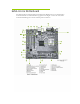
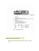
EVGA nForce Motherboard The EVGA nForce motherboard with the 600 series MCP processor is a PCI Express motherboard with an onboard GeForce graphics card. Figure 1 shows the 7150/630i motherboard and Figures 2 shows the back panel connectors.
Preparing the Motherboard The motherboard shipped in the box does not contain a CPU or memory. You need to purchase a CPU, a CPU heat sink/fan assembly, and memory module(s) to complete this installation.
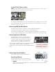
Installing the CPU Be very careful when handling the CPU. Hold the processor only by the edges and do not touch the bottom of the processor. Use the following procedure to install the CPU onto the motherboard. 1. Unhook the socket lever by pushing down and away from the socket. 2. Lift the load plate. There is a protective socket cover on the load plate to protect the socket when there is no CPU installed. 3. Remove the protective socket cover from the load plate. 4.
Determine if it would be easier to make all the connections prior to this step or to secure the motherboard and then make all the connections. Use the following procedure to install the I/O shield and secure the motherboard into the chassis. Note: Be sure that the CPU fan assembly has enough clearance for the chassis covers to lock into place and for the expansion cards. Also make sure the CPU Fan assembly is aligned with the vents on the covers.
8-pin ATX 12V Power (PWR2) PWR2, the 8-pin ATX 12V power connection, is used to provide power to the CPU. Align the pins to the connector and press firmly until seated. It is strongly recommended that you use an 8-pin ATX 12V power supply; however a four-pin power supply may be used. The 8 pin power connection is keyed for either a 4 pin or 8 pin connector to only go in one way. Connecting IDE Hard Disk Drives The IDE connector supports Ultra ATA 133/100/66 IDE hard disk drives.
PWRSW Attach the power button cable from the case to these two pins. Pressing the powerbutton on the front panel turns the system on off rather than using the power supply button. HD_LED RESET Attach the hard disk drive indicator LED cable to these two pins. The HDD indicator LED indicates the activity status of the hard disks. Attach the Reset switch cable from the front panel of the case to these two pins. The system restarts when the RESET switch is pressed.
FDD Connector The motherboard supports a standard 360K, 720K, 1.2M, 1.44m, and a 2.88M floppy disk drive (FDD). Speaker The speaker connector is used to connect the chassis speakers to the motherboard. Please refer to item 9 in figure 1 Motherboard. Expansion Slots The EVGA nForce motherboard contains four expansion slots, two PCI Express slots and two PCI slots. For a full list of PCI Express x16 graphics card supported by this motherboard, go to www.evga.com/products/.
On-board LED Codes On-board LED Codes Code(hex) Name 01 Reserved Description 02 Jumps to E000 segment Execution of POST routines in E000 03 Early Superio Init Early Initialized the super IO 04 Reserved 05 Blank video 06 Reserved 07 Init KBC Keyboard controller init 08 KB test Test the Keyboard 09 Reserved 0A Mouse 0B Reserved 0C Reserved 0D Reserved 0E CheckSum 0F Reserved 10 Autodetect 11 Reserved 12 Test CMOS 13 Reserved 14 Load Chipset 15 Reserved 16 Ini
Code(hex) Name 1E Reserved 1F Re-initial KB 20 Reserved 21 HPM init Description Load keyboard matrix Init Heuristic Power Management (HPM) 22 Reserved 23 Program chipset Early Programming of chipset registers 24 Init PNP Init PNP 25 Shadow VBIOS Shadow system/video BIOS 26 Clock Gen Init onboard clock generator and sensor 27 Setup BDA Setup BIOS DATA AREA (BDA) 28 Reserved 29 CPU Speed detect 2A Reserved 2B Init video 2C Reserved 2D Video memory test 2E Reserved 2F
Code(hex) Name Description 45 Reinit serial port Reinitialize Preboot agent serial port 46 Reserved 47 EISA Test 48 Reserved 49 Size Memory 4A Reserved 4B Reserved 4C Reserved 4D Reserved 4E Init APIC 4F Reserved 50 USB init Initialize 51 Reserved 52 Memory Test 53 Reserved 54 Reserved 55 CPU display 56 Reserved 57 PnP Init 58 Reserved 59 Setup Virus 5A Reserved 5B Awdflash Load 5C Reserved 5D Onboard I/O Init 5E Reserved 5F Reserved 60 Setup enable
Code(hex) Name Description 6D Initialize Floppy Initialize floppy disk drive 6E Reserved 6F FDD install 70 Reserved 71 Reserved 72 Reserved 73 Initialize Hard Drive 74 Reserved 75 Detect HDD 76 Reserved 77 Detect serial ports 78 Reserved Install FDD and setup BIOS data area parameters Initialize hard drive controller IDE device detection Initialize serial ports 79 Reserved 7A Detect parallel ports 7B Reserved 7C HDD Write Protect 7D Reserved 7E Reserved 7F POST err
Code(hex) Name Description C1 Memory Presence Base memory detect C2 Early Memory Board Initialization C3 Extend Memory Turn on extended memory, cache initialization C4 Special Display First display initialization C5 Early Shadow Early shadow enable for fast boot C6 Cache presence External caches FF Boot