Table of Contents Congratulations! ................................................................................................2 Parts NOT in the Kit ...........................................................................................2 Hardware Installation ............................................................................................ 2 Preparing the Motherboard ................................................................................3 Installing the CPU .....................
Congratulations! Thank you for purchasing this EVGA P55 Chipset based motherboard. This motherboard from EVGA offers high performance, quality features and superior support. If you have any questions about this product please visit www.evga.com to read the EVGA FAQ, visit our forums or contact us directly. Parts NOT in the Kit This kit contains all the hardware necessary to install and connect your new EVGA P55 Motherboard.
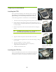
Preparing the Motherboard Installing the CPU Be very careful when handling the CPU. Hold the processor only by the edges and do not touch the contacts on the motherboard or CPU. Any physical damage to the motherbard pins will void the warranty. Use the following procedure to install the CPU onto the motherboard: 1. Unhook the socket lever by pushing down and away from the socket. 2. Pull the socket lever back and the load plate will automatically lift.
Installing System Memory (DIMMs) Your new motherboard has four 240-pin slots for DDR3 memory. These slots support 512 MB, 1GB, 2GB, and 4GB DDR3 technologies. There must be at least one memory bank populated to ensure normal operation. Use the following the recommendations for installing memory. One DIMM: If using 1 DIMM (Single Channel), install into: DIMM slot 1. Two DIMMs: If using 2 DIMMs (Dual Channel), install into: DIMM slots 1 and 3.
Securing the Motherboard into a System Case Most system cases have a base with mounting studs or spacers to allow the motherboard to be secured to the chassis and help to prevent short circuits. If there are studs that do not align with a mounting hole on the motherboard, it is recommended that you remove that stud to prevent the possibility of a short circuit. 1. Carefully place the motherboard onto the stand offs located inside the chassis. 2. Align the mounting holes with the stand offs. 3.
24-pin ATX Power (ATXPOWER) ATXPOWER is the main power supply connector located along the edge of the board next to the DIMM slots. Make sure that the power supply cable and pins are properly aligned with the connector on the motherboard. Firmly plug the power supply cable into the connector and make sure it is secure. Power Connector Plug power cable from system power supply to ATXPOWER Connector 1 13 Pin 12 24 Signal Pin Signal 1 +3.3V 13 +3.3V 2 +3.
Front Panel Header (F_PANEL) The front panel header on this motherboard is one connector used to connect the following four cables. PLED Attach the front panel power LED cable to these two pins of the connector. The Power LED indicates the system’s status. When the system is turned on, the LED is on. When the system is turned off, the LED is off. PWRBTN Attach the power button cable from the case to these two pins.
Enter BIOS Setup The BIOS is the communication bridge between hardware and software. Correctly setting the BIOS parameters is critical to maintain optimal system performance and stability. Use the following procedure to verify/change BIOS settings. 1. Power on the computer. 2. Press the Del key when the following message briefly displays at the bottom of the screen during the Power On Self Test (POST). Press F9 to Load Defaults, DEL to enter Setup.
Installing Drivers and Software The CD that has been shipped with the EVGA P55 Motherboard contains the following software and drivers: Chipset Drivers Audio drivers LAN Drivers RAID Drivers Adobe Acrobat Reader User’s Manual Windows XP/Vista/7 Driver Installation 1. Insert the Intel P55 installation CD for the motherboard included in the kit. 2. The CD will autorun, install the drivers and utilities listed on the install screen.
もくじ ようこそ! ........................................................................................................ 11 同梱されない付属品 ......................................................................................... 11 ハードウェアを取り付ける ................................................................................ 12 始める前に ...................................................................................................... 12 CPU を取り付ける .......................................................................
ようこそ! EVGA P55 チップセット搭載マザーボードをお買い上げいただきありがとうございます。 このマザーボードは EVGA から高性能、高品質の機能、および優れたサポートを提供するマザーボー ドです。 この製品に関する質問がありましたら、www.evga.com にアクセスして、EVGA FAQ を読むか、 フォーラムを訪問するか、または直接連絡してください。 同梱されない付属品 このバッケージには EVGA P55 マザーボードに取り付け、または接続するのに必要なハードウェアが付 いています。ところが 、以下の商品はマザーボードを機能的にする必要項目ですが、同梱されませんの で、別途にご購入ください。 Intel プロセッサ 1156 ソケット DDR3 システム メモリ Socket 1156 ソケット冷却ファン PCI Express グラフィックカード 電源ユニット EVGA は、お客様が適切なシステムの機能性のため、必要な付属品を購入したと仮定しますので、本マ ザーボードでは CPU をサポートするものに関するは、下記へご訪問ください。 http://www.
ハードウェアを取り付ける この章では、マザーボードの設置手順についてご案内します。また、それに関連する項目、以下 の通りです: マザーボードを取り付ける CPU を取り付ける CPU ファンを取り付ける メモリを取り付ける マザーボードを取り付ける 配線ケーブル 始める前に CPU を取り付ける CPU の取り扱いにはよくご注意ください。必ずプロセッサのエッジ 部分を持ち、、マザーボードや CPU の接点には触れないでくだ さい。マザーボードピンへのいかなる物理的なダメージにより、保 証が無効となります。以下の手順で、CPU をマザーボードに取り 付けます: 1. ソケットレバーを押し下げ、ソケットから離すようにして、レバーを外に 動かします。 2.
3. CPU ソケットからソケットカバーを垂直の方向に取り出します。 注意: ピンの損傷を防ぐため、CPU を取り外したときに、保護カバーは必ず収納しなければなりま りません。 4. ソケットの突出をプロセッサの切り欠きに合わせます。 5. プロセッサを傾けたり滑らせたりせずに、ソケットにまっすぐ下ろします。 6. ロードプレートを押し下げて閉じ、CPU の上に置きます。 7. ロードプレートの先端はスクリューキャップの上にあるのを確保するた め、もう一度ソケットレバーを引き返します。 ソケットの突出をプ 8.
Two DIMMs: 2 DIMMs (デュアルチャンネル) を使用する場合, DIMM スロット 1 と 3 に取り付けます. Four DIMMS: 4 DIMMs (デュアルチャンネル) を使用する場合, DIMM スロット 2, 1, 4, と 3 に取り付 けます. DIMM スロット 2 (XMM2) DIMM スロット 1 (XMM1) DIMM スロット 4 (XMM4) DIMM スロット 3 (XMM3) メモリ DIMMsの取り付けについては、以下の手順をご参照くだい。DIMM スロットの中央付 近に 1 つだけのギャップがあることにご注意ください 。コンポーネントを正常に取り付けるために、 このスロットは、メモリ DIMM 上のギャップに必ず合わせます。モジュールクリップの外部を押し、 DIMM スロットのロックを解除します。 1. モジュールクリップの外部を押し、DIMM スロットのロックを解除します。 2.
I/O シールドを取り付ける マザーボードには、無線周波数の送波を防ぐために使用されたり、ほこりや異物の侵入から内部のコン ポーネントを保護したり、シャーシ内の空気の流れを助けたりする I/O シールドが付いています。 マザーボードを取り付ける前に、先にシャーシの内側に I/O シールドを取り付けます。I / O シールドを 押して、しっかりと正しい位置に収まるように、ご確認ください。 マザーボードをケースへ固定する ほとんどのケースには、マザーボードをシャーシに固定し、また短絡を防ぐために、取り付け用ネジと、ス ペーサーが付いています。 ネジはマザーボード上のネジ穴に合わせない場合、短絡の可能性を防ぐため、スペーサーを取り外す のをお勧めします。 1. 2. 慎重に、マザーボードをシャーシ内のマザーボードマウンタの上に置きます。 3. I / O シールドに、コネクタを合わせます。 4. アセンブリに関する指示により、ファンはシャーシ通気孔に合わせていることを確認します。 5.
24-ピン ATX 電源 (ATXPOWER) ATXPOWER は DIMM スロットの隣に、ボードの縁のに沿って置かれる主電源用のコネクタです。電源 供給ケーブルとピンは適切にマザーボード上のコネクタに合わせて付けられていることを確認します。電 源供給ケーブルをコネクタにしっかりと埋め込み、それは安全であることを確認してください。 電源コネクタ 電源ユニットから電源ケーブ ルを ATXPOWER に差し込み ます。 コネクタ 1 ピン 12 13 24 信号 ピン 信号 1 +3.3V 13 +3.3V 2 +3.3V 14 -12V 3 GND 15 GND 4 +5V 16 PS_ON 5 GND 17 GND 6 +5V 18 GND 7 GND 19 GND 8 PWROK 20 RSVD 9 +5V_AUX 21 +5V 10 +12V 22 +5V 11 +12V 23 +5V 12 +3.
シリアル ATA ケーブルの接続 シリアル ATA II コネクタは、マザーボードにシリアル ATA II デバイスを接続するために使用されます。 これらのコネクタは、主要なストーレジデバイス用の薄型シリアル ATA II ケーブルをサポートします。現 在のシリアル ATA II インターフェイスは最大 300MB/sの転送速度が可能です。 このマザーボードに内部シリアル ATA コネクタが 6(5)つあります。これらのコネクタはすべての拡張カ ードと干渉しないようにアングルに設計されます。 フロントパネルヘッダー (F_PANEL) このマザーボード上のフロントパネルヘッダーは、次の 4 本のケーブルを接続するために使用されるコ ネクタです。 PLED フロントパネルの電源 LED ケーブルを 2 つのコネクタピンに取り 付けます。電源 LED は、システムのステータスを示します。 システムがオンになると、LED が点灯します。 システムがオフになると、LED が消灯します。 PWRBTN 電源ボタンのケーブルをこの 2 つのピンに取り付けます。また、フロントパ ネルの電源ボタンを押し、システ
RESET ケースのフロントパネルから Reset スイッチケーブルをこの 2 本のピンに取り付けます。 RESET スイッチを押すと、システムが再起動します。 拡張スロット PCI Express x1 スロット PCI Express x1 スロットは EVGA Killer Xeno のネットワーク用カードやサウンドカードなどの PCIe x1 カ ードに対応するように設計されます。この x1 スロットは 250 MB /秒の帯域幅をサポートします。 PCI Express x16/x8/x1 スロット これらの PCI Express スロットはグラフィックカードと PCI Express x1 装置のために留保されます。本マザ ーボードの設計は、複数のグラフィックカード技術をサポートします。 PCI Express グラフィックカードを取り付けるときは、必ずクリップスナップがカードを所定の場所にロック するのを確認します。 空白カバーを固定するため,カードの金属製のブラケットをネジで、シャーシ背面パネルには固定します。 18
BIOS のセットアップ BIOS はハードウェアとソフトウェアとの間に通信するブリッジです。BIOS パラメータの正確 な設定によって、重要なシステムのパフォーマンスと安定性を維持できます。 以下の手順で BIOS 設定を確認/変更します。 1. コンピュータの電源をオンにします。 2. 自己診断テスト(POST)チェック中に、次のメッセージが画面の最下段に簡潔に表示されるとき、 Del キーを押します。 Press F9 to Load Defaults, DEL to enter Setup.
ドライバとソフトウェアのインストール EVGA P55 マザーボードと同梱される CD には、次のソフトウェアとドライバが付いています: チップセットドライバ オーディオ ドライバ LAN ドライバ RAID ドライバ Adobe Acrobat Reader プログラム ユーザー マニュアル Windows XP/Vista/7 ドライバのインストール 1. 同梱にはマザーボード用 Intel P55 のインストール CD を差し込みます。 2.
Tabla de Contenidos ¡Felicidades! ........................................................................................................... 22 Partes no incluidas en Juego ................................................................................. 22 Instalación de Hardware .............................................................................................22 Preparación de Placa base ...................................................................................
¡Felicidades! Gracias por comprar este Chipset EVGA P55 basadO EN placa base. La placa base de EVGA se ofrece un alto rendimiento, características de calidad y apoyo superior. Si usted tiene alguna pregunta sobre este producto, por favor visite www.evga.com para leer FAQ de EVGA, visite nuestros foros o entre en contacto con nosotros directamente. Partes no incluidas en Juego Este producto se contiene todos los hardwares necesarios para instalar y conectar su nueva Placa base EVGA P55.
Preparación de Placa base Instalación de CPU Tenga mucho cuidado al tomar CPU. Tome el procesador sólo por los bordes y no toque la placa base o CPU. Cualquier daño físico a los pines de la placa base se anulará la garantía. Utilice el procedimiento siguiente para instalar CPU en la placa base: 1. Desenganche la palanca del zócalo por presionando hacia abajo y lejos del zócalo. 2. Tire de la palanca del zócalo y la placa de carga se va a elevar automáticamente.
Instalación de Memoria de sistema (DIMMs) Su nueva placa base hay cuatro ranuras de 240-pin para la memoria DDR3. Estas ranuras se apoya las tecnologías DDR3 de 512 MB, 1GB, 2GB y 4GB. Debe contar se con un banco último de memoria por lo menos para garantizar el funcionamiento normal. Utilice las recomendaciones siguientes para la instalación de memoria. Un DIMM: Se utiliza 1 DIMM (Ú nico Canal), instale a: DIMM ranura 1. Dos DIMMs: Se utiliza 2 DIMMs (Dual Canal), instale a: DIMM ranuras 1 y 3.
Instalación de Capa protectora de I/O La placa base se viene con una capa protectora de I/Oque es utilizada para bloquear las transmisiones de radiofrecuencia, y proteger los componentes internos del polvo y los objetos extraños, y garantizar el flujo del aire correcto dentro del chasis. Antes de instalar la placa base, instale la capa protectora de I/O de la parte interior del chasis. Presione la capa protectora de I/O en su lugar y asegúrese de que esté instalada seguramente.
24-pin ATX Potencia (ATXPOWER) ATXPOWER es el conector de la fuente de alimentación principal situado al borde de la placa cerca de las ranuras DIMM. Asegúrese de que el cable de la fuente de alimentación y los pines están alineados con el conector de la placa base correctamente. Conecte el cable de la fuente de alimentación al conector y asegúrese de fijar bien.
Conexión de Cables Seriales ATA El conector Serial ATA II se utiliza para conectar el dispositivo Serial ATA II a la placa base. Estos conectores se apoyan los cables finos de Serial ATA II para los dispositivos del almacenamiento primario. La actual interfaz Serial ATA II se permite hasta la velocidad de transferencia de datos de 300MB/s. Hay seis (5) conectores internos Serial ATA en esta placa base. Estas conexiones se diseñan para ser un ángulo para no interferir con cualquier tarjeta de expansión.
Cabecera de Panel Frontal (F_PANEL) La cabecera del panel frontal en esta placa base es un conector utilizado para conectar los cuatro cables siguientes. PLED Conecte el cable de LED de la fuente de alimentación del panel frontal a estos dos pines del conector. El LED de fuente de alimentación se indica el estado del sistema. Cuando el sistema está encendido, el LED se brilla. Cuando el sistema está apagado, el LED no se brilla.
Ranuras de Expansión PCI Express x1 Ranura PCI Express x1 ranura se diseña para acomodar las tarjetas PCIe x1, tales como una Tarjeta de Red EVGA Killer Xeno o Tarjeta de Sonido. La x1 ranura se proporciona un ancho de banda de 250 MB/seg. PCI Express x16/x8/x1 Ranuras Estas ranuras PCI Express se reservan por Tarjetas Gráficas y los dispositivos PCI Express x1. El diseño de esta placa base se apoya la tecnología de Tarjetas Gráficas múltiples.
Entrar en Configuración de BIOS El BIOS es el puente de comunicación entre el hardware y el software. La configuración correcta de los parámetros del BIOS es importante para mantener el rendimiento y la estabilidad óptimo del sistema. Utilice el procedimiento siguiente para comprobar/cambiar las configuraciones de BIOS. 1. Encienda el ordenador. 2.
Instalación de Controladores y Software El CD integrado por la placa base EVGA P55 se cuenta con el software y los controladores siguientes: Controladores de Chipset Controladores de Audio Controladores de LAN Controladores de RAID Adobe Acrobat Reader Manual del Usuario Instalación de Controladores de Windows XP/Vista/7 1. 2. Inserte el CD de instalación de Intel P55 para la placa base incluido en el juego.
Inhaltsverzeichnis Herzlichen Glückwunsch! ....................................................................................... 33 Teile die NICHT im Lieferumfang enthalten sind ................................................... 33 Hardware Installation ..................................................................................................33 Vorbereitung des Motherboards ............................................................................ 34 Installation der CPU ......................
Herzlichen Glückwunsch! Vielen Dank, dass Sie sich für dieses auf dem EVGA P55 Chipset basierende Motherboard entschieden haben. Dieses Motherboard von EVGA bietet High-Performance, qualitätvolle Ausstattung und überlegenen Support. Sollten sie Fragen zu diesem Produkt haben so besuchen sie bitte die Webseite www.evga.com und werfen Sie einen Blick in das EVGA FAQ, besuchen Sie das Forum oder treten Sie direkt mit uns in Kontakt.
Vorbereitung des Motherboards Installation der CPU Gehen Sie sehr sorgsam mit der CPU um. Fassen Sie die CPU nur an den Ecken und berühren Sie nicht die Anschlüsse am Motherboard oder an der CPU. Bei jeglichen Schäden an den Pins des Motherboards erlischt die Garantie. Gehen Sie wie folgt vor um die CPU auf dem Motherboard zu installieren: 1. Drücken Sie den Hebel am Anschluss ein wenig nach unten und weg vom Anschluss um ihn zu entriegeln. 2.
Installation des CPU Kühlers Viele verschiedene Arten von CPU Kühlern können mit diesem Motherboard verwendet werden. Folgen Sie den Anweisungen ihres CPU Kühlers. Stelle Sie sicher, dass die Blasrichtung ihres Kühlers zu der Bauart Ihres Gehäuses passt. Installation des Arbeitsspeichers (DIMMs) Ihr neues Motherboard besitzt vier 240-pin Steckplätze für DDR3 Arbeitsspeicher. Diese Steckplätze unterstützten den Anschluss von 512 MB, 1GB, 2GB, und 4GB DDR3 Speicherkarten.
Installation des Motherboards Die Installation des Motherboards in das Systemgehäuse hängt mit dessen Aufbau und der Tatsache zusammen, ob es sich um leeres Gehäuse handelt oder bereits ein Motherboard installiert ist. Entscheiden Sie, ob es einfacher ist die bisher beschriebenen Schritte vor oder nach dem Einbau des Motherboards zu machen. Normalerweise erfolgt zuerst die Installation des Motherboards in das Gehäuse. Gehen Sie wie folgt vor um das Motherboard und die I/O Blende anzubringen.
Verbindung der Kabel Dieser Abschnitt erklärt alle nötigen Verbindungen und Anschlüsse des Motherboards.
24-Pin ATX Stromkabel (ATXPOWER) ATXPOWER ist der hauptsächliche Stromanschluss und befindet sich an der Ecke der Platine neben den Steckplätzen des Arbeitsspeichers. Stellen Sie sicher, dass das Stromkabel richtig an den Anschluss angeschlossen ist. Drücken Sie ihn fest in den Anschluss und gehen Sie sicher, dass er richtig sitzt. Stromanschluss Schließen Sie das Kabel der Systemstromversorgung an den ATXPOWER an Anschluss 1 Pin 12 13 24 Signal Pin Signal 1 +3.3V 13 +3.3V 2 +3.
Verbindung der Seriellen ATA Anschlüsse Der Serielle ATA II Anschluss wird zur Verbindung des Seriellen ATA II Gerätes mit dem Motherboard benutzt. Diese Anschlüsse unterstützten den Anschluss der dünnen ATA II Kabel für primäre Speichergeräte. Die verwendete Serielle ATA II Schnittstelle erlaubt Transferraten von bis zu 300MB/s. Es gibt sechs interne (5) Serielle ATA Anschlüsse auf diesem Mainboard. Diese Anschlüsse sind so ausgerichtet, dass sie nicht den Anschluss anderer Steckkarten behindern.
Das Festplatten LED zeigt den Status und die Aktivität der Festplatte an.. RESET Anschluss des Reset Knopfes an diese 2 Stecker. Das System startet neu, wenn der RESET Knopf betätigt wird. Weitere Steckplätze PCI Express x1 Steckplätze Der PCI Express x1 Steckplatz ist für das Anbringen von PCIe x1 Karten vorgesehen, wie beispielsweise eine EVGA Killer Xeno Netzwerk Karte oder eine Soundkarte. Der x1 Steckplatz unterstützt Bandbreiten von bis zu 250 MB/sec.
Aufrufen des BIOS Setup Das BIOS ist die zentrale Kommunikationsschnittstelle zwischen Hardware und Software. Eine korrekte Eingabe der BIOS Parameter ist entscheidend in Bezug auf die Aufrechterhaltung einer optimalen Systemperformance und Stabilität. Gehen Sie wie folgt vor um Einstellungen des BIOS zu überprüfen/ändern. 1. Starten Sie den Computer. 2. Drücken Sie ENTF sobald folgende Nachricht an der Unterseite ihres Bildschirmes während des Power On Self Test (POST) erscheint.
Installation von Treibern und Software Die CD, die im Lieferumfang des EVGA P55 Motherboards enthalten ist, enthält folgende Treiber und Software: Chipset Treiber Audio Treiber LAN Treiber RAID Treiber Adobe Acrobat Reader Bedienungsanleitung Windows XP/Vista/7 Treiber Installation 1. Legen Sie die Intel P55 Installations-CD für das Motherboard (enthalten im Lieferumfang) in das CDLaufwerk ein. 2.
Table des matères Félicitations ! .......................................................................................................... 44 Parties exclues de ce kit ........................................................................................ 44 Installation de matériel ................................................................................................44 Préparation de la carte mère..................................................................................
Félicitations ! Merci d'acheter cette carte mère basée sur jeu de puces d'EVGA P55. Cette carte mère d'EVGA offre de hautes performances, des caractéristiques de qualité et supports supérieurs. Si vous avez des questions au sujet de ce produit, veillez visiter www.evga.com pour lire le FAQ d'EVGA, ou contactez-nous directement. Parties exclues de ce kit Ce kit contient tout le matériel nécessaire pour installer et connecter votre nouvelle carte mère d'EVGA P55.
Préparation de la carte mère Installation de l'unité centrale de traitement Installation de ventilateur de l'unité centrale de traitement Installation de mémoire Installation de la carte mère Cables de connection 45
Préparation de la carte mère Installation de l'unité centrale de traitement Soyez très prudent lorsque vous manipulez l'unité centrale de traitement. Tenez le processeur uniquement par les bords et ne touchez pas les contacts sur la carte mère ou le processeur. Tout dommage physique aux groupilles de la carte mère annulera la garantie. Utilisez la procédure suivante pour installer l'unité centrale de traitement sur la carte mère: 1. Décrochez le levier de douille en abaissant et à partir de la douille. 2.
Installtion de ventilateur de l’unité centrale de traitement Il existe de nombreux types différents de ventilateurs qui peuvent être utilisées avec cette carte mère. Suivez les instructions qui sont venus avec votre ventilateur ensemble. Assurez-vous que l'orientation du ventilateur est adapté à votre type de châssis et de votre ventilateur. Installation de mémoire du système (DIMMs) Votre nouvelle carte mère dispose de quatre connecteur à 240 broches pour la mémoire DDR3.
2. Alignez le module de mémoire DIMM au connecteur de DIMM, et insérez le module verticalement dans le connecteur de DIMM. Les clips en plastique sur les deux côtés du connecteur de DIMM verrouiller automatiquement le module DIMM dans le connecteur. Installation de la carte mere L’ordre d'installer la carte mère dans un boîtier système dépend du châssis que vous utilisez et si vous remplacez une carte mère existante ou travailler avec un boîtier système vide.
6. Veiller à ce que le ventilateur est aligné avec le châssis de ventilation en fonction des instructions d'assemblage du ventilateur. 7. Fixez la carte mère avec des vis. Cables de connexion This section takes you through all the necessary connections on the motherboard.
Connexion d’alimentation à 24 broches de ATX (ATXPOWER) ATXPOWER est le connecteur d’alimentation principal trouvé le long du bord de la planche à côté des connecteurs de mémoire. Assurez-vous que le câble d'alimentation et les broches sont bien alignés avec le connecteur sur la carte mère. Branchez fermement le câble d'alimentation dans le connecteur et assurez-vous qu'il soit bloqué.
Câbles de connexion de Série ATA Ce connecteur de Série ATA II est utilisé pour connecter les périphériques de Serié ATA II à la carte mère. Ces connecteurs supportent les câbles minces de Serie ATA II pour les périphériques de stockage primaire. L'interface courante de Serial ATA II permet un taux de transfert de données à hauteur de 300 Mos. Il y a six (5) connecteurs internes de Série ATA sur cette carte mère.
these two pins. The HDD indicator LED indicates the activity status of the hard disks. RESET Raccordez le câble de l'interrupteur de réinitialisation du panneau fontal du boîtier du système à ces deux broches. Le système redémarre lorsque l'interrupteur de réinitialisation est pressée. Connecteurs d’Expansion Connecteurs de PCI Express x1 Le connecteur de PCI Express x1 est conçu pour adapter aux cartes de PCIe x1 cards, telles qu’une carte de céseau de EVGA Killer Xeno ou une Carte de son.
Entrer Dans l’installation BIOS Le BIOS Le BIOS est le pont de communication entre le matériel et le logiciel. L'établissement correct des paramètres de BIOS est critique pour maintenir l'exécution et la stabilité de système optimales. Utilisez la procédure suivante pour vérifier / modifier les paramètres du BIOS. 1. Allumer l’ordinateur. 2. Appuyer sur la touché “Suppré lorsque le message suivant s’affiche brièvement au bas de l’écran pendant “l'autotest de fonctionnement” (POST).
Installation de pilote et logiciel Le CD qui a été livré avec la carte mère P55 EVGA contient le logiciel et pilotes suivants: Pilotes de jeux de puceChipset Drivers Pilotes Audio Pilotes de LAN Pilotes de RAID Adobe Acrobat Reader Manuel d’utilisation Installation de pilote de Windows XP/Vista/7 1. Insérez le CD d'installation de Intel P55 pour la carte mère inclus dans le kit. 2. Le CD marchera autamatiquement, et installera les pilotes et utilitaires énumérés sur l’écran d’installation.
目錄 歡迎您! .............................................................................................................................. 56 非本產品包裝附帶配件 .................................................................................................... 56 硬體安裝 ................................................................................................................................ 56 準備安裝主機板 ................................................................................................................
恭喜您! 感謝您購買本款採用 EVGA P55 晶片組之主機板。 本款 EVGA 主機板提供了高效能、高品質的功能以及優異的支援服務。如果您有任何關於本產品 的問題,請參閱 www.evga.com 網站的 EVGA FAQ 問與答頁面、論壇或是直接與我們連絡。 不在本產品配件包內之配件 本產品包含了所有需要安裝與連接至您全新的 EVGA P55 主機板之硬體配件。然而並不包含以下 主機板正常運作必備但必須自行購買之項目。 Intel 1156 針腳中央處理器 (CPU) DDR3 系統記憶體 1156 針腳處理器散熱風扇 PCI Express 顯示卡 電源供應器 EVGA 假設您已經購買好所有可讓主機板正常運作的必備配件。要了解本主機板所支援的處理器完 整清單,請參閱 http://www.evga.
準備安裝主機板 安裝中央處理器 (CPU) 拿取 CPU 時務必非常小心,只可夾住 CPU 的邊緣並勿觸摸 CPU 或是主機板的接腳部位。任何造成主機板接腳部位的實體 損傷都會使保固服務無效。 使用下列步驟安裝 CPU 至主機板: 1. 將插座的固定拉桿向下壓 並從插座側邊向外移開 。 2. 將固定拉桿向後推動,固定金屬板即會自動被扳起。這裡有一片保護 蓋是為了保護插座在沒有安裝 CPU 時,不會受到損傷。 3. 將 CPU 插座裡的保護蓋以垂直的方式拿起。 注意: 您 必須 保留此保護蓋,以便在您移除 CPU 而插座針腳無法受到保護時使用。 4. 將處理器的缺口處對準插座上的凸起處。 5. 以非傾斜或滑入的方式將處理器以垂直方向放入插座之中。 6. 將固定金屬板輕輕放回,讓其平置於處理器上方。 7. 將固定拉桿再次放回,並確保固定金屬板的前端缺口處已 正確滑入螺栓下方。 8.
安裝處理器風扇 本主機板可搭配許多不同種類的處理器風扇。請參照您的風扇散熱 裝置所提供的指示說明。並確認風扇安裝的方向皆是符合主機板固 定座種類與風扇的設計。 安裝系統記憶體 (DIMM) 您的主機板提供了四條 240 腳位的 DDR3 記憶體插槽。這些插槽可支援採用 DDR3 技術的 512 MB、1GB、2GB 與 4GB 記憶體。至少需要安裝一組記憶體模組至插槽中以確保主機板可正常運 作。使用以下建議方式進行記憶體的安裝。 一組記憶體模組:如果使用一支記憶體模組 (單通道),安裝至 DIMM 插槽 1。 二組記憶體模組:如果使用二支記憶體模組 (雙通道),安裝至 DIMM 插槽 1 與 3。 四組記憶體模組:如果使用四支記憶體模組 (雙通道),安裝至 DIMM 插槽 2、1、4 與 3. DIMM 插槽 2 (XMM2) DIMM 插槽 1 (XMM1) DIMM 插槽 4 (XMM4) DIMM 插槽 3 (XMM3) 依照以下步驟安裝記憶體模組。請注意到記憶體插槽上僅有一個靠近中央的凸起處,此凸起處必 須對準記憶體模組的缺口處以確保安裝正確。 1.
安裝主機板 安裝主機板至系統機殼的順序,將會依您使用的機殼差異,以及是替換已存在機殼內的主機板, 或是安裝至未使用過的機殼而有所不同。請先判斷何者為較容易的安裝方式:是事先連接所有裝 置再行安裝主機板至機殼內,或是先安裝主機板再連接所有裝置。一般而言,先安裝主機板至機 殼內是較容易進行的安裝方式。 依照以下步驟安裝 I/O 擋板與固定主機板至機殼之中。 安裝 I/O 擋板 本產品包裝內含有一片 I/O 擋板可供於阻隔射頻訊號、阻擋灰塵或異物進入機殼內部,以及提高 機殼內部的空氣對流。安裝主機板之前,先從機殼 內部 安裝 I/O 擋板。將 I/O 擋板壓入正確的位 置並確認它是否安裝妥當。 固定主機板至系統機殼 大多數的系統機殼皆配置了螺栓或間隔插座,可讓主機板固定至機殼並防止短路。如果有部分螺 栓未對應到主機板上的螺絲孔,建議將其移除以避免發生短路。 1. 小心地將主機板放置於機殼的螺柱上。 2. 將螺絲孔對準螺柱。 3. 將連接埠對準 I/O 擋板。 4. 確認散熱風扇已依照風扇安裝指南對齊機殼的通風孔。 5.
24 腳位 ATX 電源(ATXPOWER) 4 腳位 ATX 12 伏電源 (ATX_CPU) 內部接頭 前置面板 Serial ATA II 連接埠 擴充卡插槽 60
24 腳位 ATX 電源(ATXPOWER) ATXPOWER 是主要的電源插槽,位置靠近主機板邊緣的記憶體模組插槽旁。請確認電源供應線 的針腳已與主機板上的插槽對齊。將電源供應線平穩地插入電源插槽,並確保它已連接穩固。 電源插槽 將電源供應線從系統電源供應 器連接至 ATXPOWER 插槽 針腳 12 1 13 24 訊號 針腳 訊號 1 +3.3V 13 +3.3V 2 +3.3V 14 -12V 3 GND 15 GND 4 +5V 16 PS_ON 5 GND 17 GND 6 +5V 18 GND 7 GND 19 GND 8 PWROK 20 RSVD 9 +5V_AUX 21 +5V 10 +12V 22 +5V 11 +12V 23 +5V 12 +3.
連接 Serial ATA 連接線 Serial ATA II 連接埠可供連接 Serial ATA II 裝置至主機板。這些連接埠可支援薄型 Serial ATA II 連接線連接至主儲存裝置。目前的 Serial ATA II 介面最高可支援每秒 300MB 的傳輸速率。 本主機板上一共有 6 (5) 個內部 Serial ATA 插槽。這些插槽的角度已經過設計,不會影響任何擴 充卡的配置。而這些連結皆支援 RAID 0、RAID1、RAID5 與 RAID 10 功能。 62
前置面板排針 (F_PANEL) 本主機板的前置面板排針可用於連接以下四種連接線。 PLED 將前置面板的電源指示燈連接線連接至此 2 腳位。而電源指 示燈可顯示系統的狀態。 當電腦為開機的狀態時,指示燈會持續亮著,而在關機時, 指示燈則會熄滅。 PWRBTN 連接機殼上的電源開關按鍵連接線至此 2 腳位。按壓前置面 板的電源開關按鍵即可開機或關機,而不需要使用主機板上 的按鍵。 HDLED 連接硬碟動作指示燈連接線至此 2 腳位。硬 碟指示燈可顯示硬碟的存取動作。 RESET 連接前置面板上的重置鍵連接線至此 2 腳 位。按壓 RESET 鍵可以重新啟動電腦。 擴充卡插槽 PCI Express x1 擴充卡插槽 本 PCI Express x1 插槽是專為 PCIe x1 擴充卡設計,例如 EVGA Killer Xeno 網路卡或音效卡。本 x1 插槽可提供每秒 250MB 的頻寬。 63
PCI Express x16/x8/x1 擴充卡插槽 這些 PCI Express 插槽是專為顯示卡以及 PCI Express x1 裝置而保留。本主機板可以支援多顯示 卡技術。 安裝 PCI Express 顯示卡時,確保卡榫已扣上並固定住顯示卡,再使用鎖住閒置插槽的螺絲將顯 示卡的金屬擋板鎖於主機背板上。 64
進入 BIOS 設定 BIOS 是硬體與軟體溝通的橋梁。正確的 BIOS 設定對於維持最佳的運作效能及穩定性非常重要。 請使用以下步驟確認/更新 BIOS 設定。 1. 啟動電腦。 2. 當螢幕底部在系統自我測試(POST)過程顯示以下訊息時,按下 Del 鍵。 Press F9 to Load Defaults, DEL to enter Setup. 按下 Del 鍵將會帶您進入 AMI BIOS CMOS 設定程式 主選單可讓您選擇各種功能設定與兩種離開此程式的選項。使用+ / -鍵可調整各功能的值,或按 Enter 鍵進入各項設定的子選單。使用鍵則可移動指標至您希望選擇的選項。按 Esc 可回到上 一層選單。 BIOS SETUP UTILITY Main Main Advanced Power Security Boot Exit Use [ENTER], [TAB] System Overview Or [SHITF-TAB] to Select a field.
安裝驅動程式與軟體 隨 EVGA P55 主機板出貨的 CD 包含了以下軟體與驅動程式: 晶片組驅動程式 音效卡驅動程式 LAN 網路卡驅動程式 RAID 磁碟陣列驅動程式 Adobe Acrobat 閱讀程式 使用手冊 安裝 Windows XP/Vista/7 驅動程式 1. 插入配件中的 Intel P55 主機板安裝光碟。 2.
目录 歡迎您! .............................................................................................................................. 68 不在套件内之配件 ............................................................................................................ 68 硬件安装 ................................................................................................................................ 68 准备安装主板 .............................................................................................................
恭喜您! 感谢您购买本款采用 EVGA P55 芯片组之主板。 本款 EVGA 主板提供了高效能、高质量的功能以及优异的支持服务。如果您有任何关于本产品的 问题,请访问 www.evga.com 网站的 EVGA FAQ 问与答页面、论坛或是直接与我们连络。 不在套件内之配件 本产品包含了所有需要安装与连接至您全新的 EVGA P55 主板之硬件配件。然而并不包含以下主 板正常运作必备但必须自行购买之项目。 Intel 1156 针脚中央处理器 (CPU) DDR3 系统内存 1156 针脚处理器散热风扇 PCI Express 显卡 电源供应器 EVGA 假设您已经购买好所有可让主板正常运作的必备配件。要了解本主板所支持的处理器完整列 表,请访问 http://www.evga.
准备安装主板 安装中央处理器 (CPU) 拿取 CPU 时务必非常小心,只可夹住 CPU 的边缘并勿触摸 CPU 或是主板的接脚部位。任何造成主板接脚部位的实体损 伤都会使保证服务无效。 使用下列步骤安装 CPU 至主板: 1. 将插座的固定拉杆向下压 并从插座侧边向外移开 。 2. 将固定拉杆向后推动,固定金属板即会自动被扳起。这里有一片保 护盖是为了保护插座在没有安装 CPU 时,不会受到损伤。 3. 将 CPU 插座里的保护盖以垂直的方式拿起。 注意: 您 必须 保留此保护盖,以便在您拿开 CPU 而插座针脚无法受到保护时使用。 4. 将处理器的缺口处对准插座上的凸起处。 5. 以非倾斜或滑入的方式将处理器以垂直方向放入插座之中。 6. 将固定金属板轻轻放回,让其平置于处理器上方。 7. 将固定拉杆再次放回,并确保固定金属板的前端缺口处已正确滑入螺 栓下方。 8.
安装处理器风扇 本主板可搭配许多不同类型的处理器风扇。请参照您的风扇散热 设备所提供的指示说明。并确认风扇安装的方向皆符合主板固定 座种类与风扇的设计。 安装系统内存 (DIMM) 您的主板提供了四条 240 脚位的 DDR3 内存插槽。这些插槽可支持采用 DDR3 技术的 512 MB、 1GB、2GB 与 4GB 内存。至少需要安装一组内存至插槽中以确保主板可正常运作。使用以下建议 方式进行内存的安装。 一组内存:如果使用一支内存 (单通道),安装至 DIMM 插槽 1。 二组内存:如果使用二支内存 (双通道),安装至 DIMM 插槽 1 与 3。 四组内存:如果使用四支内存 (双通道),安装至 DIMM 插槽 2、1、4 与 3. DIMM 插槽 2 (XMM2) DIMM 插槽 1 (XMM1) DIMM 插槽 4 (XMM4) DIMM 插槽 3 (XMM3) 依照以下步骤安装内存。请注意到内存插槽上仅有一个靠近中央的凸起处,此凸起处必须对准内 存的缺口处以确保安装正确。 1. 将内存插槽的固定夾向外扳开。 2.
安装主板 安装主板至系统机箱的顺序,将会依您使用的机箱差异,以及是替换已存在机箱内的主板,或是 安装至未使用过的机箱而有所不同。请先判断何者为较容易的安装方式:是事先连接所有设备再 安装主板至机箱内,或是先安装主板再连接所有设备。一般而言,先安装主板至机箱内是较容易 进行的安装方式。 依照以下步骤安装 I/O 挡板与主板至机箱之中。 安装 I/O 挡板 本产品包装内含有一片 I/O 挡板可供于阻隔射频信号、阻挡灰尘或异物进入机箱内部,以及提高 机箱内部的空气对流。安装主板之前,先从机箱 内部 安装 I/O 挡板。将 I/O 挡板压入正确的位置 并确认它是否安装妥当。 固定主板至系统机箱 大多数的系统机箱皆配置了螺栓或间隔插座,可让主板固定至机箱并防止短路。如果有部分螺栓 未对应到主板上的螺丝孔,建议将其去除以避免发生短路。 1. 小心地将主板放置于机箱的螺柱上。 2. 将螺丝孔对准螺柱。 3. 将接口对准 I/O 挡板。 4. 确认散热风扇已依照风扇安装指南对齐机箱的通风孔。 5.
24 脚位 ATX 电源(ATXPOWER) 4 脚位 ATX 12 伏特电源 (ATX_CPU) 内部接头 前置面板 Serial ATA II 接口 扩展卡插槽 24 脚位 ATX 电源(ATXPOWER) ATXPOWER 是主要的电源插槽,位置靠近主板边缘的内存插槽旁。请确认电源供应电缆的针脚 已与主板上的插槽对齐。将电源供应电缆平稳地插入电源插槽,并确保它已连接稳固。 电源插槽 将电源供应电缆从系统电源供 应器连接至 ATXPOWER 插槽 1 13 针脚 12 24 信号 针脚 信号 1 +3.3V 13 +3.3V 2 +3.3V 14 -12V 3 GND 15 GND 4 +5V 16 PS_ON 5 GND 17 GND 6 +5V 18 GND 7 GND 19 GND 8 PWROK 20 RSVD 9 +5V_AUX 21 +5V 10 +12V 22 +5V 11 +12V 23 +5V 12 +3.
4 脚位 ATX 12 伏特电源 (ATX_CPU) ATX_CPU 4 脚位或 8 脚位的 ATX 12 伏特电源电缆是用于供给电力予 CPU 使用。 将针脚与插槽对齐并稳固地压下直到其连接稳固。若使用 8 脚位的插头,将会有 4 根针 脚悬挂于插槽外。 连接 Serial ATA 传输电缆 Serial ATA II 接口可供连接 Serial ATA II 设备至主板。这些接口可支持薄型 Serial ATA II 传输电 缆连接至主储存设备。目前的 Serial ATA II 接口最高可支持每秒 300MB 的传输速率。 本主板上一共有 6 (5) 个内部 Serial ATA 插槽。这些插槽的角度已经过设计,不会影响任何扩展 卡的配置。而这些连结皆支持 RAID 0、RAID1、 RAID 5 与 RAID 10 功能。 73
前置面板排针 (F_PANEL) 本主板的前置面板排针可用于连接以下四种连接电缆。 PLED 将前置面板的电源指示灯连接电缆连接至此 2 脚位。而 电源指示灯可显示系统的状态。 当计算机处于开启状态时,指示灯会持续亮着,而在关 闭时,指示灯则会熄灭。 PWRBTN 连接机箱上的电源开关按键连接电缆至此 2 脚位。按压 前置面板的电源开关按键即可开机或关机,而不需要使 用主板上的按键。 HDLED 连接硬盘动作指示灯连接电缆至此 2 脚位。 硬盘指示灯可显示硬盘的存取动作。 RESET 连接前置面板上的重置键连接电缆至此 2 脚 位。按压 RESET 键可以重新启动计算机。 扩展卡插槽 PCI Express x1 扩展卡插槽 本 PCI Express x1 插槽是专为 PCIe x1 扩展卡设计,例如 EVGA Killer Xeno 网卡或声卡。本 x1 插槽可提供每秒 250MB 的带宽。 74
PCI Express x16/x8/x1 扩展卡插槽 这些 PCI Express 插槽是专为显示适配器以及 PCI Express x1 设备而保留。本主板可以支持多显 示适配器技术。 安装 PCI Express 显卡时,确保固定夹已扣上并固定住显卡,再使用锁住闲置插槽的螺丝将显卡 的金属挡板锁于主机后面板上。 75
进入 BIOS 设置 BIOS 是硬件与软件沟通的桥梁。正确的 BIOS 设置对于维持最佳的运作效能及稳定性非常重要。 请使用以下步骤确认/更新 BIOS 设置。 1. 启动计算机。 2. 当屏幕底部在系统自我测试(POST)过程显示以下信息时,按下 Del 键。 Press F9 to Load Defaults, DEL to enter Setup. 按下 Del 键将会带您进入 AMI BIOS CMOS 设置程序 主菜单可让您选择各种功能设置与两种离开此程序的选项。使用+ / -键可调整各功能的值,或按 Enter 键进入各项设置的子菜单。使用键则可移动箭头至您希望选择的选项。按 Esc 可回到上 一层菜单。 BIOS SETUP UTILITY Main Main Advanced Power Security Boot Exit Use [ENTER], [TAB] System Overview Or [SHITF-TAB] to Select a field.
安装驱动程序与软件 随 EVGA P55 主板出货的 CD 包含了以下软件与驱动程序: 芯片组驱动程序 声卡驱动程序 LAN 网卡驱动程序 RAID 磁盘阵列驱动程序 Adobe Acrobat 阅读程序 用户手册 安装 Windows XP/Vista/7 驱动程序 1. 插入配件中的 Intel P55 主板安装光盘。 2.