PCoIP® Multi-Monitor Deployment Guide TER0905009 Issue 2
PCoIP Multi-Monitor Deployment Guide Teradici Corporation #101-4621 Canada Way, Burnaby, BC V5G 4X8 Canada p +1 604 451 5800 f +1 604 451 5818 www.teradici.com The information contained in this document represents the current view of Teradici Corporation as of the date of publication.
PCoIP Multi-Monitor Deployment Guide Revision History Version Date Description 1 Jul 09, 2009 Initial Release 2 Aug 24, 2009 Clarified the reason of disabling WOL on the slave Host Card in Section 2.
PCoIP Multi-Monitor Deployment Guide Contents REVISION HISTORY ...................................................................................................... 2 CONTENTS .................................................................................................................... 3 TABLE OF FIGURES ..................................................................................................... 4 DEFINITIONS ..................................................................................
PCoIP Multi-Monitor Deployment Guide Table of Figures Figure 1-1 Quad Monitors Setup Using Two PCoIP Kits .................................................... 7 Figure 1-2: Portal Initial Setup ............................................................................................ 9 Figure 1-3: Host Card Initial Setup.................................................................................... 10 Figure 2-1 Disable WOL Header......................................................................
PCoIP Multi-Monitor Deployment Guide Definitions AC Alternating Current ATX Advanced Technology Extended BIOS Basic Input/Output System DHCP Dynamic Host Configuration Protocol DNS Domain Name System DVI Digital Visual Interface IP Internet Protocol MAC Media Access Control NIC Network Interface Card OS Operating System OSD On Screen Display PC Personal Computer PCIe Peripheral Component Interconnect Express ® PC-over-IP ® Personal Computer over Internet Protocol PCoIP see PC-o
PCoIP Multi-Monitor Deployment Guide Introduction This document provides step-by-step instructions on deploying a basic multi-monitor PCoIP deployment including setting up a quad monitor system using two PCoIP Host Cards in a host PC along with two Portals. The document also describes how users can install more than two pairs of Host and Portal devices for a single PC to support more than four monitors. It also describes other considerations that should be taken into account for this deployment.
PCoIP Multi-Monitor Deployment Guide 1 Quad Monitor PCoIP Deployment This section describes a basic quad monitor deployment. A PCoIP kit consists of a Host Card and Desktop Portal pair and supports up to two monitors. To support up to four monitors on the client side, a multi-monitor PCoIP deployment can be implemented using two PCoIP kits. Here the Hosts Cards and Portals are configured to use static IP addresses.
PCoIP Multi-Monitor Deployment Guide 1.2 Host Cards Installation This section outlines the installation using Host Card A as the master and Host Card B as the slave. Host Card A, the master, can be used for remote power management. If you wish to enable power management, refer to Section 2.1 below for more information. Host Installation Process 1. Power down your host PC and unplug the AC power cord. 2. Install two graphics cards with two DVI ports each that support a total of up to four monitors.
PCoIP Multi-Monitor Deployment Guide conflicts. If the deployment is to be used on its own network, then any four unique IP addresses on the same subnet may be used. This example uses the following example static IP addresses and MAC addresses: • Host Card A: 192.168.1.200 (MAC: AA-AA-AA-AA-AA-AA) • Host Card B: 192.168.1.201 (MAC: BB-BB-BB-BB-BB-BB) • Portal A: 192.168.1.202 • Portal B: 192.168.1.
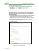
PCoIP Multi-Monitor Deployment Guide b. Step 2: Uncheck Enable DHCP and enter the IP address you want to use for Portal A, for example, 192.168.1.202. Enter Subnet Mask (e.g. 255.255.255.0) and Gateway (e.g. 192.168.1.1). c. Step 3: Select PCoIP for Session Type and Identify Host by IP address. Enter Host A’s static IP address and MAC address, e.g. 192.168.1.200 and AA-AA-AA-AA-AA-AA. d. Select Apply to accept the changes made. You can restart the Portal 5.
PCoIP Multi-Monitor Deployment Guide d. Step 4: Select Apply to accept the changes made. Do not restart the Host PC. 9. Configure Host Card B by repeating Steps 6-8 except using Host Card B’s DHCP address to configure it to the new static IP address, e.g. 192.168.1.201. 10.Shutdown and restart the PC using the PC power. Establish PCoIP Session 1. On Portal A, press the Enter key on the keyboard to establish a PCoIP session to Host Card A. 2.
PCoIP Multi-Monitor Deployment Guide 2 Advanced Configuration This section outlines configuration for more advanced features of remote power management and Standalone mode. 2.1 Remote Power Management The PCoIP Host Card and Portal optionally enable remote power management, i.e. you can power on/off and wake the PC using the Portal. Enabling power management requires connecting a cable from the Host Card to the PC.
PCoIP Multi-Monitor Deployment Guide 2. Connect the white end of the Host Card Power Button Cable to the Power Button Cable Connector on the Host Card. The Power Button Cable Connector on the Host card is labeled “JP5 PWR BTN”. 3. Disconnect the PC’s front-panel On/Off switch cable from the motherboard’s header, and locate the Power On/Off signal pins. Connect the red wire on the Host Card Power Button Cable to the positive terminal of the Power On/Off pin, and the black wire to the negative terminal.
PCoIP Multi-Monitor Deployment Guide You can install the Host Card somewhere inside or outside of the host PC. The Host Card draws power from a floppy drive connector (+5V/+12V) of your ATX power supply in your host PC. The slave PCoIP Host Card and Portal are used for video transmission only (USB and audio are not supported when a Host Card is in Standalone mode). Note: If there is not a free PCIe slot available for Host Card B, although not ideal, Host Card B can be installed in Standalone mode.
PCoIP Multi-Monitor Deployment Guide Figure 2-4 Floppy Drive Power Connector TER0905009 Issue 2 15
PCoIP Multi-Monitor Deployment Guide 3 Other Considerations This section outlines other options for a multi-monitor deployment. 3.1 Auto-Reconnect The Auto-Reconnect feature automatically reconnects PCoIP sessions when they are disconnected by either network or power issues without user interaction. Enabling Auto-Reconnect 1. On the management PC, browse to Portal A using the static IP address configured in Section 1.4. 2. Log in and select the Configuration->Session menu item.
PCoIP Multi-Monitor Deployment Guide 3.3 PCoIP Management Console The PCoIP Management Console (PCoIPMC) can be used to manage PCoIP devices in larger multi-monitor PCoIP deployments. The PCoIPMC allows easy PCoIP pairings as well as parameter configuration (e.g. USB permissions, bandwidth settings, etc.) for various users groups. The PCoIPMC can be used with or without a Connection Broker. For details about using the PCoIP Management Console, refer to PCoIP Management Console User Manual (TER0812002). 3.