
Use and Care Manual


12
www.evolutionpowertools.com
(5.5) ASSEMBLY & PREPARATION
PERMANENTLY MOUNTING A
CHOP SAW
WARNING: Only attempt the following
procedures with the machine disconnected
from the mains power supply.
The base on this chop saw has four mounting
holes (in the corners) through which suitable
bolts (not supplied) can be placed to secure the
machine.
Site the machine giving consideration to the
following guidelines:
• To avoid injury from flying debris, position
the saw so that other people or bystanders
cannot stand too close (or behind) it.
• Locate the saw on a firm, level surface where
there is plenty of room for handling and
properly supporting the workpiece.
• Ensure that the workbench or other
supporting structure is firm and stable and
does not ‘rock’.
• Ensure that the power cord cannot become
entangled with any part of the machine
during cutting operations.
• Ensure that the power cord is routed in such
a way that it does not pose a trip (or any
other type) of hazard to the operator or
any bystanders.
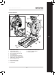
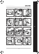
TRANSPORTING THE SAW
Only transport these machines with the Cutting
Head in the locked down position (Fig. 1) and
the Locking Pin fully engaged in its socket.
UNLOCKING THE CUTTING HEAD
NOTE: We recommend that the operator keep
hold of the cutting handle throughout this
process to ensure a controlled transition of the
cutting head to the upper position.
• Gently press down on the Cutting Handle.
Pull out the Locking Pin. (Fig. 2) Allow the
Cutting Head to rise to its upper position
(Fig. 3).
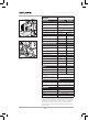
REMOVING OR INSTALLING A BLADE
WARNING: Only use genuine Evolution blades
designed for this machine - see page 10
It is recommended that the operator considers
wearing protective gloves when handling the
blade during installation or when changing the
machines blade.
REMOVING A BLADE:
• Ensure that the Cutting Head is in its upper
position.
• Using the Hex Key supplied, loosen the front
arbor cover bolt and rotate the arbor cover out
of the way. (Fig. 4).
• Press the arbor lock button (labelled) (Fig. 5)
and use the supplied hex key to remove the
blade bolt. The blade may rotate slightly until
the arbor lock engages.
• Remove the arbor bolt, washer and outer
blade flange. (Fig. 6).
• Open the blade guard and carefully remove
the old blade. Leave the inner blade flange
in place.
INSTALLING A BLADE:
• Install the new blade, ensuring the directional
arrow on the blade matches the direction of
the arrow on the upper blade guard.
• Allow the blade guard to close and refit the
outer blade flange and washer.
• Partially refit the arbor bolt, press the arbor
lock button and fully tighten with the supplied
hex key.
After replacing a blade, always run the machine,
without load to ensure the blade is seated correctly.
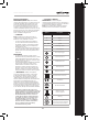
CUTTING ANGLE ADJUSTMENT
TO ANGLE THE REAR VICE JAW:
• Loosen the fence securing bolt (Fig. 7)
• Rotate the fence to the desired angle and
retighten the bolt.
TO REMOVE THE REAR VICE JAW:
Completely remove fence securing bolts and
washers. (Fig. 8)
• Completely remove both fence securing bolts,
washer and spacer (Fig. 9) that secure the rear
vice jaw to the machines base.
• Place the vice jaw into its new service position.
• Refit the fence securing bolts, washers and
spacer.
CHIP COLLECTION
A specially shaped steel shield (Fig. 10)
prevents the cut debris from being expelled