EN MITRE SAW STAND (005-0001) Original Instructions DE FR Original written in UK English Date Published: 21 / 11 / 2016
ENGLISH EN Original Instructions DE FR
www.evolutionpowertools.
www.evolutionpowertools.com IMPORTANT Please read these operating and safety instructions carefully and completely. For your own safety, if you are uncertain about any aspect of using this equipment please access the relevant Technical Helpline, the number of which can be found on the Evolution Power Tools website. We operate several Helplines throughout our worldwide organization, but Technical help is also available from your supplier. WEB www.evolutionpowertools.com EMAIL enquiries@evolutionpowertools.
www.evolutionpowertools.com GENERAL SAFETY INSTRUCTIONS STAND SPECIFIC SAFETY INSTRUCTIONS Read these instructions before using this mitre saw stand. Do not modify or use this stand for any purpose other than that for which it was designed. • For maximum stability use the mitre stand only on a flat, level surface. • Be careful when raising or lowering the stand to prevent trapped fingers or hands. • Ensure that the snap buttons on each leg are in the locked position.
www.evolutionpowertools.
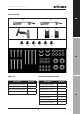
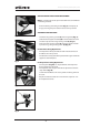
www.evolutionpowertools.com DEPLOYING THE LEGS PRIOR TO ASSEMBLY Note: It is much easier to set up or knock down the stand without a saw being attached. • Push the locking/unlocking button (Fig. 1) and deploy all 4 legs, ensuring they are locked in their service position. ASSEMBLY INSTRUCTIONS Fig. 1 • Screw the long locking screws (F) into the guides. (Fig. 2) • Slide the work support brackets (D) onto the extension arms and lock in place with a long locking screw (F). (Fig.
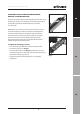
www.evolutionpowertools.com CHECKING and ADJUSTING THE SAW MOUNTING BRACKET CLAMPING PRESSURE EN The pressure exerted by the clamping mechanism within a saw mounting bracket can be adjusted. The clamping pressure of each bracket should be checked before it is attached to a mitre saw. When fitted across the mitre saw stands two main crossbars, and with the locking handle in the down (locked) position, a bracket should be firm and exhibit no signs movement.
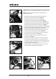
www.evolutionpowertools.com MOUNTING EVOLUTION MITRE SAW TO THE MITRE STAND Note: The Evolution Mitre Saw Stand is suitable for most Evolution Mitre Saws. Fig. 7 Fig. 8 • Remove and safely store the four (4) plastic feet from underneath the base of the mitre saw. (Fig. 7) • Remove and safely store the stability block from underneath the positive stop locking lever. (Fig. 8) • Attach the machine to the saw mounting brackets (A) using suitable bolts, washers and locknuts etc.
www.evolutionpowertools.com MOUNTING UNUSUAL or UNCOMMON MITRE SAWS If your mitre saw is ‘uncommon’ or ‘unusual’ an adaptor plate may be necessary. EN The adaptor plate can be bolted to the two (2) saw mounting brackets, and when attached to the stand should provide a suitable mounting platform for most mitre saws. The mitre saw can then be screwed or bolted to the adaptor plate. We recommend at least 25 mm thick plywood or a piece of 32mm or 40mm kitchen worktop for this adaptor plate.
EN DEUTSCH DE Übersetzung ursprünglichen Anweisungen FR
www.evolutionpowertools.
www.evolutionpowertools.com WICHTIG Bitte lesen Sie diese Betriebsanleitung und die Sicherheitshinweise sorgfältig und vollständig. Zu Ihrer eigenen Sicherheit, wenn Sie unsicher über irgendeinen Aspekt der Verwendung dieser Ausrüstung sind, bitte auf das entsprechende Technische Helpline, kann die Anzahl der dem auf die Evolution Power Tools Website gefunden werden. Wir betreiben mehrere Helplines in unserer weltweiten Organisation, sondern Technische Hilfe ist auch von Ihren Lieferanten. WEB www.
www.evolutionpowertools.com ALLGEMEINE SICHERHEITSHINWEISE SPEZIFISCHE SICHERHEITSHINWEISE FÜR DEN STÄNDER Lesen Sie diese Hinweise bevor Sie den Gehrungssägeständer verwenden. Modifizieren Sie diesen Ständer nicht und verwenden Sie ihn nicht für andere Zwecke als die, für die er entwickelt wurde. • Sorgen Sie für einen hindernisfreien und gut belüfteten Arbeitsbereich. Ein nicht aufgeräumter Arbeitsbereich kann Unfälle hervorrufen. • Berücksichtigen Sie Umgebungseinflüsse auf den Arbeitsbereich.
www.evolutionpowertools.
www.evolutionpowertools.com AUSKLAPPEN DER FÜSSE VOR DER MONTAGE Hinweis: Es ist viel einfacher, den Ständer aufzustellen oder zusammenzuklappen, wenn keine Säge daran befestigt ist. • Drücken Sie den Verriegelungs-/Entriegelungsknopf (Abb. 1) und klappen Sie alle 4 Füße aus; stellen Sie dabei sicher, dass Sie in Ihrer Arbeitsposition verriegelt sind. MONTAGEANWEISUNGEN Abb. 1 • Schrauben Sie die langen Befestigungsschrauben (F) in die Führungen. (Abb.
www.evolutionpowertools.com PRÜFEN UND EINSTELLEN DES KLEMMDRUCKS DER SÄGEBEFESTIGUNG EN Der in einer Sägebefestigung durch den Klemmmechanismus ausgeübte Druck kann eingestellt werden. Der Klemmdruck jeder Befestigung sollte geprüft werden bevor sie an einer Gehrungssäge angebracht wird. Eine Befestigung sollte fest sein und sich nicht bewegen wenn sie über den Querträgern des Gehrungssägeständers angebracht ist und sich der Arretiergriff in der unteren (arretierten) Position befindet.
www.evolutionpowertools.com BEFESTGUNG EINER EVOLUTION GEHRUNGSSÄGE AM GEHRUNGSSÄGESTÄNDER Hinweis: Der Evolution Gehrungssägeständer ist für die meisten Evolution Gehrungssägen geeignet. Abb. 7 Abb. 8 Abb. 9 Abb. 10 • Entfernen Sie die vier (4) Kunststofffüße von der Unterseite der Gehrungssäge und bewahren Sie sie sicher auf. (Abb. 7) • Entfernen Sie den Stabilisierblock von der Unterseite des Anschlagarretiergriffs und bewahren Sie ihn sicher auf. (Abb.
www.evolutionpowertools.com BEFESTIGEN UNGEWÖHNLICHER ODER UNÜBLICHER GEHRUNGSSÄGEN EN Wenn Ihre Gehrungssäge ‚ungewöhnlich‘ oder ‚unüblich‘ ist, kann es sein, dass eine Adapterplatte erforderlich ist. Die Adapterplatte kann an die zwei (2) Sägebefestigungen geschraubt werden und eine Befestigungsplattform für die meisten Gehrungssägen bieten wenn sie am Ständer angebracht ist. Die Gehrungssäge kann dann an die Adapterplatte geschraubt werden.
EN DE FRANÇAIS Traduction des instructions d’origine FR
www.evolutionpowertools.
www.evolutionpowertools.com IMPORTANT S’il vous plaît lire les instructions de fonctionnement et de sécurité attentivement et complètement. Pour votre propre sécurité, si vous êtes incertain à propos de n’importe quel aspect de l’utilisation de cet équipement s’il vous plaît accéder à la ligne d’assistance technique concerné, dont le nombre peut être trouvé sur le site Evolution Power Tools.
www.evolutionpowertools.com CONSIGNES GENERALES DE SECURITE CONSIGNES DE SECURITE SPECIFIQUES AU SUPPORT Lisez ces instructions avant d’utiliser ce support de scie à onglet. N’apportez aucune modification à ce support et ne l’utilisez pas à des fins autres que celles pour lesquelles cet outil a été conçu. • Gardez un espace de travail propre, dégagé et bien ventilé. Le désordre renforce les risques d’accident. • Pensez aux conditions de travail.
www.evolutionpowertools.
www.evolutionpowertools.com DEPLOIEMENT DES PIEDS AVANT ASSEMBLAGE Note: II est beaucoup plus facile de monter ou de démonter le support sans que la scie y soit installée. • Poussez le bouton de verrouillage et de déverrouillage (Fig. 1) et déployez les 4 pieds en vous assurant qu’ils sont bloqués en position de travail. INSTRUCTIONS D’ASSEMBLAGE Fig. 1 • Vissez les écrous de fixation longs (F) dans les guides. (Fig.
www.evolutionpowertools.com VERIFICATION et REGLAGE DE LA PRESSION DE SERRAGE DU SUPPORT DE MONTAGE EN La pression exercée par le mécanisme de serrage du support de montage d’une scie est réglable. La pression de chaque support doit être vérifiée avant de le fixer à la scie à onglet. Monté sur les deux barres transversales principales des pieds de la scie à onglet, le levier de verrouillage en position basse (verrouillée), le support doit être stable et ne montrer aucun signe de mouvement. Fig.
www.evolutionpowertools.com MONTAGE DE LA SCIE A ONGLET EVOLUTION SUR LE SUPPORT Remarque: L’évolution Scie à onglets Stand est adapté à la plupart Evolution Scie à onglets. Fig. 7 Fig. 8 • Retirez et rangez les quatre (4) pieds en plastique situés à la base de la scie à onglet. (Fig. 7) • Retirez et rangez la cale de stabilité située au-dessous du levier de verrouillage positif (Fig.
www.evolutionpowertools.com MONTAGE DE SCIES A ONGLETS SPECIALES Si votre scie à onglet est ‘spéciale’, une cale de réglage peut s’avérer nécessaire. EN La cale de réglage peut être boulonnée aux deux (2) supports de montage de la scie et devrait pouvoir fournir une plateforme de montage adaptée à la plupart des scies à onglet. La scie à onglet peut ensuite être vissée ou boulonnée sur la cale de réglage.
UK Evolution Power Tools Ltd Venture One Longacre Close Holbrook Industrial Estate Sheffield S20 3FR US Evolution Power Tools LLC 8363 Research Drive Davenport Iowa 52806 EU Evolution Power Tools SAS 61 Avenue Lafontaine 33560 Carbon-Blanc Bordeaux +44 (0)114 251 1022 +1 866-EVO-TOOL + 33 (0)5 57 30 61 89 Discover Evolution Power Tools Visit: www.evolutionpowertools.com or download the QR Reader App on your smart phone and scan the QR code (Right). V1.