EN DE STEALTH 255 255 Original Instructions FR IT JP NL Written in UK English V1 Date Published: 07 / 05 / 2014
www.evolutionpowertools.
www.evolutionpowertools.
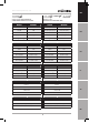
www.evolutionpowertools.com 210mm (8-1/4”) TCT MULTIPURPOSE SLIDING MITRE SAWS MACHINE SPECIFICATIONS METRIC IMPERIAL Motor UK (230V ~ 50/60 Hz) 1500W 7A Motor UK (110V ~ 50/60 Hz) 1500W 14A Motor USA (120V ~ 60 Hz) 1500W No Load Speed 3750min Weight 13A 3750rpm -1 N: 13kg / G: 14.
www.evolutionpowertools.com EN STEALTH 210mm (8-1/4”) TCT MULTIPURPOSE SLIDING MITRE SAW WITH 300mm SLIDE 255 255 255mm (10”) TCT MULTIPURPOSE SLIDING MITRE SAWS METRIC IMPERIAL METRIC IMPERIAL 1500W 7A 2000W (Soft Start) 9A (Soft Start) 1500W 14A 1600W (Soft Start) 15A (Soft Start) 1500W 13A 1800W (Soft Start) 15A (Soft Start) 3000min-1 3000rpm 2500min-1 2500rpm N: 13kg / G: 17kg N: 23lb / G:38 lb N: 19.
www.evolutionpowertools.com (1.3) IMPORTANT Please read these operating and safety instructions carefully and completely. For your own safety, if you are uncertain about any aspect of using this equipment please access the relevant Technical Helpline, the number of which can be found on the Evolution Power Tools website. We operate several Helplines throughout our worldwide organization, but Technical help is also available from your supplier. WEB www.evolutionpowertools.
www.evolutionpowertools.com EN (1.7) VIBRATION WARNING: When using this machine the operator can be exposed to high levels of vibration transmitted to the hand and arm. It is possible that the operator could develop “Vibration white finger disease” (Raynaud syndrome). This condition can reduce the sensitivity of the hand to temperature as well as producing general numbness. Prolonged or regular users of mitre saws should monitor the condition of their hands and fingers closely.
www.evolutionpowertools.com INTENDED USE OF THIS POWER TOOL (1.14) WARNING: This product is a Multipurpose Sliding Mitre Saw and has been designed to be used with special Evolution Multipurpose blades. Only use blades designed for use in this machine and/or those recommended specifically by Evolution Power Tools Ltd. This machine is fitted with the correct moulded plug and mains lead for the designated market.
www.evolutionpowertools.com EN SAVE ALL WARNINGS & INSTRUCTIONS FOR FUTURE REFERENCE The term “power tool” in the warnings refers to your mains-operated (corded) power tool or battery-operated (cordless) power tool. (2.2) 1. General Power Tool Safety Warnings [Work area safety] a. Keep work area clean and well lit. Cluttered or dark areas invite accidents. b. Do not operate power tools in explosive atmospheres, such as in the presence of flammable liquids, gasses or dust.
www.evolutionpowertools.com (2.5) 4) General Power Tool Safety Warnings [Power tool use and care]. a) Do not force the power tool. Use the correct power tool for your application. The correct power tool will do the job better and safer at a rate for which it was designed. b) Do not use the power tool if the switch does not turn it on or off. Any power tool that cannot be controlled with the switch is dangerous and must be repaired.
www.evolutionpowertools.com EN (3.5) MITRE SAW SPECIFIC SAFETY The following specific safety instructions for Mitre Saws are based on the requirements of EN61029-2-9:2009. BLADE SAFETY WARNING: Rotating Saw Blades are extremely dangerous and can cause serious injury and amputation. Always keep fingers and hands at least 150mm (6”) away from the blade at all times.
www.evolutionpowertools.com (3.7) (3.8) Always ensure that you have selected the correct saw blade for the material being cut. Do not use this mitre saw to cut materials other than those specified in this Instruction Manual. Wherever practicable always secure the work piece to the saw table using the work clamp where provided.
www.evolutionpowertools.com EN • To reduce the risk of back injury, hold the tool close to your body when lifting. Bending your knees so you can lift with your legs, not your back. Lift by using the handheld areas at each side of the machines base. • Never carry the Mitre Saw by the power cord. Carrying the Mitre Saw by the power cord could cause damage to the insulation or the wire connections resulting in electric shock or fire.
www.evolutionpowertools.com OVERALL VIEW OF MITRE SAW 20 4 21 1 22 2 10 3 8 9 7 11 16 6 18 5 17 13 15 12 19 14 12. MITRE HANDLE 13. MITRE ANGLE SCALE 14. POSITIVE STOP LOCKING LEVER 15. WORKPIECE SUPPORT (Optional Accessory) 16. REPEAT END STOP (Optional Accessory) 17. FENCE 18. HOLD DOWN CLAMP 19. MOUNTING HOLE (x 4) 20. ARBOR LOCK BUTTON 21. HEAD LATCHING PIN 22. DEPTH GAUGE 1. ON/OFF TRIGGER SWITCH 2. LOCK-OFF BUTTON 3. CUTTING HANDLE 4. DUST BAG (Optional Accessory) 5. ROTARY TABLE 6.
www.evolutionpowertools.com EN (7.1) ASSEMBLY AND PREPARATION 1 WARNING: Always disconnect the saw from the power source before making any adjustments. Note: It is recommended that all instructions are always read before operating. (7.2) Permanently mounting the mitre saw To reduce the risk of injury from unexpected saw movement, place the saw in the desired location either on a workbench or other suitable machine stand.
www.evolutionpowertools.com This arm will provide extra stability to prevent the machine from toppling in the event of sudden release of the Cutting Head. (7.4) Hold down clamp (Fig. 4) Two sockets (one either side) are incorporated into the rear of the machines fence. These sockets are for positioning the Hold Down Clamp. Fig. 4 Fig. 5 • Fit the clamp to the retaining socket that best suits the cutting application, ensuring that it is fully pushed down.
www.evolutionpowertools.com EN LASER ADJUSTMENT FOR EUROPEAN PLUG MODELS WARNING: At no time during this procedure should the motor be started. To check laser alignment: • Place a piece of cardboard, or similar, onto the rotary table of the machine. • With the carriage slide in the rearmost position, lower the Cutting Head so that a blade tooth makes a mark in the cardboard. • Allow the Cutting Head to rise, and then repeat the above with the carriage slide in an approximate mid- way position.
www.evolutionpowertools.com LASER ADJUSTMENT FOR NORTH AMERICAN PLUG MODELS WARNING: At no time during this procedure should the motor be started. The Laser Module is held in a ‘mounting block’, The ‘mounting block, itself is located within the machine on two (2) sprung loaded socket headed screws. Fig. 8a + 8b By loosening the cross headed screw (Fig. 8a) slightly, the Laser Module can be rotated slightly within the “mounting block’.
www.evolutionpowertools.com EN Note: The above adjustments & alignments should be checked on a regular basis to ensure laser accuracy. Note: The following WARNING labels may be found on this machine: LASER RADIATION DO NOT STARE INTO THE BEAM CLASS 2 LASER PRODUCT DE LASER SAFETY The Laser guide line used in this product uses a class 2 Laser with a maximum power output of 1mW at a wave length of between 635 and 670nm.
www.evolutionpowertools.com Fig. 9 To use the laser guide for an unknown angle: • Mark the position of the cut to be made on the workpiece using a pencil etc. • Place the workpiece on the rotary table and against the fence. • Adjust the mitre saw to give the approximate angle of cut. Do not tighten the mitre lock handle at this stage. • Slowly slide the workpiece backwards and forwards along the fence, whilst at the same time slowly adjusting the angle of the rotary table.
www.evolutionpowertools.com EN • When cutting is complete re-adjust the depth stop so that the Cutting Head can be locked in the down position by the head latching pin. Note: In many circumstances the depth stop can be left at the selected setting if desired. When the depth stop ‘stop plate’ is returned to the ‘normal’ position the depth stop screw will pass by the ‘stop plate’ and through a channel in the machines castings. DE (7.
www.evolutionpowertools.com (8.4) (8.3) BODY AND HAND POSITIONING ADJUSTMENT OF PRECISION ANGLES Several checks/adjustments are possible on this machine. The operator will require a 900 450/450 Set Square (not supplied) to carry out these checks and adjustments. WARNING: Checks/adjustments must only be conducted with the machine disconnected from the power supply. No-Hands Zone (Fig. 11) • Never place your hands within the ‘no hands zone’ (at least 150mm away from the blade).
www.evolutionpowertools.com EN BEVEL ANGLES (00 AND 450) 00 Bevel Stop Adjustment • Ensure that the Cutting Head is in the locked down position with the latching pin fully engaged in its socket. (see Fig.19) • Ensure that the Cutting Head is upright, against its stop and the bevel pointer is indicating 00 on the scale. (Fig. 12) • Place the Set Square on the table with one short edge against the table and the other short edge against the blade (avoiding the TCT tips). (Fig.
www.evolutionpowertools.com Fig. 16 450 Bevel Stop Adjustment • Loosen the Bevel Lock Handle and tilt the Cutting Head completely to the left until it rests against the 450 stop. • Use a Set Square to see if the blade is at 450 to the table (avoiding the TCT tips). • If the saw blade is not in exact alignment adjustment is necessary. • Return the Cutting Head to its upright position. • Loosen the locknut on the 450 Bevel Adjustment Screw.
www.evolutionpowertools.com EN • Ensure that the Cutting Head is in the locked down position with the latching pin fully engaged in its socket • Place a Set Square on the table with one short edge against the Fence and the other short edge against the Blade (avoiding the TCT tips). (Fig. 19) • If adjustment is necessary, loosen the four Fence adjustment screws using a Hex Key • Re-position the Fence in its elongated slots until alignment is achieved. • Securely tighten the socket head Hex screws. DE Fig.
www.evolutionpowertools.com Step 1 & 2 UNLATCHING AND RAISING THE CUTTING HEAD (Fig. 21) WARNING: To avoid serious injury, NEVER perform the unlocking or locking procedure unless the saw is OFF and the blade stopped. Step 3 To Release the Cutting Head from the Locked Down position: • Gently press down on the Cutting Handle. • Pull out the head latching pin and allow the Cutting Head to rise to its upper position.
www.evolutionpowertools.com EN • Slide the Cutting Head to the rear as far as it will go. • Tighten the slide lock screw. (Fig. 24) • Place the workpiece on the table and against the fence and secure with clamp(s) as appropriate. • Grasp the saw handle. • Turn the motor on and allow the saw blade to reach full speed. • Remember to press the lock-off button first before the On/Off switch. (Fig. 25) • Lower the Cutting Handle downwards and cut through the workpiece.
www.evolutionpowertools.com • Always push the Cutting Head to the full rear position during each cut. (Fig. 28) • When the cut has been completed, release the trigger switch and allow the blade to come to stop. • Allow the Cutting Head to rise to its upper position, with the lower blade guard completely covering the blade teeth, and the Cutting Head locked in the upper position, before releasing the Cutting Handle. WARNING: Never pull the Cutting Head and spinning blade Fig.
www.evolutionpowertools.com EN BEVEL CUTTING - TILTING THE CUTTING HEAD A bevel cut (Fig. 32) is made with the rotary table set at 00 mitre. Note: It may be necessary to adjust the upper section of the Fence to provide clearance for the moving Cutting Head. The Cutting Head can be tilted from the normal 00 (perpendicular position) to a maximum angle of 450 from the perpendicular to the left hand side only. Bevel cutting is possible with or without the sliding carriage system being deployed. DE Fig.
www.evolutionpowertools.com Ensure that the Crown Moulding is correctly positioned on the rotary table before making the cut. When cutting operations are completed, return the Cutting Head to the vertical position and return the Crown Moulding Pin to its outer (disengaged) positioned. (8.7) COMPOUND CUTTING (Fig. 36) Fig. 36 A compound cut is a combination of a mitre and bevel cut employed simultaneously.
www.evolutionpowertools.com EN INSTALLING or REMOVING a BLADE WARNING: Only carry out this operation with the machine disconnected from the mains supply. WARNING: Only use genuine Evolution blades or those blades specifically recommended by Evolution Power Tools and which are designed for this machine. Ensure that the maximum speed of the blade is higher than the speed of the motor.
www.evolutionpowertools.com 25.4mm (1”) ARBOR (ELEVATED) SILVER DUAL-SIDED INNER-FLANGE (NORTH AMERICAN MODELS ONLY) North American models only are supplied with a silver dual-sided inner-flange which enables you to safely fit Evolution multipurpose blades with a 25.4mm (1”) arbor and by ‘reversing’ this dual-sided inner-flange, you can also safely fit saw blades with a 16mm (5/8”) arbor as available in the North American market. Note: Evolution Multipurpose blades save time and money.
www.evolutionpowertools.com EN WARNING: Only carry out this operation with the machine disconnected from the mains supply. WARNING: You must ensure the silver dual-sided inner flange side marked 16mm (5/8”) visible to you is correct for the blade arbor you are fitting. The silver dual-sided inner flange is marked with the relevant arbor size each side. Do not fit a 25.4mm (1”) arbor blade to the 16mm (5/8”) marked silver dual-sided inner-flange side.
www.evolutionpowertools.com (8.12) USE OF OPTIONAL EVOLUTION ACCESSORIES Not supplied as original equipment. All accessories can be purchased from Evolution Power Tools. See ‘Additional Accessories’ section. (8.13) DUST BAG Fig. 41 A Dust Bag can be fitted to the extraction port at the rear of the machine. The Dust Bag is for use when cutting wooden materials only. • Slide the Dust Bag over the dust extraction port, ensuring that the spring clip grips the port holding the Dust Bag securely in place.
www.evolutionpowertools.com EN • Right Hand side. Loosen the support retaining screw located in the top front of the machines base. • Insert the workpiece supports bars into the retaining holes in the base. Push fully home to ensure positive location. Note: Approximately 75mm of the Workpiece Support Bar should slide into the base to provide positive location. DE • Tighten the retaining screw. • Repeat the above for the Left Hand side.
www.evolutionpowertools.com FINAL SAFETY CHECKS Condition Slides Inserted through the Bevel Neck and connected to the Cutting Head. Locating lugs successfully deployed Positive Stop Locking Lever Installed onto Locking Mechanism Mitre Locking Handle Installed onto Locking Screw Power Cable Routed correctly and fastened to back slide bracket. 50 – 60mm max deflection at the midpoint Blade Blade installed with rotation arrows matching.
www.evolutionpowertools.com EN MAINTENANCE Note: Any maintenance must be carried out with the machine switched off and disconnected from the mains/battery power supply. Check that all safety features and guards are operating correctly on a regular basis. Only use this machine if all guards/safety features are fully operational. All motor bearings in this machine are lubricated for life. No further lubrication is required. Use a clean, slightly damp cloth to clean the plastic parts of the machine.
www.evolutionpowertools.com EC DECLARATION OF CONFORMITY The manufacturer of the product covered by this Declaration is: Evolution Power Tools, Venture One, Longacre Close, Holbrook Industrial Estate, Sheffield, S20 3FR. The manufacturer hereby declares that the machine as detailed in this declaration fulfils all the relevant provisions of the Machinery Directive and other appropriate directives as detailed below.
www.evolutionpowertools.
UK Evolution Power Tools Ltd Venture One Longacre Close Holbrook Industrial Estate Sheffield S20 3FR US Evolution Power Tools LLC 8363 Research Drive Davenport Iowa 52806 +44 (0)114 251 1022 866-EVO-TOOL エボリューション パワーツール株式会社 〒544-0031 大阪府大阪市生野区 鶴橋5丁目21-19 JP EU Evolution Power Tools Ltd 61 Avenue Lafontaine 33560 Carbon-Blanc Bordeaux 0120-051-415 + 33 (0)5 57 30 61 89 Discover Evolution Power Tools Visit: www.evolutionpowertools.