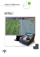
User’s Manual Version 1.
Epsio Version 1.60 – User’s Manual EVS Broadcast Equipment – July 2010 Issue 1.60.C C OPYRIGHT EVS Broadcast Equipment – Copyright © 2010. All rights reserved. D ISCLAIMER The information in this manual is furnished for inform ational use only and subject to change without notice.
Issue 1.60.C II Epsio Version 1.
Epsio Version 1.60 – User’s Manual EVS Broadcast Equipment – July 2010 Issue 1.60.C Table of Contents TABLE OF CONTENTS ................................................................................................... III WHAT’S NEW.................................................................................................................... 1 1. OVERVIEW ............................................................................................................... 2 1.1 PRODUCT DESCRIPTION .....
Issue 1.60.C Epsio Version 1.60 – User’s Manual EVS Broadcast Equipment - July 2010 2.5 ADDING AND CUSTOMIZING THE GRAPHIC SUITE ..............................................................39 2.5.1 Graphic Suite Definition and Components ............................................................................39 2.5.2 Tools Tab ..............................................................................................................................40 2.5.3 How to Create a Graphic Suite .........
Epsio Version 1.60 – User’s Manual Issue 1.60.C EVS Broadcast Equipment – July 2010 What’s New The following table describes the sections updated to reflect the new and modified features on Epsio 1.60 (compared to Epsio 1.58). has been added on left margin to highlight In the user manual, the icon information on new and updated features. Click the section number (or the description) in the table to jump directly to the corresponding section. Section Description Section 1.
Issue 1.60.C Epsio Version 1.60 – User’s Manual EVS Broadcast Equipment - July 2010 1. Overview 1.1 PRODUCT DESCRIPTION Epsio is a graphics solution integrated into the MulticamLSM that allows the operators to control graphic animations, such as offside line, graphic overlays, arrows or circles, using the LSM Remote Panel. It can be used with the EVS XT family servers and works with Multicam, from version 10.2.30 onwards.
Epsio Version 1.60 – User’s Manual EVS Broadcast Equipment – July 2010 Issue 1.60.
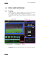
Issue 1.60.C Epsio Version 1.60 – User’s Manual EVS Broadcast Equipment - July 2010 1.3 EPSIO USER INTERFACE 1.3.1 OVERVIEW You will access Epsio by clicking the Epsio icon on the desktop, or via the Start menu in Program Files > EVS Broadcast Equipment > Epsio > Epsio .
Epsio Version 1.60 – User’s Manual Issue 1.60.C EVS Broadcast Equipment – July 2010 Note When the offside line mode is activated on the LSM Remote Panel, you cannot use the mouse outside the operating monitor in Epsio. To be able to move the mouse in the whole Epsio window, do one of the following: • In Epsio, press on the keyboard. • Press RECORD on the LSM Remote Panel to go out of the offside line mode. 1.3.
Issue 1.60.C 1.3.4 Epsio Version 1.60 – User’s Manual EVS Broadcast Equipment - July 2010 CAMERA ANGLE LIST The Camera Angle list shows a thum bnail for each camera angle that has been defined and/or calibrated. You can select a camera angle by clicking the thumbnail. This Camera Angle list is particularly useful in the Calibration phase. When the camera angle has only been created, but not calibrated yet, the thumbnail shows a grey background and the virtual playfield.
Epsio Version 1.60 – User’s Manual Issue 1.60.C EVS Broadcast Equipment – July 2010 2. Configuration 2.1 OVERVIEW The configuration in order to use Epsio with an EVS server has to be performed in the Epsio application or on the EVS server side (via the EVS menu and the LSM Remote Panel), depending on the configuration step. 2.1.1 CONNECTION STEPS Before you can actually configure Epsio, you first need to set up Epsio and the EVS server to communicate with each other: 2.1.
Issue 1.60.C 2.1.3 Epsio Version 1.60 – User’s Manual EVS Broadcast Equipment - July 2010 SAVING AND MANAGING THE CONFIGURATION The commands available in the the File menu allow you to save and manage the configuration you will perform. The configuration, which includes the camera calibration and the chroma key definition, is saved in a configuration file that is made up of two .xml files: • A file containing the playfield distances and all camera angle definitions. This file is ‘name’.
Epsio Version 1.60 – User’s Manual Issue 1.60.C EVS Broadcast Equipment – July 2010 2.2 CONNECTING EPSIO AND EVS SERVER 2.2.1 STARTING THE EVS SERVER APPLICATION When using Epsio with an EVS server, you need to run a server application: • with at least 2 recorder channels and 2 player channels • in a Multicam LSM base configuration. For more information on starting an EVS application, refer to the EVS Menu section in the Technical Reference Software manual. 2.2.
Issue 1.60.C 2.2.3 Epsio Version 1.60 – User’s Manual EVS Broadcast Equipment - July 2010 ACTIVATING THE CONNECTION BETWEEN EPSIO AND THE EVS SERVER To activate the offside line mode and the external offside line mode, proceed as follows: 1. From the Main menu, select Setup by pressing SHIFT + D to enter the Setup menu. 2. Press the F9 key to go to the Special Effects settings, and then F0 to open page 9.2. 3. Press F2 to access the Offside Line setting and rotate the jog dial to set it to ‘ON’.
Epsio Version 1.60 – User’s Manual EVS Broadcast Equipment – July 2010 Issue 1.60.C 2. In the Setup group box, select the Video Format you are working with and the type of Genlock system you are using. 3. Click the Open button. Epsio checks the format you have specified is compatible with the format used by the EVS server. Epsio automatically grabs and displays an image of the video signals delivered to the IN connectors and sent from the OUT connectors. 4.
Issue 1.60.C Epsio Version 1.60 – User’s Manual EVS Broadcast Equipment - July 2010 2.3 CALIBRATING THE CAMERAS 2.3.1 INTRODUCTION In Epsio, calibrating the cameras consists of positioning a virtual playfield in a 3D environment to match the position of the actual playfield used for a given event. You calibrate the cameras in the Calibration tab in Epsio.
Epsio Version 1.60 – User’s Manual Issue 1.60.C EVS Broadcast Equipment – July 2010 Area Description General This area allows you to modify the default playfield size (105 meters by 68 meters), as well as to display and/or modify the grid of the virtual playfield. See also ‘General Area’, on page 17.
Issue 1.60.C Epsio Version 1.60 – User’s Manual EVS Broadcast Equipment - July 2010 C AMERA C REATION A REA This area allows you to add cameras, and assign them to a recorder channel on an EVS server. Field Description Buttons that allow the user to define a new camera in the system. Several preset cameras are available: • The Add button below the 16 Left label allows adding a 16-meter left-angle camera. It creates two cameras angles (goal and center).
Epsio Version 1.60 – User’s Manual Issue 1.60.C EVS Broadcast Equipment – July 2010 C URRENT C AMERA A REA This area allows you to perform several actions on the current camera. The current camera is the one selected in the Camera Angle list. This is displayed in a blue frame in the Camera Angle list. Field Description Displays the name of the camera selected in the Camera Angle list below the operating monitor. The camera name can only be modified using the Rename button.
Issue 1.60.C Epsio Version 1.60 – User’s Manual EVS Broadcast Equipment - July 2010 Field Description Check box that allows the system to detect the central circle when the user creates an offside line anim ation. When you calibrate a center camera angle, tick this check box. For the automatic detection to work properly, the image should clearly display the central circle. Snap Button used to grab a new image of the playfield on which the calibration of the camera will be based.
Epsio Version 1.60 – User’s Manual Issue 1.60.C EVS Broadcast Equipment – July 2010 G ENERAL A REA This area allows you to modify the size of the virtual playfield, and whether/how grids will be displayed on the virtual playfield. Field Description Length Slider to modify the default playfield length (105 meters). Width Slider to modify the default playfield length (68 meters).
Issue 1.60.C 2.3.3 Epsio Version 1.60 – User’s Manual EVS Broadcast Equipment - July 2010 HOW TO CALIBRATE THE CAMERAS Note The calibration steps explained in the sections below illustrate the calibration of the two 16-meter cameras used with the offside line tool. However, the same procedure applies to the calibration of the free camera for the live tools. Once Epsio is open, you calibrate the various cameras in the CALIB tab, in the following way: 1.
Epsio Version 1.60 – User’s Manual Issue 1.60.C EVS Broadcast Equipment – July 2010 c. Click in the Current area in Epsio. For more information, refer to the section 2.3.4 ‘Good Snapshots of the Playfield’, on page 20. 3.
Issue 1.60.C Epsio Version 1.60 – User’s Manual EVS Broadcast Equipment - July 2010 6. Load the test snapshots, and perform the necessary adjustments, by repositioning only the anchor points initially matched in step 3. For more information on the calibration tests, see the section 2.3.6 ‘Testing your Calibration’, on page 24. 7. On a shot that includes the 16-m eter line, and part of the central circle, add virtual points for offside shots where playfield lines would not be visible.
Epsio Version 1.60 – User’s Manual EVS Broadcast Equipment – July 2010 Issue 1.60.C S NAPSHOTS FOR THE G OAL A REA C ALIBRATION The snapshot for the goal area of the left or right 16-meter camera should show: • the whole left or right penalty area (respectively) with 16-meter line, including the goal area with the 6-meter line • the goal line along the goal area, • part of each touchline on both sides of the playfield.
Issue 1.60.C Epsio Version 1.60 – User’s Manual EVS Broadcast Equipment - July 2010 S NAPSHOTS FOR THE C ENTRAL C IRCLE C ALIBRATION The snapshot for the central circle of the left or right 16-meter camera should show: • the whole central circle (not the full central line), • the 16-meter line of the left or right penalty area (respectively), and the penalty arc. • part of each touchline on both sides of the playfield.
Epsio Version 1.60 – User’s Manual EVS Broadcast Equipment – July 2010 2.3.5 Issue 1.60.
Issue 1.60.C Epsio Version 1.60 – User’s Manual EVS Broadcast Equipment - July 2010 A DDITIONAL T IPS Here are the following tips to help you in this step: • Once you have selected a virtual point, you can adjust its position using the arrows on your keyboard. • The four anchor points you use to calibrate a camera angle should not be aligned. • Always match the points to the same edge of the lines. • You can use more than 4 points to perform the calibration.
Epsio Version 1.60 – User’s Manual EVS Broadcast Equipment – July 2010 Issue 1.60.C 2 n d test Move the camera to the bottom corner arch without changing the zoom. Check that the 16-meter line and 6-meter line are correctly matched. 3 r d test Move the camera back to the goal area, keeping the 6-meter and 16-meter lines. All lines must match. If the tests are not satisfactory, refine the calibration by matching several calibration points again.
Issue 1.60.C Epsio Version 1.60 – User’s Manual EVS Broadcast Equipment - July 2010 T ESTING THE C ENTRAL CIRCLE All lines must be correctly matched on the calibration shot. Besides this, you should test three additional test shots: 1 s t test Using the same view as your calibration shot. Check that the central circle is correctly matched, and that the borders of the halfway line are correctly matched. If necessary, reposition the faulty anchor points.
Epsio Version 1.60 – User’s Manual EVS Broadcast Equipment – July 2010 Issue 1.60.C 3 r d test Move and zoom the camera to view the 6-meter line, and part of the half-way line. Use this test shot to add your additional virtual points. 2.3.7 ADDING VIRTUAL POINTS During the calibration, it is recommended to create additional virtual points outside the playfield, using the stadium geom etry (first step of the terracing, static banners around the field, and so on).
Issue 1.60.C Epsio Version 1.60 – User’s Manual EVS Broadcast Equipment - July 2010 2.4 CONFIGURING THE CHROMA KEY 2.4.1 GENERAL INFORMATION C ONCEPT OF C HROMA K EY The chroma keying is a technique for compositing two images or fram es together in which a color (or a range of colors) from the main image (video signal) is removed (or made transparent), revealing another im age behind it. The key is the image that punctures through the image of the video signal.
Epsio Version 1.60 – User’s Manual Issue 1.60.C EVS Broadcast Equipment – July 2010 I MPACT OF L IGHT C ONDITIONS As the chroma key depends on the light, it is recommended to configure the chroma key 30 minutes before the match to get the closest to the light conditions that will prevail during the match. For a match during the day, you should perform two chroma key configurations: one for light, one for dark, to allow you to cope with shadows on the playfield.
Issue 1.60.C Epsio Version 1.
Epsio Version 1.60 – User’s Manual EVS Broadcast Equipment – July 2010 2.4.3 Issue 1.60.C CHROMA KEY PARAMETERS You can create and manage up to four chroma key definitions from the LSM Remote Panel, or in Epsio, using the chroma key profiles. The various chroma key parameters allow you to define or refine a chroma key profile. The representation of the chroma key definition in a color space will help you visualize the range of colors taken into account in the chroma key definition.
Issue 1.60.C Epsio Version 1.60 – User’s Manual EVS Broadcast Equipment - July 2010 D EFINITION OF THE C HROMA K EY P ARAMETERS The chroma key parameters are explained in the table below: Parameter Description RGB Hue Value Definition X Moves left and right the color range in the color space. Y Moves up and down the color range in the color space. Tolerance Definition Width (W) Widens or narrows the color range on the X axis in the space.
Epsio Version 1.60 – User’s Manual Issue 1.60.C EVS Broadcast Equipment – July 2010 2.4.4 CHROMA KEY EDIT SCREEN ON THE REMOTE PANEL I NTRODUCTION You define and manage the chroma key definition from the Chroma Key edit screen. When you are in this screen, the Edit mode is directly active.
Issue 1.60.C 2.4.5 Epsio Version 1.60 – User’s Manual EVS Broadcast Equipment - July 2010 Field area or button Description Save As (SHIFT+C) Press this key, followed by a key corresponding to a chroma key profile to save the currently loaded chroma key definition under the selected chroma key profile. Quit (SHIFT+D) Press this key to leave the chroma key edit screen. Profile 1 (A) to Profile 4 (D) Four profiles under which the chroma key definitions can be saved.
Epsio Version 1.60 – User’s Manual Issue 1.60.C EVS Broadcast Equipment – July 2010 F IELDS AND C OMMANDS IN THE CHROMA T AB The following table describes the field boxes and buttons on the tab: User Interface Element Description Profiles area EVS Profiles list Lists the chroma key profiles available in the Chroma Key edit screen of the LSM Remote Panel: • Clicking the profile will load a preview of the chroma key on the preview area.
Issue 1.60.C 2.4.6 Epsio Version 1.60 – User’s Manual EVS Broadcast Equipment - July 2010 METHODS AND RECOMMENDATIONS FOR THE CHROMA KEY DEFINITION M ETHODS There are several ways to configure your chroma key. This section will explain the two main methods: • Defining a chroma key based on an autom atically generated chroma key. • Defining a chroma key based on an area selected on a playfield. S TEPS In both methods, you need to go through the following steps: 1. Accessing the Chroma Key edit screen.
Epsio Version 1.60 – User’s Manual Issue 1.60.C EVS Broadcast Equipment – July 2010 2.4.7 HOW TO CONFIGURE A CHROMA KEY BASED ON AN AUTOMATIC CHROMA KEY The automatic chroma key is based the colors located within the virtual playfield. For this reason, the virtual playfield must be correctly matched to the real playfield on the snapshot you will use for the automatic chroma key. To configure a chroma key based on an automatic chroma key, proceed as follows: 1.
Issue 1.60.C 2.4.8 Epsio Version 1.60 – User’s Manual EVS Broadcast Equipment - July 2010 HOW TO CONFIGURE A CHROMA KEY BASED ON AN AREA SELECTED ON THE PLAYFIELD To configure a chroma key based on an area selected on the Playfield, proceed as follows: 1. In the main operational menu, jog to an im age of the real playfield that you will use for the chroma key configuration. 2. Press SHIFT+D to enter the Epsio menu. 3. Press SHIFT+B to enter the Chroma Key edit screen.
Epsio Version 1.60 – User’s Manual EVS Broadcast Equipment – July 2010 2.5 ADDING AND CUSTOMIZING THE GRAPHIC SUITE 2.5.1 GRAPHIC SUITE DEFINITION AND COMPONENTS Issue 1.60.C The graphic suite includes the graphic packs for the various tools you can use in Epsio (offside, arrow, circle, graphics). The graphic pack contains the definition of the components of a given Epsio graphic tool, in other words this is the graphic chart of the tool.
Issue 1.60.C 2.5.2 Epsio Version 1.
Epsio Version 1.60 – User’s Manual Issue 1.60.C EVS Broadcast Equipment – July 2010 A CTIONS A REA The following table describes the user interface elements in the Actions area: Button Description New Action Not applicable. The fields in this area aim at creating the offside line animations. As Epsio is used in combination with the LSM Remote Panel, the offside line animations are created on the Remote Panel. G RAPHICS A REA You will define your graphic suite in the Graphics area.
Issue 1.60.C Epsio Version 1.60 – User’s Manual EVS Broadcast Equipment - July 2010 Field/Button Description Button to save the currently open graphic suite. Button to save the currently open graphic suite under a new name. Name of the loaded suite P ACK A REA The Pack area allows you to select the tool and the graphic pack that you want to edit. Field/Button Description Drop-down field to select the graphic tool for which you want to define a graphic pack.
Epsio Version 1.60 – User’s Manual Issue 1.60.C EVS Broadcast Equipment – July 2010 General Parameters The general parameters associated to the loaded target are displayed on the left. These parameters are described in the table below. Field/Button Description Specifies the color of the selected component. Click the color frame to open the color palette, and select the requested color. Slider that allows defining the transparency of the Alpha layer of the selected component.
Issue 1.60.C 2.5.3 Epsio Version 1.60 – User’s Manual EVS Broadcast Equipment - July 2010 HOW TO CREATE A GRAPHIC SUITE This procedure explains how to create and customize a graphic suite. If you want to include default graphic packs in your graphic suite without customizing them, skip the step 7. To create a graphic suite, proceed as follows: 1.
Epsio Version 1.60 – User’s Manual EVS Broadcast Equipment – July 2010 Issue 1.60.C page 42, if necessary. c. Repeat steps a and b for all the targets you want to customize. d. Click the Save button regularly to save your changes. 7. Repeat the steps 4 to 6 for each tool available in Epsio. 8.
Issue 1.60.C Epsio Version 1.60 – User’s Manual EVS Broadcast Equipment - July 2010 R EPLAY S ETTINGS The following table explains briefly the replay settings: Setting Description Pause Duration Duration of the pause before displaying the animation. The pause duration can be between 0 and 300 frames. It is recommended to have a minimum value of 3 frames. Fade In Duration Duration of the fade effect at the beginning of the animation. The fade in duration can be between 0 and 300 frames.
Epsio Version 1.60 – User’s Manual Issue 1.60.C EVS Broadcast Equipment – July 2010 3. Creating Graphic Animations 3.1 GENERAL INFORMATION 3.1.
Issue 1.60.C Epsio Version 1.60 – User’s Manual EVS Broadcast Equipment - July 2010 E PSIO M AIN M ENU Graph ChromaK OSD <-- Calib Calib --> Detect The Epsio main menu contains the following commands: Command Description Graph Allows the user to display or hide the Epsio animation that has been created. The Graph command is active when you enter the Epsio menu. ChromaK Allows the user to enter the Chroma Key menu, in which you can configure the chroma key definition. Refer to the section 2.4.
Epsio Version 1.60 – User’s Manual Issue 1.60.C EVS Broadcast Equipment – July 2010 3.2 CREATING AN OFFSIDE ANIMATION 3.2.1 REMOTE MENU WITH OFFSIDE FEATURE ACTIVE If you want to create an offside line, you need to do the follow ing before you enter the Epsio menu: • Have the offside line mode activated as default mode • Position on the fram e where you want to create an offside line animation.
Issue 1.60.C Epsio Version 1.60 – User’s Manual EVS Broadcast Equipment - July 2010 P ROCEDURE To validate the playfield limits, proceed as follows: 1. When you have entered the offside line mode, right-click one of the points on the virtual field. This can be a virtual point you have added during the calibration. 2. Drag the virtual field to match the real playfield. 3. Release the mouse. 4. Jog with the wheel to adjust the zoom.
Epsio Version 1.60 – User’s Manual Issue 1.60.C EVS Broadcast Equipment – July 2010 9. Press RECORD to go out of the Epsio menu. If the operator keeps the Graph command active, the graphic will be played when the clip will go on air. If the director invalidates the offside line on his preview, the operator can press A again to deactivate the Graph command. When the clip will go on air, the offside sequence will be played out ‘clean’, without the offside line animation. 3.3 CREATING A LIVE ANIMATION 3.
Issue 1.60.C Epsio Version 1.60 – User’s Manual EVS Broadcast Equipment - July 2010 If the director invalidates the offside line on his preview, the operator can press A again to deactivate the Graph command. When the clip will go on air, the offside sequence will be played out ‘clean’, without the offside line animation. 3.3.
EVS Broadcast Equipment Liège Science Park 16, rue Bois St Jean B-4102 Ougrée Belgium Corporate Headquarters North & Latin America Headquarters Asia & Pacific Headquarters Other regional offices available on +32 4 361 7000 +1 973 575 7811 +852 2914 2501 www.evs.tv/contact To learn more about EVS go to www.evs.