
User Guide
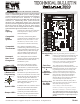


10
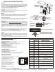
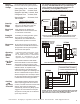
The UT3000 panel was designed to be easy to wire up and operate.
We have provided several typical field wiring diagrams to review.
Your actual field wiring may vary. In full communicating mode, 4
wires are all that is required from each thermostat and to the HVAC
system. The UT3000 will “Talk” to the HVAC system and “Talk” to
the thermostats in order to automatically setup and start operating
the HVAC system. In 24volt mode, you can program the UT3000 to
operate the type of HVAC system you are installing. Either way, the
UT3000 allows you to Plug & Play or Program & Play!
Four wires are all that is required to each
component. Plug & Play
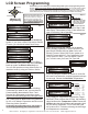
System Wiring
Communicating
Dual Fuel or Standard
Heat Pump
System
Standard
Heat Pump
with “O” Type
Reversing Valve
EWC Controls Inc. 385 Highway 33 Englishtown, NJ 07726 800-446-3110 FAX 732-635-8646 E-Mail- info@ewccontrols.com
Figure 3a
Figure 3b
Figure 3d
Typical heat pump system wiring with either
Electric or Fuel Backup heat. Applies to air
cooled or geothermal HVAC systems.
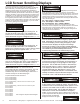
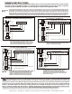
Program& Play
TYPICAL BOILER
control circuit
or
HYDRONIC
CIRCULATOR
control
terminal block
Existing
Boiler with
New A/C
You may have a new Communicating A/C unit but still
want to use your Old Boiler as the Heating system.
Simply connect the T&T circuit from your boiler
control panel to the Rh and W1/B terminals on the
UT3000 and your done. Plug & Play
Communicating
AIR HANDLER
OR
FURNACE
Communicating
OUTDOOR
HEAT PUMP
2
1
C
R
2
1
C
R
W2/E
W1/B
SYSTEMSYSTEM
RH
RC
O
Y
G
RC/RH
LINK
RC/RH
LINK
UT3000
C
2
1
C
R
S
Y
S
T
E
M
Air Handler
with Electric
Backup Heat
or
Fossil Fuel Furnace
HEAT PUMP
1 STAGE
X / W
O
Y
C
R
W2
W1
Y
G
R
C
W2/E
W1/B
SYSTEMSYSTEM
RH
RC
O
Y
G
RC/RH
LINK
RC/RH
LINK
UT3000
C
2
1
C
R
S
Y
S
T
E
M
O
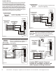
Four wires are all that is required to each
component. Plug & Play
Communicating
Fuel/Electric
System
Communicating
AIR HANDLER
Communicating
OUTDOOR
CONDENSING UNIT
2
1
C
R
2
1
C
R
W2/E
W1/B
SYSTEMSYSTEM
RH
RC
O
Y
G
RC/RH
LINK
RC/RH
LINK
UT3000
C
2
1
C
R
S
Y
S
T
E
M
T
T
T
T
To Radiant Floor Loop
Control Thermostat
White
Yellow
Green
Red
Figure 3c
Communicating
FURNACE
Communicating
OUTDOOR
CONDENSING
UNIT
2
1
C
R
2
1
C
R
W2/E
W1/B
SYSTEMSYSTEM
RH
RC
O
Y
G
RC/RH
LINK
RC/RH
LINK
UT3000
C
2
1
C
R
S
Y
S
T
E
M
White
Yellow
Green
Red
White
Yellow
Green
Red
Contact EWC Controls Technical
Support for assistance on these and
other Equipment Wiring Solutions.