
User Guide


Forward
Back
INSTALLATION INSTRUCTIONS
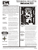
UT3000 Version 1.06 SPECIFICATIONS:
NUMBER OF ZONES: 2 or 3 Zones, Non-Expandable
COMPATIBLE EQUIPMENT:
Climate Talk™ based Communicating HVAC systems - Up to 4 Stages Heating and 2
Stages Cooling
Gas/Electric/Hydro – Up to 2 Stages Heating and 1Stage Cooling
Heat Pump Conventional or Dual Fuel – Up to 2 Stages Heating and 1 Stage Cooling
COMPATIBLE THERMOSTATS:
Climate Talk™ based Communicating HVAC Thermostat
Any single stage Heat/Cool Thermostat
Any 2 Stage Heat, 1 Stage cool Heat Pump Thermostat
COMPATIBLE DAMPERS:
EWC® Ultra-Zone® Models URD, ND, RSD and SID, Or
Any Competitor’s 24vac 3 Wire or 2 Wire damper
MAX. DAMPERS PER ZONE:
Up to 18 ND, URD, or SID Dampers Per Zone @ 26mA per damper. Total 54
Only 1 Spring Type Damper Per Zone @ 400mA per damper. Total 3
OVER-CURRENT PROTECTION:
2.5Amp main circuit board protection
500mA on each Damper Motor Terminal Block
140mA on each Communicating Thermostat and HVAC System Terminal Block
140mA on each Regular 24v Thermostat Terminal Block
UT3000 MAXIMUM CURRENT DRAW = .5 Amp
POWER REQUIREMENT = 24Vac 40Va 50/60 Hz
AMBIENT OPERATING CONDITIONS:
TEMPERATURE: -4° to 158°F (-20° to 70°C)
HUMIDITY: 0% - 95% Rh Non-Condensing
ANCILLARY IAQ DRY RELAY FUNCTIONS:
Operate a Humidifier or De-Humidifier
Control a Fresh Air or Combustion Air Damper
Operate & Interlock an ERV or HRV
ACCESSORIES:
Model SAS – Supply Air Sensor (Included)
Model OAS – Outdoor Air Sensor (Optional/Recommended)
Model CPLS – Coil Protection Lockout Switch (Optional/Recommended)
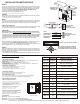
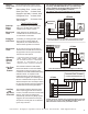
MOUNT:
Choose a suitable location to mount the UT3000 housing. Likely locations are the
Return Duct, a Nearby Wall or Convenient Studs where plywood can be installed
to support the housing. Avoid mounting the UT3000 on the Supply duct. Do not
mount the UT3000 directly to any Air-Handler, Furnace, Hot Water Coil or
Evaporator Cabinet to avoid damage to these devices.
Follow National and/or Local Mechanical Code.
POWER:
EWC always recommends to install a separate transformer to power the UT3000.
Follow NEC and/or Local Electrical Code.
WIRE:
Connect your thermostats and your dampers. Use the provided knock-outs as the
wire entry-way. Strip the jacket back to where the cable enters the housing. That
makes for less bulk and allows easy routing of the wires for a clean install.
4 Wire Comm Network:
Adhere to the Climate Talk™ Color Code. RED, GREEN, YELLOW, WHITE. Doing
so reduces the possibility of mis-wiring between devices on the Network.
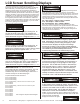
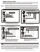
PROGRAM:
When connected to a Fully Communicating HVAC system, programming is
not required. The UT3000 will automatically configure the entire system and start
running as soon as thermostat demands are detected. Allow at least 1-2 minutes
for all Thermostats and the HVAC system to fully configure on the network.
The Default Supply air temperature Targets and off-set Limits will be used. Other
unique features can be selected and/or you can adjust the default settings
yourself.
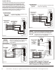
When connected to a Conventional 24v HVAC system, you simply scroll thru the
LCD menu and select the type of HVAC system you have and the type of
thermostats you want to use. The Default Supply air temperature Targets and off-
set Limits will be used, or you can adjust your own settings.
FINISH:
When the Installation is complete, run the system thru it’s paces and observe the
operation of the HVAC system in all possible modes of operation. Check the Zone
Dampers and the Bypass Damper for proper operation. Balance the System and
make adjustments as necessary.
If you need help, call the Technical Support Hotline for assistance 800-446-3110.
2
EWC Controls Inc. 385 Highway 33 Englishtown, NJ 07726 800-446-3110 FAX 732-446-5362 E-Mail- info@ewccontrols.com
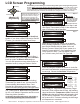
FEATURE
DEFAULT
RANGE TO SELECT
System Type
HP Type
T-Stat Type
Rev Valve
Fan Mode
Heat/Cool
NON
Dual Fuel
RV ‘O’
Hydro
OAS SP
15°
O.T. Offset
15°
10°
U.T. Offset
SAS HP TGT
SAS Gas TGT
SAS Cool TGT
110°
140°
55°
PURGE FAN
SAS RSP DLY
W2 Threshold
60s
85%
25%
Heat Pump or Heat/Cool
Dual Fuel or Non-Dual Fuel
Heat Pump or Heat/Cool
‘O’ Type RV or ‘B’ Type RV
GAS or HYDRO (Electric)
OFF or 7° to 42° F.
5° to 20° F.
5° to 12° F.
90° to 120° F.
120° to 170° F.
45° to 60° F.
10seconds - 180seconds
65% - 99% (Adj. in 5 point increments)
0% - 100% (Adj. in 25 point increments)
F
ield
S
up
p
li
ed
*
D
ed
icated *
Listed
Tran
s
fo
rm
e
r
24v
a
c
40va
Min / 60v
a M
a
x
To Zone
Control
Panel
To
Protected
Line
Voltage
R
C
10.00”
1.70”
9.875”
CONTROLS INC.
E
W
NOMINAL DIMENSIONS
10” X 10” X 1.75”
CO
NTR
OLS
IN
C.
E
W
OK
WHITE
YELLOW
GREEN
RED
2
1
C
R
FROM
COMMUNICATING
HVAC SYSTEM
or
COMMUNICATING
THERMOSTAT
Typical Up-flow
Installation with
DX Cooling
Avoid
mounting
in these
locations
Upon Power Up, Press and Hold the
Back & Forward buttons to Load the
Factory Default Values, then Release.
Default Loaded
Power Supply
If desired, you can reset the UT3000.
Install a Separate
Transformer
to Power the UT3000
Stick with the
Color Code & Protect
the Wires
Heat/Cool